HAL Id: ineris-00971823
https://hal-ineris.archives-ouvertes.fr/ineris-00971823
Submitted on 3 Apr 2014HAL is a multi-disciplinary open access archive for the deposit and dissemination of sci-entific research documents, whether they are
pub-L’archive ouverte pluridisciplinaire HAL, est destinée au dépôt et à la diffusion de documents scientifiques de niveau recherche, publiés ou non,
Use of Computer vision for Automation of a Roadheader
in Selective Cutting Operation
J.L. Fuentes-Cantillana, J.C. Catalina, A. Rodriguez, Jean-José Orteu, Didier
Dumahu
To cite this version:
J.L. Fuentes-Cantillana, J.C. Catalina, A. Rodriguez, Jean-José Orteu, Didier Dumahu. Use of Com-puter vision for Automation of a Roadheader in Selective Cutting Operation. International Sympo-sium on Mine Mechanization and Automation, Jun 1991, Golden, United States. pp.15-1 à 15-10. �ineris-00971823�
Use of Computer Vision for Automation ofa Roadheader
in Selective Cutting Operation
J. L. Fuentes-Cantillana, J. C. Catalina, and A. Rodriguez
AITEMIN Madrid, Spain J. J. Orteu LAAS Toulouse, France D. Dumahu CERCHAR Vemeuil-en-Hallate, France ABSTRACT
A research project on automation of a roadheader in selective cutting Operation is being carried out in collaboration by AITEMIN (Spain), CERCHAR and LAAS (France). It implies the recognition of minerals and its distribution at the cutting face, äs well äs automatic generation and execution of adequate cutting trajectories. The case study is a potash mine in northeastern Spain. Computer vision was selected äs the most convenient sensing technique to provide an ore distribution map. A complete System has been developed to perform on-line image processing and boom control at the face. The project is financed by the Commission of the European Community and by the Spanish Institute for Mining and Geology (ITGE).
INTRODUCTION
State-of-the art of automation in roadheaders
Most of the experimental work for roadheaders automation has been centered in the operations which imply cutting a complete section which has a constant profile, or shows only slight changes, and with an arrangement of the cutting sequence subject basically only to the restrictions arising from the geometrical or geotechnical conditions. Nowadays, the market offers Systems able to control automatically the cutting of a fixed profile, which are applied to build roadways or tunnels.
The problem becomes more complex, however, when the distribution of the different ores or rocks at the face has to be taken into account, since the cutting sequence will change according to the geometrical distribution of those Materials, specially in irregulär deposits. The foregoing happens, for instance, in mining operations where ore and waste are found in the face and have to be cut separately to avoid dilution, or if some seams have to be cut before others to improve the cutting Operation efficiency. In these cases, it is necessary to provide the automatic control System with sensing devices able to detect environment conditions, äs well äs with a certain level of
intelligence to take appropriate decisions, so that the System can automatically adapt itself to the natural changes in the geology.
Goals of the Project
The goal of the project is, basically, to study the feasibility of an automated System able to control the selective cutting Operation of a roadheader working in an Underground potash mine.
For this purpose, the following specific goals were defined:
a) Evaluation of different techniques suitable for ore identifi-cation at the face in normal Operation.
b) Development of data processing tools capable to produce a "face map" representing ore distribution in the face.
c) Development of a cutting plan generator taking into account selectivity, room cross-section, and cutting head dimensions. d) Design and implementation of an adeguate control System for
the roadheader, with all required sensors and actuators. e) Development of control Software to conduct a cutting test. f) Test of the whole System Operation in real conditions under
human supervision.
DESCRIPTION OF THE TEST SITE
The system has been tested on an Alpine AM-100 roadheader which is working at present in the Potasas de Llobregat Mine, that exploits an ore body about 50 km2 large located some 70 km from Barcelona, in the Northeast of Spain.
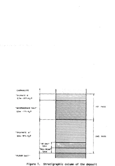
The orebody consists of two sylvinite seams, rather dose to each other, located at 500 m depth. Although thickness values are very variable, average values are shown in figure l. Each sylvinite seam actually consists of many alternating sylvinite and halite seams, a few centimeters thick, with very thin clay seams intercalated. On the other hand, the overall orebody is quite undulated and shows a large number of mullocky areas. Due to the foregoing, the mine profitability is rather tight and so productivity and low ore dilution are of major importance. The Operation is implemented in two successive passes, äs shown in figure l, leaving the carnallite äs roof, and adapting the Operation to the changes in thickness and slope of the seams. Selective cut is performed in every face and, while the ore is conveyed to the extraction shaft, the salt is dumped in the nearby mined rooms.
The mine is currently eguipped with 13 Alpine AM-100 roadheaders which provide a total output of 270,000 tpy K20. The weight of these machines is 95 tons and cutting motor power is 300 kW.
••SVLVINnE B 0 , 7 m - l S - / . K 2 0 "INTERMEOiAIE SALT 2.2B - r». «,0 "SylVINlie A " Vm-f/. K;0
Figure 1. Stratigraphic colunn of the deposit
MINERAL EECOGNITION
Several techniques to discriminate the different Minerals present at the face were tested:
Natural gamma radiation showed poor spatial resolution and difficulties to be installed in the moving cutting head. - Microwave absorption was too much dependent on surface
conditions such äs roughness, water film presence, etc.
- Vibration and noise analysis did not provide possibilities for discrimination in this case.
Finally, vision was selected äs the most convenient technique for this application and so most of the research work was devoted to it.
COMPUTER VISION Spectral Analysis
The feasibility study of vision äs sensing technique started with an spectral analysis of the ores present in the mine. The choice of CCD solid state video cameras äs sensing devices (for robustness, availability, Standard Output and cost reasons) restrained the study to the visible and near infrared ränge of the spectrum, in which those devices are sensitive.
A computer-controlled spectrometric analysis system was set up to measure, störe and process reflectance spectra (between 350 and 1000 nm) from each ore sample in a set of 70 blocks coniposing the complete Stratigraphic column of the mine.
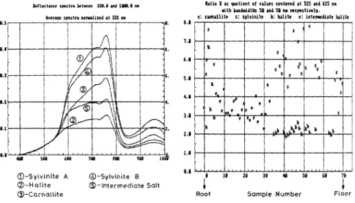
The study concluded that colour differences among the ores depended on spectrum shape, not on its level. Hallte tends to have a higher relative level in the green ränge than sylvinite. Thus, if the spectra are normalized at a proper wavelength, ore classification becomes evident. Figure 2 shows average spectra for five minerals after normalization at 525 nm.
In view of the foregoing, it was decided to define a discrimina-ting value. K, äs the ratio of:
reflectance at 625 + 25 nm
K =
reflectance at 525 + 25 nm
Figure 3 shows the values of K computed for all the spectra. The accuracy of such classification is quite significative although there is overlapping between some sylvinite and intennediate salt samples, and carnallite cannot be separated.
ItriKtrci (KttFI ktifil 1S«.1 VH ISU.I an
Svnw spictra narluliKJ «t 525 nH
«ati» X u wtiNt if nlufs cwtmJ it S2S mi (25 in •ith fcuJudlks Sl inJ Sl nii Ksptctirtla.
c; einullit; s: sgluinitf li: tilit» c iateiwliiti lulili
(D-Sylvinite A © - H a l l t e O-Carnallite ©-Sylvinite B 3 - l n t e r m e d i a t e Salt , , s % s s t '. t
,
h »• ,/ ,' ',.•.
••'.
S ,' s t t^-
-^-s ! f s s s
^
(hl»"-» s i s,^
s s s-^
Figure 2. Normal ized average spectra Figure 3. K values for all samples In order to discriminate the ore distribution in a face it is required to compute the K value at every point. To that end, two monochrome Images should be acquired with narrov passband filters centered at 525 and 625 nm, to be then divided point by point. Another possibility that simplifies camera mechanics is the use of a colour camera, äs the 525 nm and 625 nm filters can be substituted by the in-built green and red filters, with a small degradation of classification accuracy.
Image processing
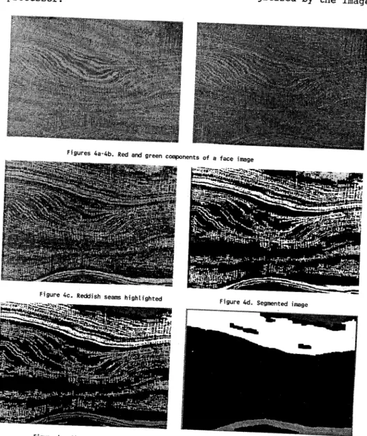
The research on Image processing algorithms was based on a set of Images recorded on videotape in the mine with a Professional colour camera, later decoded to RGB and digitized by the Image processor.
F'gure 4e. Classifjed image
The performance of red/green ratio for direct ore classification of individual pixels was too poor to be effective, because of: - overlapping between K values for the ores, seen in figure 3. - colour variations in cutting head bit marks on the face. ~ noise introduced by camera, recorder and decoder.
Thus, a new processing algorithm was devised to perform classification after region segmentation, to compensate for the variations of pixel colour through averaging. It took advantage of a key characteristic of the orebody: seams of sylvinite, carnallite and intennediate hallte, all of reddish colours, are always flanked by hallte or clay seaas, of unsaturated colours. Region classification was essayed with several techniques, such äs split and merge, freguency domain analysis, Saturation, R/G ratio, and discriminant analysis, which gave best results.
Image processing algorithm was finally composed of three steps:
- Segmentation: the red/green ratio is combined with a quadratic discriminant function to produce an image highiighting reddish seams, which is thresholded and labelled.
- Classification: four quadratic discriminant functions are applied to the original Image over the segmented regions, classifying each of them äs carnallite, A or B sylvinite, or hallte.
- Honogenization: regions are merged, their outlines simplified, and very small regions are reaoved, leaving the main searos.
All the above process is perfomied by Software downioaded on the iiaage processor and executed by its own local microprocessor, leaving the main CPU free for other intensive tasks.
Figure 4 illustrates the typical steps in the process of a face colour Image acquired at the mine.
Inage rusion
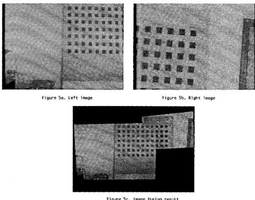
In the roadheader being used, there is no safe location for the caicera which would provide an obstacles-free view of the whole face. Therefore, it was requiered to sep up two cameras at different locations in such way that they cover areas which caiaplement each other. As a result, the data from two cameras, located at different positions, has to be combined into a single Image at some stage of Image processing.
The problem of Images fusion is solved in two stages:
A calibration of the System composed by cameras, roadheader and face is initially carried out to determine the conversion equations between their respective reference Systems, and to estjiriate the distorsion effects of the wide-angle lenses.
Through previous equations, any pair of Images is transferred to the same reference System and the data from both Images is combined in the areas where overlapping exists.
Figure 5 shows an example of Image fusion from two different positions and attitudes, with a plane target surface.
Ffgure 5a. Left Image Figure 5b. R i g h t Image
Fi'gure 5c, Image fusi'on result
Face mapping
Face mapping consists of generating a map of the mineral distribution on a face, in the form of a set of polylines which represent the boundaries between the different seams present in the processed Image.
Once the face most adeguate different for desired final
OPERATION PIANNING
map is produced, a Software module generates the cutting trajectory, which is in principle every new cut. This module takes into account the profile, roadheader operational limitations, and
the constraints imposed by loading procedure, shuttle car capacity, and the mining method itself.
By now, no optimization criteria have been introduced in the operational planning, although the produced trajectory is intended to be an "efficient" one.
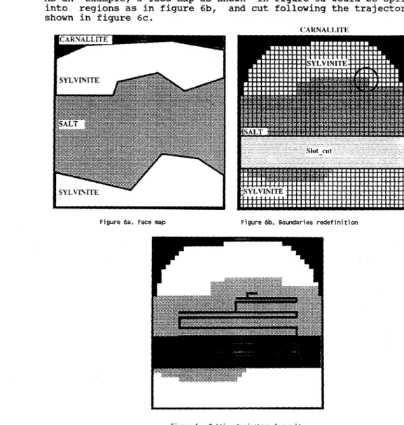
As an example, a face map äs shown in figure 6a would be split into regions äs in figure 6b, and cut following the trajectory shown in figure 6c.
(:ARNA1.1,1TK
Figure 6a. Face map Figure 6b. Boundaries redefinition
Figure 6c. Cutting trajectory for salt
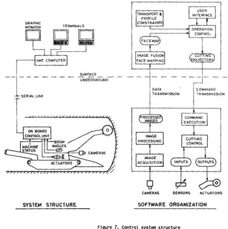
CONTROL SYSTEM STRUCTURE
The control System is based on a double-computer configuration: a real-time control unit located on the roadheader, and a main unit located outside the mine, in communication through a serial link 4 km long, äs shown in figure 7.
CAMERAS SENSOBS ACTUATORS
SOFTWARE ORGANIZAT10N SYSTEM STRUCTURE
Figure 7. Control System structure
The control unit located at the machine is a diskless VMEbus industrial Computer dedicated to acquisition and process of all data frorn cameras and sensors, and execution of machine control commands and cutting schedules received from the main unit, through actuators on electric and hydraulic equipment. This unit incorporates dedicated hardware such äs an Image processor and analog/digital I/O and communications boards. The unit is well protected against impacts and vibrations and is equipped with an uninterrupted power supply and its own cooling System since the environmental temperature stays around 37°C.
The main unit at the surface is a VMEbus industrial Computer running UNIX dedicated to Software development work, remote system monitoring and Operation planning and control. To start the system, the main unit downioads the different Software modules to the Underground unit, until the system is up and running. In this first test, however, the system was controlled frorn the man-machine interface at the Underground unit.
MINE TEST
Conditions in the mine where system test has been conducted were hard, due to the dusty and saline environment, high temperature and distance from the surface. Time available for tests could not be äs long äs desired, but has been enough to find out the actual possibilities and limitations of the system.
The basic problem found in the mine test was the low quality of the Images provided by the video cameras, mainly due to insufficient resolution and poor colour quality (most seams of the face are very thin compared to pixel size), which could not be properly processed by the vision system. But in the developing industrial camera market, probably new products will soon appear providing adequate quality at an affordable price.
Positive results were obtained with:
- Image acquisition: worked well in terms of camera positioning and face coverage, although stronger mechanical protection for cameras and lighting is required.
- Image processing: füll mineral identification process worked successfully on the onboard Computer with videotaped images. - Other programs: camera calibration, image fusion, face mapping
and trajectory planning programs were tested on the surface Computer at the laboratory.
- Trajectory execution and control: worked well although horizontal movement needs adjustment due to nonlinear boom hidraulics behaviour.
- Software structure developed for Underground unit based on VERSADOS real-time multitasking kernel operated successfully. - System hardware: worked properly without major problems,
although the protection of some sensors should be improved. - Communication link between Underground and surface Computers
could not be fully debugged to achieve expected data rate.
FUTÜRE WORK
A grant has recently been approved by the Commission of the European Community (DG XII) to develop a second phase of this research project. The aims in this new phase are basically to continue with the development, solving the problems found in the previous one and refining the Systems and programs produced to make them more robust and less dependent on particular conditions.