HAL Id: tel-00259507
https://tel.archives-ouvertes.fr/tel-00259507
Submitted on 28 Feb 2008HAL is a multi-disciplinary open access archive for the deposit and dissemination of sci-entific research documents, whether they are pub-lished or not. The documents may come from teaching and research institutions in France or abroad, or from public or private research centers.
L’archive ouverte pluridisciplinaire HAL, est destinée au dépôt et à la diffusion de documents scientifiques de niveau recherche, publiés ou non, émanant des établissements d’enseignement et de recherche français ou étrangers, des laboratoires publics ou privés.
Etude expérimentale des régimes de combustion d’un feu
de compartiment dans des conditions de sous-ventilation
Anthony Edwin Pearson
To cite this version:
Anthony Edwin Pearson. Etude expérimentale des régimes de combustion d’un feu de compartiment dans des conditions de sous-ventilation. Energie électrique. Université de Poitiers, 2007. Français. �tel-00259507�
THÈSE
pour l’obtention du grade de
D
OCTEUR
de
l’U
NIVERSIT
É
de
P
OITIERS
École Nationale Supérieure de Mécanique et d’Aérotechnique&
Faculté des Sciences Fondamentales et Appliquées (Diplôme National – Arrêté du 7 août 2006)
École Doctorale Sciences pour l’Ingénieur et Aéronautique Secteur de Recherche : Énergie, Thermique, Combustion
Présentée par :
Anthony Edwin P
EARSON
*********
ÉTUDE EXPÉRIMENTALE DES RÉGIMES DE
COMBUSTION D’UN FEU DE COMPARTIMENT DANS
DES CONDITIONS DE SOUS-VENTILATION
EXPERIMENTAL STUDY OF THE COMBUSTION
REGIMES OF A COMPARTMENT FIRE UNDER
CONDITIONS OF UNDERVENTILATION
*********
Directeurs de thèse : Jean-Michel M
OSTet David Douglas D
RYSDALE*********
Soutenue le 6 Février 2007 devant la Commission d’Examen
********** - JURY -
M. F. PENOT Directeur de Recherche CNRS au LET, Poitiers Président
M. A. COPPALLE Professeur au CORIA, Rouen Rapporteur
M. B. KARLSSON Professeur à l’Université d’Islande, Reykjavik Rapporteur
M. D. DRYSDALE Professeur à l’Université d’Edimbourg, Ecosse M. J.-M. MOST Directeur de Recherche CNRS au LCD, Poitiers
THÈSE
pour l’obtention du grade de
D
OCTEUR
de
l’U
NIVERSITÉ
de
P
OITIERS
École Nationale Supérieure de Mécanique et d’Aérotechnique
&Faculté des Sciences Fondamentales et Appliquées
(Diplôme National – Arrêté du 7 août 2006)École Doctorale Sciences pour l’Ingénieur et Aéronautique Secteur de Recherche : Énergie, Thermique, Combustion
Présentée par :
Anthony Edwin P
EARSON
*********
ÉTUDE EXPÉRIMENTALE DES RÉGIMES DE
COMBUSTION D’UN FEU DE COMPARTIMENT DANS
DES CONDITIONS DE SOUS-VENTILATION
*********
Directeurs de thèse : Jean-Michel M
OSTet David Douglas D
RYSDALE*********
Soutenue le 6 Février 2007 devant la Commission d’Examen
********** - JURY -
M. F. PENOT Directeur de Recherche CNRS au LET, Poitiers Président
M. A. COPPALLE Professeur au CORIA, Rouen Rapporteur
M. B. KARLSSON Professeur à l’Université d’Islande, Reykjavik Rapporteur
M. D. DRYSDALE Professeur à l’Université d’Edimbourg, Ecosse M. J.-M. MOST Directeur de Recherche CNRS au LCD, Poitiers M. P. ROUSSEAUX Professeur à l’Université de Poitiers
Acknowledgements
Any PhD project relies on a triangular relationship between the student, the supervisors and the financiers.
I have had a rather high turnover rate of supervisors during the years I have been working towards the creation of this thesis. Prof Dougal Drysdale from the University of Edinburgh has been with the project from the outset, providing the benefit of his experience, unflappability, optimism and wide-ranging knowledge on all aspects of fire safety engineering and science. Doctor Asif Usmani accompanied me for the first few months as co-supervisor, acting as a second source of patience and optimism. After growth and restructuring of the Fire Safety Research Group at the University of Edinburgh, the role of co-supervisor was passed to Prof José Torero, a seemingly endless fountain of knowledge and important source of moral support. Prof Bill Easson was added to the team, officially only as “Supervision Assistant”, but that description that does not do justice to the technical aid and tuition he provided. The French Connection in the project was directed by Dr Jean-Michel Most, providing the benefit of his constant availability whenever help was needed, his experience in writing reports and papers and his generosity (not to mention his cooking).
As for the financial support, I am indebted to my parents not only for the moral support that one comes to take for granted, but also for a five-digit sum of hard currency. To their relief, I had the fortune to receive a grant from the US National Fire Protection Association and then later obtain funding from the Firenet research network financed by the European Union – a project which not only provided a generous grant, but also much opportunity to collaborate with other key people in the field of fire safety research. In particular, valuable help was gained via the network from Profs Colomba di Blasi, Mike Delichatsios and Jennifer Wen, and Drs
Remerciements
Tout projet de thèse est basé sur une relation triangulaire entre l’étudiant, les encadrants et les financiers.
Mon taux d’usage d’encadrants était assez haut pendant les années où j’ai travaillé sur ce projet. Prof Dougal Drysdale de l’Université d’Edimbourg a suivi le projet dès le début, et j’ai pu profiter de son expérience, son imperturbabilité, son opti-misme et son savoir vaste sur l’ensemble du domaine de la sécurité incendie. Dr Asif Usmani m’a accompagné pendant les premiers mois comme co-directeur de thèse, et était une deuxième source de tranquillité et d’optimisme. Suite à l’élargissement et à la réorganisation de l’équipe de recherche de sécurité incendie à l’Université d’Edim-bourg, le rôle de co-directeur est passé au Prof José Torero, une source, comme il semble, inexhaustible de savoir et une source importante de soutien moral. Prof Bill Easson a été ajouté à l’équipe, officiellement comme « Assistant de Direction », mais cette description ne rend pas compte à l’aide technique et la formation qu’il m’a offertes. Le côté français du projet a été dirigé par Dr Jean-Michel Most, qui m’a fait profiter de sa disponibilité quasiment constante quand il y avait besoin d’aide, de son expérience dans l’écriture des rapports et des articles et de sa générosité (sans parler de sa cuisine).
Pour le soutien financier, je suis rede-vable à mes parents, non seulement pour le soutien moral dont on profite sans demander, mais aussi pour une somme d’argent de cinq chiffres. J’ai ensuite eu la chance de recevoir une bourse de la National Fire Protection Association aux Etats-Unis, et plus tard j’ai obtenu une bourse par le réseau Firenet, financée par l’Union Européenne. Ce réseau ne m’a pas seulement offert une bourse généreuse, mais également beaucoup d’opportunités de collaborer avec des per-sonnes dans le cadre mondial de la recherche sur la sécurité incendie. En particulier, j’ai reçu de l’aide importante par le réseau des
Carmen Branca, Andrej Horvat and Yehuda Sinai
I would like to thank Profs Alexis Coppalle, Björn Karlsson and Patrick Rousseaux, and Dr François Penot for accepting the task of reviewing and judging my work.
An experimental project as complicated as the one described in this document would not get very far without assistance from the technical staff who provide many ideas, but whose names rarely figure in the lists of authors of any reports. I would like to thank Neil Wood and Jacques Baillargeat for retaining their humour when faced with requests to do the impossible, Jean-Paul Bigeau for his patience after the countless times I broke the fruits of his labour, Pascal Grelier for finding better ways of constructing the objects I asked him to build, Alain Claverie for ensuring that I did not repeat the operational errors of an anonymous student in Edinburgh which were behind my being moved to France, Cécile Losier for being a rich source of ideas, and Kevin Anderson, Véronique Bertin, Daniel Falaise and Yves Foy for their skilled work in their respective fields.
The advice of people who previously worked on a project is of course also invaluable; Drs Davoud Ahmadyar, Mickaël Coutin, Gérald Débenest and Jean-Marc Rousset provided the benefit of their experience. I am also indebted to Dr Bertrand Poireault and to Gilles Bertin and Jérôme Ricola: although I have not had the honour to meet these gentlemen, the reports they left behind describing the work they performed at the LCD before I arrived aided my understanding of the history of the project.
During the first months in Poitiers I had the good fortune to work alongside Yann Beaumin, who provided many an idea and for whose presence during the initial experimental work aided the assurance of safe working practice (No I wasn’t trying to kill you when I singed your hair).
Profs Colomba di Blasi, Mike Delichatsios et Jennifer Wen, et des Drs Carmen Branca, Andrej Horvat et Yehuda Sinai.
J’aimerais remercier les Profs Alexis Copalle, Björn Karlsson et Patrick Rous-seaux, et Dr François Penot pour avoir accepté de relire et de juger mon travail.
Un projet expérimental si complexe que celui décrit dans ce document ne serait pas possible sans l’aide du personnel technique qui fournit beaucoup d’idées mais qui ne figure que rarement dans les listes d’auteurs de rapports. J’aimerais remercier Neil Wood et Jacques Baillargeat pour avoir gardé leur humour quand je leur ai passé des demandes pour faire l’impossible, Jean-Paul Bigeau pour avoir gardé sa patience après toutes les fois où j’ai cassé ses constructions, Pascal Grelier pour avoir trouvé de meilleurs façons de construire les pièces que je lui ai demandées de produire, Alain Claverie pour avoir assuré que je n’ai pas répété les erreurs d’un étudiant anonyme à Edimbourg qui sont la raison pourquoi je suis venu en France, Cécile Losier pour ses idées, et Kevin Anderson, Véronique Bertin, Daniel Falaise et Yves Foy pour leur travail de spécialiste.
Les conseils des gens ayant déjà travaillé sur un projet sont bien sûr aussi très précieux. Drs Davoud Ahmadyar, Mickaël Coutin, Gérald Debenest et Jean-Marc Rousset m’ont fait profiter de leur expé-rience. Je suis également redevable de Dr Bertrand Poireault et de Ms. Gilles Bertin et Jérôme Ricola ; je n’ai jamais rencontré ces messieurs, mais les rapports qu’ils ont laissés de leurs travaux avant mon arrivée au LCD m’ont aidé à comprendre la trame de fond du projet.
Pendant mes premiers mois à Poitiers, j’ai eu la chance de travailler à côté de Yann Beaumin, qui a fourni beaucoup d’idées et qui a aidé à assurer un fonctionnement sécurisé dans la salle d’expérience (quand je t’ai brûlé les cheveux, ce n’était pas une tentative pour te tuer).
La collaboration internationale pendant
The international collaboration which was set up during the project provided unusual challenges to the administrative staff. The secretaries, particularly Ruth Khan and Jocelyne Bardeau, provided immea-surable practical help, moral support and humour. I owe more debt than most of the ENSMA’s PhD students to Corinne Dutault and the Scolarité team at the ENSMA, to Martine Lafont and to Sylvie Perez and the
Scolarité team at the faculty offices in
Poitiers for their flexibility and humour in tackling whatever complications landed at their respective doors.
I would like to thank Profs Andrew Barry, Pascal Bauer, Yves Bertrand, Peter Grant, Francis Roger and Claude Templier, and Drs Michel Champion, Pierre Joulain and Henri-Noël Presles for their tireless work at the unrewarding task of getting the scientists in their respective institutions to work together as a team.
I would also like to express my gratitude to Dr Patrice Remaud and to François Baty-Sorel for providing much more than just lectures.
The people I met, too numerous to list, during the seminars, conferences and meetings I attended since starting the project were a source of inspiration and hope for the future of fire safety science.
The sanity of any PhD student depends heavily on the support he or she obtains from his or her fellow students. I owe my gratitude to all who have passed my way during the course of the project. The following deserve particular mention. Drs Jo Sherrat and Kuang Chung Tsai who shared their office with me in Edinburgh, showed me the ropes and pointed out that any problems I may experience are nothing compared to what they had had to deal with. Dr Tim Andzi Barhé took me under his wings during the first years at Poitiers and provided immeasurable moral support. Dr Philipp Bauer provided many an idea and useful technical and computing support. Dr Gabriel
le projet a donné des défis particuliers pour le personnel administratif. Les secrétaires, en particulier Ruth Khan et Jocelyne Bardeau, ont offert de l’aide pratique, du soutien moral et un humour incommensurable. Je dois beaucoup plus que le plupart des thésards de l’ENSMA à Corinne Dutault et l’équipe de la Scolarité à l’ENSMA, à Martine Lafont et à Sylvie Perez et l’équipe de la Scolarité de la Faculté SFA à Poitiers pour leur flexibilité et leur humour dans la résolution de toutes les complications qui leur sont tombées dessus.
J’aimerais exprimer ma gratitude envers les Profs Andrew Barry, Pascal Bauer, Yves Bertrand, Peter Grant, Francis Roger et Claude Templier, et les Drs Michel Champion, Pierre Joulain et Henri-Noël Presles pour leur travail dans la tache ingrate de faire travailler comme collectif les scientifiques dans leurs institutions respec-tives.
J’aimerais également remercier Dr Patrice Remaud et François Baty-Sorel pour ne pas avoir que donné des cours.
Les personnes, trop nombreuses pour être citées ici, que j’ai rencontrées pendant les séminaires, conférences et réunions auxquelles j’ai assisté, ont été une source d’inspiration et d’espoir pour l’avenir de la science de sécurité incendie.
La santé mentale d’un thésard dépend fortement du soutien qu’il ou elle reçoit des autres étudiants. Je dois une gratitude à tous ceux qui ont croisé mon chemin pendant le projet. Les suivants méritent particulièrement d’être nommés : Drs Jo Sherrat et Kuang Chung Tsai qui ont partagé leur bureau à Edimbourg avec moi, qui m’ont introduit dans le travail de recherche et qui ont montré que tout problème que je pourrais avoir n’est rien comparé aux difficultés qu’ils ont eues. Dr Tim Andzi Barhé m’a accompagné pendant les premiers mois à Poitiers et m’a donné un soutien moral inestimable. Dr Philipp Bauer m’a fourni avec beaucoup d’idées et donné du soutien avec l’infor-matique. Dr Gabriel Canteins a joué un rôle
Canteins played a key part in bringing us students together to form a social group rather than remaining collection of indivi-duals. Dr Rui Rego and soon-to-be-Dr Weylong Siauw provided invaluable support simply by showing that one can remain calm and composed despite all the hardships. Drs and not-yet-Drs Sébastien Bourgois, Bastien Boust, Fabien Chassagne, Yun Chi Chung, Max Clarke, Cony Dörich, Hazem El Rabii, Olivier Esnault, Sergio Ferraris, Andrès Fuentes, John Grondin, Georges Guigay, Vianney Guilly, Nicolas Henneton, Larbi Jabine, Stephen Johnson, Susan Lamont, Yu Ying Liu, Bernardo Martinez, Raphael Meyrand, Phu Khan Nguyen, Laurence Pagnanini, Scott Rodgers, Yussef Roudani, Jacques Tézanou, Piotr Tofilo, and Mmes Elena Chouteau and Ioana Magda all provided many an hour of company.
Finally, I owe a lot to those who provided me with space to escape occasionally from the ivory tower and communicate with the rest of humanity. The staff at the fire station in Jaunay Clan entertained me for many an hour and provided fascinating insight into the business side of fire safety in France. The Scout Association in the UK and the Eclaireuses Eclaireurs de France provided me with much support without which I don’t know how I would have coped. I am convinced that the friendship, training, leadership experience and moral support I gained during my time in Scouting outweigh the benefit the Scout Movement received from me. I would like to thank everyone I met in Scouting for the experience and friendship, particularly the teams of the 75th, 85th, 98th and 139th Groups in Edinburgh, Blackford District Leadership, Edinburgh Area Leadership, the OASIS team in Edinburgh, the team of the Poitiers Group, Aquitaine-Poitou-Charentes Regional Lea-dership, but equally the Beavers, Cubs, Scouts, Venture Scouts, trainee Leaders and parents who allowed me the privilege of working with them. Particular mention is due to Chantal Cherrier, Dr Louise Fromard,
clé pour faire que nous étudiants formions un groupe social au lieu de rester une collection d’individus. Dr Rui Rego et bientôt-Dr Weylong Siauw m’ont donné du soutien tout simplement en montrant qu’il est possible de rester calme malgré les difficultés. Drs et pas-encore-Drs Sébastien Bourgois, Bastien Boust, Fabien Chassagne, Yun Chi Chung, Max Clarke, Cony Dörich, Hazem El Rabii, Olivier Esnault, Sergio Ferraris, Andrès Fuentes, John Grondin, Georges Guigay, Vianney Guilly, Nicolas Henneton, Larbi Jabine, Stephen Johnson, Susan Lamont, Yu Ying Liu, Bernardo Martinez, Raphael Meyrand, Phu Khan Nguyen, Laurence Pagnanini, Scott Rodgers, Yussef Roudani, Jacques Tézanou, Piotr Tofilo, et Mmes Elena Chouteau and Ioana Magda ont tous donné beaucoup d’heures de leur temps en ma compagnie.
Enfin, je dois beaucoup à ceux qui m’ont donné de l’espace pour sortir parfois de la tour d’ivoire et pour communiquer avec le reste de l’humanité. Le corps du centre de secours et d’incendie de Jaunay Clan m’a offert beaucoup d’heures de divertissement et m’a montré le fonctionnement du côté pratique de la sécurité incendie en France. La Scout Association en Grande-Bretagne et les Eclaireuses Eclaireurs de France m’ont apporté beaucoup de soutien, sans lequel je ne vois pas comment j’aurais pu aller au bout. Je suis convaincu que l’amitié, la formation, l’expérience et le soutien moral que j’ai reçus pendant le temps dans le Scoutisme valent plus que ce que le Mouvement Scout a reçu de moi. J’aimerais remercier tous ceux que j’ai rencontrés aux Scouts et Eclaireurs pour l’expérience et l’amitié, en particulier les équipes des 75me, 85me, 98me et 139me Groupes à Edimbourg, l’équipe de District de Blackford, l’équipe régionale d’Edimbourg, l’équipe du Groupe de Poitiers et l’équipe régional Aquitaine-Poitou-Charentes, mais aussi les Castors/ Lutins, Louveteaux, Eclaireuses/eurs, Aîné(e)s, stagiaires en animation et parents qui m’ont donné le privilège de travailler
Edwin Maxwell, Wayne Pearson (no relation to the author), Frank Reynolds and Véro Sapin for the invaluable moral support they provided.
avec eux. Chantal Cherrier, Dr Louise Fromard, Edwin Maxwell, Wayne Pearson (aucune relation avec l’auteur), Frank Rey-nolds et Véro Sapin méritent particu-lièrement d’être cités pour le soutien moral inestimable qu’ils m’ont offert.
Table of Contents
Résumé ... 15
Symbols and Abbreviations... 23
1 Introduction ... 27
1.1 Background ... 27
1.2 Literature Review ... 30
1.2.1 The Combustion Process... 30
1.2.2 Fires in the Open ... 33
1.2.3 Compartment Fires... 35
1.2.3.1 Fires in Very Well Ventilated Compartments... 35
1.2.3.2 Fires in Compartments with “Normal” Ventilation ... 37
1.2.3.3 Underventilated Compartment Fires ... 47
1.2.3.4 Special Cases... 50
1.2.4 Fires with Raised Fuel Sources ... 52
1.3 Aims ... 57
1.4 Contents of this Report... 58
2 Experimental Apparatus ... 59
2.1 Compartments ... 60
2.1.1 Bertin Compartment... 60
2.1.2 “Telephone Box”... 63
2.2 Fuel Sources ... 64
2.2.1 Use of Gas Burners to Simulate Solid or Liquid Fuels ... 64
2.2.2 Burners used in the Study... 66
2.2.2.1 Porous Burner... 66
2.2.2.2 Line Burner ... 68
2.2.2.3 Sand-Bed Burner ... 68
2.2.3 Gas Supply ... 70
2.3 Measurements performed and Diagnostics used ... 71
2.3.1 Imaging of Flame ... 71
2.3.2 Velocity Measurements ... 72
2.3.2.1 Equipment ... 73
2.3.2.2 Velocity Field around the Burner... 76
2.3.2.3 Velocity Field around the Edge of the Flame... 78
2.3.2.4 Vent Flow Rate ... 80
2.3.3 Temperature Measurement... 82
2.3.4 Chemical Analysis... 83
2.3.5 Area Covered by the Flame... 85
2.3.5.1 Aims and Concept ... 85
2.3.5.2 Technology used to measure the area covered by the flame ... 87
2.4 Operating Procedure... 90
2.4.1 Ignition Procedure ... 90
2.4.2 Time to Steady State ... 91
3 Results and Discussion ... 97
3.1 Observation of Shape and Behaviour of the Flame... 97
3.1.1 Overview ... 98
3.1.2 Flame Shape and Behaviour... 98
3.1.2.1 Generalities ... 98
3.1.2.2 Blue Partial Interface Flames ... 102
3.1.2.3 Yellow Full Interface Flames ... 103
3.1.3 Extinction ... 104
3.2 Aerodynamics, Flame Structure and Stability... 104
3.2.1 Velocity Field at the Exit of the Burner ... 105
3.2.2 Velocity Field around the Edge of the Flame... 106
Motion of the Flame Edge... 108
3.2.2.1 Velocity Field relative to the Flame ... 108
3.2.3 Temperature Field ... 110
3.2.3.1 Temperature Histories ... 110
3.2.3.2 Maps of Average Temperatures ... 112
3.2.4 Chemical Makeup of the Upper Layer ... 116
3.2.5 Tests with Methane as Fuel ... 118
3.2.6 Discussion ... 118
3.2.6.1 Flow Pattern ... 118
3.2.6.2 Flame Structure ... 120
3.2.6.3 Flame Stability ... 121
3.2.6.4 Presence of External Flaming ... 123
3.2.6.5 Influence of Fuel and Comparison with Morehart’s Configuration... 123
3.3 Analysis of the Area Covered by the Flame... 124
3.4 Influence of the Ventilation on the Behaviour of the Flame ... 134
3.4.1 Description of the Behaviour ... 134
3.4.2 Layer Depth ... 137
3.4.3 Minimum Fuel Flow Rate ... 140
3.4.4 Temperatures ... 143
3.4.5 Vent Flow Rate... 145
3.4.6 Discussion ... 151
3.4.6.1 Ventilation Regime ... 151
3.4.6.2 Extinction ... 153
4 Conclusion... 163
References ... 167
Annexe – Estimate of the Heat Losses ... 171
Basic Assumptions and Input Values... 171
Temperatures... 171
Material Properties ... 172
Heat Losses through Walls... 174
Convective Heat Transfer through the Vent... 177
References ... 178
Résumé
1 Introduction
Lors des dernières décennies, un nombre important de recherches a été consacré aux feux libres ou confinés dans des compartiments. Ces études ont permis de faire évoluer les simulations numériques et d’obtenir des outils d’analyse de sûreté performants. Malgré cela, les incendies restent toujours synonymes de cause majeure de dégâts matériels et de pertes de vies humaines.
Les feux de compartiment présentent des comportements très variés qui dépendent principalement de la nature, de la position du combustible ainsi que de la ventilation de l’enceinte. Une partie de la chaleur dégagée par la flamme et des produits de combustion peut être piégée en dessous du plafond ce qui augmente le flux de chaleur vers les sources de combustible disponibles qui s’embrasent alors.
La plupart des recherches sur les feux de compartiment a porté sur des configurations dans lesquelles la source de combustible était positionnée sur, ou à proximité du sol. Par contre, peu d’informations sont disponibles sur le comportement d’un feu lorsque la source de combustible est dans une zone sous-ventilée. L’étude d’un tel scenario reste une priorité au Laboratoire de Combustion et de Détonique (LCD) dans le contexte du risque incendie dans les installations à ventilation contrôlée. De tels édifices posent des problèmes spécifiques quant à la sécurité d’incendie, la ventilation est réglée pour que les effluents, souvent polluants et toxiques, ne puissent être rejetés directement dans l’environnement.
Lors d’un précédent projet, des tests préliminaires ont été effectués en simulant partiellement, grâce à l’injection d’un hydrocarbure gazeux à travers un brûleur, la dégradation d’un combustible solide ou l’évaporation d’un combustible liquide. Cette simulation a permis à l’expérimentateur de décorreler le débit de combustible du flux de chaleur transmis des produits de combustion vers la source de combustible. Le dispositif expérimental consiste en une enceinte munie d’un linteau afin de piéger une couche chaude de fumées et de produits de combustion dans sa partie haute. Si le brûleur de simulation est en position basse dans l’enceinte, un panache de feu susceptible d’interagir avec la zone chaude se forme au-dessus du brûleur. Si le brûleur est placé en proximité de l’interface entre la couche supérieure de fumées et la couche d’air inférieure, l’entraînement d’air dans le panache ne va suffire que pour une combustion incomplète dans ce dernier, et par conséquent
du combustible imbrûlé va être transporter vers la couche supérieure, ce qui peut mener à l’apparition de flammes à l’interface entre les couches. Si le brûleur est maintenant placé dans la couche supérieure, et avec un faible débit de combustible, la flamme s’éteint. Pour de plus forts débits de gaz la flamme se détache du brûleur et se stabilise à l’interface entre les couches. Selon le débit de combustible, il est observé soit des flammes jaunes cellulaires couvrant toute l’interface, soit des flammes bleu-jaunes dont le taille fluctue sur une partie de l’interface.
Le but de ce travail de thèse est de compléter nos connaissances sur le comportement des feux quand la source de combustible est située dans la zone chaude piégée par le linteau. Les objectifs suivants ont été recherchés :
• l’identification des mécanismes qui permettent à la flamme de se stabiliser à l’interface entre les deux couches ;
• l’étude de l’influence du type de combustible, de son débit (et donc la puissance calorique théoriquement dégagée), de la hauteur du linteau et de la taille de l’ouverture en dessous du linteau sur les régimes de flamme contrôlés par le débit de combustible ou par le débit d’air entrant.
2 Installation expérimentale
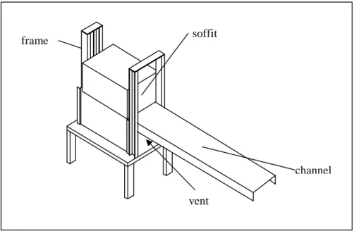
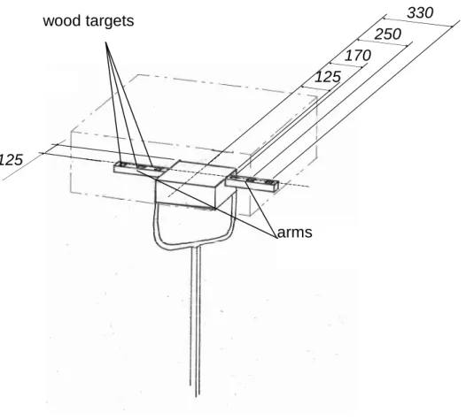
Cette recherche a été menée dans un compartiment à l’échelle de laboratoire (0.62 m de long, 0.84 m de haut, 0.40 m de large). Deux linteaux différents de hauteurs respectives 0.19 m et 0.34 m sont installés à tour de rôle au dessus de l’ouverture pour piéger une couche de fumées et de produits de combustion capable de rayonner et enflammer des cibles combustibles. Des panneaux isolants de différentes tailles sont utilisés pour modifier le facteur de ventilation FV en changeant la forme et la surface de l’ouverture.
La surface de la flamme à l’interface des zones chaude et froide est considérée comme une grandeur représentative de régime de flamme. Pour permettre la détermination de cette surface et la comparaison de sa partie à l’intérieur avec sa partie à l’extérieur de l’enceinte, il faut que les deux parties soient horizontales pour que l’entraînement d’air dans les deux parties soit semblable. Pour affecter ceci, un canal horizontal, ouvert en partie inférieure, a été installé à la sortie de l’enceinte.
Des brûleurs à gaz alimentés en propane ou méthane sont utilisés pour introduire du combustible gazeux dans l’enceinte.
Plusieurs différentes techniques de diagnostique ont été utilisées pour décrire la flamme, son mode de stabilisation et son régime.
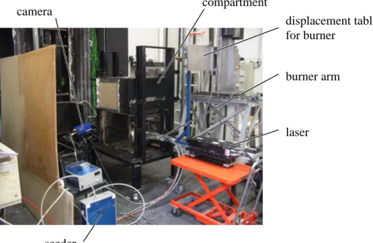
Des visualisations optiques et la capture d’images au moyen de caméscopes numériques ont permis d’enregistrer la dimension et la couleur des flammes ainsi que la taille des couches inférieure et supérieure. Avec l’aide d’une caméra numérique et d’un traitement des images, la surface couverte en moyenne par la flamme en fonction des paramètres a été déterminée.
Des mesures de champs de vitesse ont été effectuées à trois endroits différents par vélocimétrie d’images de particules (PIV). D’abord le champ aérodynamique dans la zone de l’orifice du brûleur a été enregistré. Ensuite des relevés ont été effectués près du bord d’attaque des flammes. Afin de pouvoir corréler l’écoulement avec la position de la flamme, le temps d’exposition de la caméra PIV a été réglé pour capturer à la fois la lumière du plan de laser diffusée par les particules d’ensemencement (diffusion de Mie) et la lumière de la flamme (émission spontanée). Finalement le champ de vitesse dans l’ouverture a été mesuré afin de calculer le débit d’air entrant dans l’enceinte.
Un peigne de thermocouples détermine le champ de température moyen dans l’enceinte. Des prélèvements de gaz dans la zone supérieure de l’enceinte ont été effectués pour déterminer la composition chimique du milieu par une analyse chimique, soit par chromatographie en phase gazeuse, soit par des analyseurs en ligne pour les espèces stables majoritaires.
3 Résultats et Discussion
3.1 Observation de la forme et du comportement de la flamme
Dans le compartiment deux couches de produits différents sont bien identifiées : une couche d’air frais dans la partie basse, et une couche riche en combustible dilué dans des produits de combustion et pauvre en oxygène en partie haute piégée par le linteau.
Pour des débits de combustible m&F importants (> 0.65
g
/s, ce qui correspond à une
puissance calorique H& de 30 kW), une flamme jaune cellulaire est observée, elle couvre toute
l’interface de l’enceinte entre les deux couches. Pour des débits de combustible plus faibles, la flamme se détache des parois et présente une taille fluctuante ; en même temps, elle change de couleur pour prendre un aspect complètement bleue pour des valeurs de m&F inférieures à 0.27
g
/s (13 kW). Si le débit de combustible est encore plus réduit, les fluctuations de taille
deviennent plus importantes, jusque un seuil de 0.21 g/s, en dessous duquel la flamme ne peut
pas être maintenue et s’éteint.
Dans l’enceinte les couches inférieure et supérieure sont thermiquement stables. Par contre, une instabilité thermique entre la flamme (plus chaude) et la couche supérieure moins chaude se manifeste à cause des pertes au travers des parois. Ceci explique l’aspect cellulaire de la flamme : à cause des effets de flottabilité, les gaz dans la zone de réaction sont entraînés vers le haut et une partie de ceux-ci pénètre dans la couche supérieure induisant un mouvement convectif.
3.2 Aérodynamique ; structure et stabilité de la flamme
Le champ de vitesse dans la zone à proximité de l’orifice du brûleur montre que le combustible sortant du brûleur s’écoule le long du plafond puis vers l’arrière de l’enceinte pendant que des gaz et des fumées de la couche viciée sont entraînés vers le haut et recirculent. On peut alors supposer que, dans ce vortex de recirculation, le combustible se mélange et se dilue dans des produits de combustion de la couche supérieure.
Le champ de vitesse en amont du liséré d’une flamme d’interface ne recouvrant pas la totalité de la surface, montre que le fluide aborde la flamme horizontalement, est ensuite dévié vers le haut, puis continue parallèlement à la flamme. La vitesse moyenne au bord d’attaque de la flamme est 0,3 m/s ce qui est de l’ordre de grandeur de la vitesse de propagation
théorique d’une flamme de prémélange laminaire – la valeur exacte de la vitesse de propagation théorique ne peut pas être déterminée avec précision, car la température et la composition chimique en amont de la flamme sont inhomogènes et difficiles à mesurer.
La température dans la couche supérieure est dans l’ordre de 500°C. Pour un plus fort débit de combustible, la température dans la couche viciée augmente jusqu’à ce que la flamme couvre toute la surface de l’interface. La température devient alors indépendante du débit de combustible et de la taille de la ventilation.
L’analyse chimique dans la couche supérieure montre la forte dilution du combustible dans des produits de combustion : on obtient une concentration de 23 % en produits de combustion (CO2, H2O), 6 % en combustibles divers et 2 % en oxygène. Les 69 % restant
étaient de l’azote. En amont de la flamme, le combustible est donc dilué dans les produits de combustion.
Ces résultats indiquent que lorsque la flamme ne couvre que partiellement la surface de l’enceinte, un mécanisme de flamme triple stabilise la combustion – une zone de mélange se forme entre le combustible dilué dans des produits de combustion en partie supérieure et l’air en partie inférieure. Ce prémélange, à richesse variable, autoentretient la réaction chimique ; le front de flamme se propage à contre courant de l’écoulement vers le fond de l’enceinte. En aval de ce front la majorité des réactifs brûlent dans une flamme de diffusion.
La surface de la partie de la flamme à l’intérieur de l’enceinte et la stabilité de la combustion sont liées au rapport entre la vitesse l’écoulement en amont de la flamme, vgaz, et la vitesse de propagation de la flamme de prémélange, SL, vitesse caractéristique de la flamme laminaire. Si SL est supérieure à vgaz, la flamme se propage vers le fond de l’enceinte. Inversement, si SL est inférieure à vgaz, la surface de la flamme diminue. Une augmentation du débit de combustible mène à une augmentation de sa concentration dans les produits de combustion ainsi que de la température, et par conséquent à une augmentation de SL : donc, la surface moyenne de la flamme augmente et la combustion devient plus stable. Les fluctuations de la surface de la flamme qui sont observées sont attribuées à des variations de concentrations, de température et de vitesse d’écoulement en amont du front. Au dessus d’un certain seuil de débit de combustible, l’équilibre entre les deux vitesses n’est plus atteint et la flamme recouvre toute la surface.
La couleur bleue de la flamme (émission des radicaux d’hydrocarbures) vient du fait que peu de suies sont formées. Si le débit de combustible augmente (forte dilution du combustible), la concentration en combustible dans la zone haute augmente ; la température de flamme augmente, d’où une production plus importante de suies.
3.3 Analyse de la surface couverte par la flamme
Il a été démontré que la surface couverte par la flamme n’est pas directement proportionnelle à la chaleur dégagée, mais qu’il faut considérer la surface en fonction du débit de combustible diminué du débit minimal pour assurer la combustion, Afl
(
m&F −m&F−min)
. La surface est par ailleurs liée à la chaleur convective Q&conv, c’est à dire la chaleur dégagéediminuée des pertes thermiques
(
Q& −Q&loss)
.Tant que la combustion reste contrôlée par la disponibilité en combustible, la surface couverte par la flamme est indépendante du facteur de ventilation FV. Ce critère sur la surface de flamme est quantifié pour le débit de combustible par unité de surface de flamme, qui relie alors le comportement de la combustion au flux de combustible moyen atteignant l’interface et brûlant dans la flamme d’interface.
Pour qu’une extinction se produise, c’est-à-dire l’impossibilité de maintenir la combustion, arrive, au moins un des deux critères suivants doit être rempli :
que la vitesse de propagation du front de prémélange SL soit inférieure à la vitesse de l’écoulement amont,
que la concentration de combustible soit insuffisante pour maintenir une flamme de diffusion.
Pour pouvoir prédire le comportement dans des telles configurations, mais à d’autres échelles, il est important de trouver des paramètres caractéristiques qui lient les valeurs critiques du débit de combustible avec la géométrie. Un comparaison des observations faites avec le compartiment utilisé lors le présent l’étude et des données d’une installation plus grande indiquent que le rapport entre le débit de combustible et la surface de l’enceinte – quasiment un flux de combustible – est un grandeur utile pour caractériser le seuil minimum pour permettre la combustion et le seuil minimum pour que la flamme couvrent toute l’interface. Ces seuils dépendent néanmoins également de la hauteur du linteau HS. Des valeurs suivantes ont été trouvés :
HS = 0.19 m HS = 0.34 m seuil pour permettre la combustion 0,75 kg/m2 0,82 kg/m2
seuil pour flamme sur toute l’interface 1,4 kg/m2 2,6 kg/m2
Si le brûleur est rapproché soit de la paroi du fond, soit de l’avant du compartiment, un plus grand débit de combustible est nécessaire pour maintenir la combustion. Ce phénomène
s’explique parce que le vortex de recirculation est plus difficile à former, donc une combustion plus instable.
3.4 Influence de la ventilation sur le comportement de la flamme
L’épaisseur de la zone viciée augmente lorsque l’on restreint l’ouverture. Si cette dernière est réduite à moins de 12 % de sa taille initiale, la zone de fumée remplit l’intégralité du compartiment.
Le débit d’air entrant par l’ouverture, calculé à partir des mesures de vitesse par PIV, montre une corrélation de celui-ci avec la puissance un-tiers du débit de combustible (∝ la chaleur dégagée) tant que celui-ci est inférieur au seuil conduisant à des flammes recouvrant toute la surface. Pour les plus forts débits de combustible, le débit d’aération reste constant.
Si le facteur de ventilation FV est réduit, le débit d’air mesuré se réduit proportionnellement à la puissance deux-tiers de FV. On observe que pour des tailles d’ouverture en dessous de 12 % de la largeur de l’enceinte, donc en dessous de la valeur à laquelle la zone de fumée rempli toute l’enceinte, le débit d’air tombe en dessous de la valeur nécessaire pour une combustion complète du combustible. Lorsque la source de combustible est sur le sol, un tel comportement est associé à la transition du régime contrôlé par la disponibilité du combustible vers le régime contrôlé par la ventilation. La taille d’ouverture de 12 % correspond également à celle en dessous de laquelle la théorie pour des configurations avec la source de combustible sur le sol prédit la transition du régime contrôlé par la disponibilité du combustible vers celui contrôlé par la ventilation, m&F∆hc =1500kWm2.5FV.
Ces résultats indiquent que la transition ainsi que le comportement du feu pour le régime contrôlé par la ventilation obéissent aux mêmes lois quel que soit la position du brûleur dans l’enceinte.
4 Conclusion
Ce travail a permis de prédire les régimes de combustion susceptibles de se stabiliser lorsqu’un combustible est introduit dans une zone non oxygénée (non ventilée). Des grandeurs caractéristiques ont été dégagées, en particulier le flux de combustible introduit dans la flamme pour prédire la stabilité de la combustion ou l’extinction. Ce travail constitue une réelle avancée dans la compréhension de la combustion de réactifs dilués préchauffés à haute température avant leur mise en contact et leur combustion.
Symbols and Abbreviations
A [m2] AreaAfl [m2] Area covered by the flame
Afl-in [m2] Area covered by internal part of the flame
Afl-out [m2] Area covered by external part of the flame
AV [m2] Area of a vent
BRE (UK) Building Research Establishment
¢ Constant
cp [J/kg K] Specific heat capacity at constant pressure
Cd Orifice coefficient
CCD Charge coupled device (digital camera)
CNRS Centre Nationale de Recherche Scientifique (French National Scientific Research Council)
CP Combustion products
d [m] Diameter (of wire)
D [m] Diameter
EdF Eléctricité de France
ENSMA Ecole Nationale Supérieur de Méchanique et d’Aérotechnique (French National College for Mechanical Aerotechnical Engineering, Poitiers) EU European Union FV [m2.5] Ventilation factor 5 . 0 V VH A = FC Fuel-control Fr [-] Froude number gD v2 =
g = 9.81 m/s2 Acceleration due to earth gravity H [m] (Compartment) height
Hf [m] Flame height
HV [m] Effective height of a vent (in the case of two vent arranged vertically one above the other, the effective height is the height difference between the upper edge of the upper vent and the lower edge of the lower vent) HRR [W] Heat release rate
IFE Institution of Fire Engineers
IRSN Institut pour Radioprotéction et Sûreté Nucléaire (French Institute for Radiological Protection and Nuclear Safety)
k [W/m K] Thermal conductivity
KDP Potassiumdiphosphate
L [m] (Compartment) length
LCD Laboratoire de Combustion et de Détonique (Laboratory for Combustion and Detonics, Poitiers, France)
m [kg] Mass
m& [kg/s] Mass flow rate
m& [′′ kg/m2s] Mass flux M [kg/kmol] Molar mass
N [kmol] Molar count
NFPA (US) National Fire Protection Association Nu [-] Nusselt number k L α = p [Pa] Pressure
PIV Particle imaging velocimetry
q [J/kg] specific heat, heat per mass
qL [J/kg] specific latent heat of gasification
Q [J] Heat
Q& [W] Heat release rate Heat transfer rate
Q& [′′ W/m2] Heat flux
Q* [-] Nondimensional heat release rate
5 . 2 D g T c Q p ∞ ∞ =
ρ
&Qprod [J] Heat produced during combustion
r [-] Stoichiometric ratio
R = 8310 kJ/kg K Ideal gas constant
Re [-] Reynolds number
ν = vLcharcteristic
SL [m/s] Burning velocity of a premixed flame
t [s] Time
T [K] or [°C] Temperature
TAF [K] or [°C] Adiabatic flame temperature
v [m/s] Velocity
V [m3] Volume
VC Ventilation-controlled
W [m] (Compartment) width
WV [m] Vent width
x [m] Geometric dimension in direction of the length of the compartment
x [kmol/kmol] “Local” molar concentration – concentration of a component within the
oxidant or fuel flow
X [kmol/kmol] Molar concentration (In situations where separate fuel and oxident flows
are identified, X denotes the concentration of each component relative to the sum of gas in both flows. Concentrations relative to the amount of gas within one or the other flow are denoted as x)
y [m] Geometric dimension in direction of the height of the compartment
Y [kg/kg] Mass fraction
z [m] Geometric dimension in direction of the width of the compartment
Greek Symbols
α [-] Absorption coefficient
∆ Difference
∆hc [J/kg] Heat of combustion per mass
∆h [J/ ] Heat of combustion per mole
η [-] Combustion efficiency
H [J] Chemical energy
H& [W] Energy flow rate
Θ [°C or K] Temperature difference or temperature in celsius scale
K [1/m] Emission coefficient ν [m /s 2 ] Kinematic viscosity ρ [kg/m3] Mass density τ [s] Time constant ϕ [-] Equivalence ratio stoich O stoich fuel actual O actual fuel m m m m , 2 , , 2 , =
As the project involves artificial mixtures of inerts and oxygen, the equivalence ratio has been given a different definition from the one used in most literature.
ϕglobal [-] Global equivalence ratio
ϕin [-] Equivalence ratio defined with the fuel which combusts inside the compartment
Superscripts
• Rate of change
' Per unit of length
'' Per unit of surface area
''' Per unit of volume
~
Values for scaled-down model ^ Estimated value
Subscripts
∞ Values for ambient conditions
A Air flow
C Compartment
CP Values for theCombustion products crit Critical value
exit Values for exiting mass flow
HC Hydrocarbon
F Fuel flow
fl Flames
in Occurring inside the compartment
inert Values for the inert gases inside the compartment (mainly N2 and CO2 in
practice, mainly N2, O2 and He in the experiments during the first stage
of the project, mainly N2 and He for the second stage of experiments)
initial Values immediately on exiting the orifice of the burner loss [Heat] losses through the walls
out Occurring outside the compartment P Flowwithin the fire plume
AT: total internal surface area of a compartment
TC Values for the thermocouple
V Of the vent
1 Introduction
1.1 Background
Despite advances in the understanding of fire over the past decades [Quintiere 2001] and despite the advances in computing capacity, our ability to predict the behaviour of fires in general and building fires in particular remains very limited.
Fire continues to cause much damage to material property and many deaths and injuries – for example for in the UK in 2002 roughly 100,000 building fires were recorded, causing about 500 deaths and 13,000 non-fatal injuries [Office of the Deputy Prime Minister 2005], and creating material losses of about 1,500 Mio Pounds (2,200 Mio Euro), which is equivalent to 0.14 % of the gross domestic product [Wilmot 2005]. It is not just the biggest fires which need to be addressed if the number of casualties is to be greatly reduced: despite the number of fires over the past years in public buildings causing multiple deaths, the majority of fire deaths occur from incidents in residential properties each involving small numbers of casualties [Gebäudeversicherung des Kantons Bern 1992], [Office of the Deputy Prime Minister 2005].
If active and passive protection measures, and operational procedures and training for firefighters are to be improved, then the available knowledge on the behaviour of fires needs to be increased.
Compartment fires can exhibit a wide range of different behaviours, depending primarily on the type, size and location of the fuel, and on the ventilation.
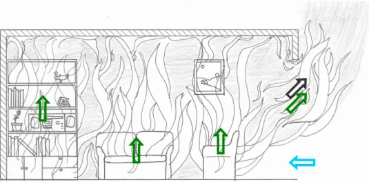
Most previous research has concentrated on scenarios where the fuel source is located close to the floor. The main mechanisms for such fires have been identified, and to a certain degree predictions of the growth of a fire and the resulting temperatures in the compartment are possible [Karlsson and Quintiere 2000]. The basic scenarios are depicted in schematic fashion in Fig. 1.1.
If a fuel source is located in a compartment, then heat, smoke and hot gases will be trapped and the air supply will be restricted. If the compartment is extremely well ventilated, then the effect may be small, and the fire may grow in more or less an identical way to how it would if it were in the open [Drysdale 1998]. This case is depicted in Fig. 1.1a. More
Fig. 1.1: Schematic illustration of the main behaviour types which can be encountered when a fire is in a compartment.
restricted, but still quite large ventilation, will lead to the buildup of a substantial layer of hot smoke and gas underneath the ceiling, as depicted in Fig. 1.1b [Drysdale 1998], [Karlsson and Quintiere 2000]. The heat feedback from this layer and from the walls and ceiling to the fuel bed will increase the rate at which the fuel is converted into its gaseous phase and released into the compartment, increasing the size of the fire.
If the ventilation is further restricted, and limited to the order of magnitude of a typical door or window, then the hot layer can grow so large as to fill practically the whole of the compartment [Drysdale 1998], [Karlsson and Quintiere 2000]. At the same time, the heat transfer to the flammable objects will be such that all flammable items in the compartment will ignite. This is shown in Fig. 1.1c.
If the vent is very small, the supply of air to the fire may be insufficient to sustain it. Under such conditions, various different patterns of behaviour have been observed, including extinction [Drysdale 1998], [Karlsson and Quintiere 2000], smouldering [Drysdale 1998], [Karlsson and Quintiere 2000], [Gross and Robertson 1965], oscillations of the combustion rate [Takeda and Akita 1981] and spontaneous fireballs [Hayasaka et al 1996].
Little research has previously been performed into fires when the fuel source is located close to the ceiling, as may for example occur when electric cables overheat or pipes transporting organic solvents rupture. Consequently, little is known about the behaviour of fire in such cases.
Such scenarios were studied at the Laboratoire de Combustion et de Détonique (LCD) as part of a project looking into questions raised by Electricité de France (EdF) and the Institut pour Radioprotéction et Sûreté Nucléaire (IRSN) regarding the risks associated with fires in installations where radioactive materials are processed [Bertin 1998], [Bertin et al 2002], [Coutin 2000], [Coutin et al 2000], [Coutin and Most 2003]. Such installations pose specific
a b c d
problems for fire safety engineers, as in many compartments the ventilation rate and pathways are controlled so as to reduce the possibility of radioactive dust escaping to the environment [Audouin et al 1997].
This earlier project at the LCD aimed among other things at discovering whether or not sustained combustion is possible when the fuel source is located in a zone filled with fuel and combustion products but to which there is no supply of air, and at describing the behaviour of the flames.
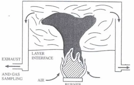
During that project configurations were studied where a gas burner was used to partially simulate the degradation of a solid fuel bed, or the evaporation of a liquid fuel. This allows the fuel flow rate to be set by the person running the experiment rather than it being determined by the heat flux to the fuel bed.
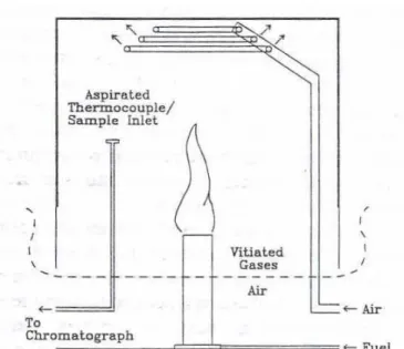
The burner was located inside a compartment fitted with a soffit to trap a layer of hot smoke and combustion products. When the burner is located low in the compartment, a diffusion flame and smoke plume will form above it. When the burner is located close to the interface between the layer of smoke and the air layer below it, flames may appear at the layer interface. These two scenarios are depicted in Fig. 1.2 a and b. Much of the work concentrated on cases when the burner is located inside the upper layer. Under such circumstances, at low fuel flow rates the flame will extinguish; at higher fuel flow rates, the behaviour depicted in
Fig. 1.2c will occur: the flame will detach itself from the burner and stabilise itself at the layer interface.
Fig. 1.2: Behaviour patterns observed when a gas burner is placed in a compartment.
The current project was initiated to describe in more detail the phenomena observed by Coutin [Coutin 2000], [Coutin et al 2000], [Coutin and Most 2003] during the earlier project. It was performed within the FIRENET research network, an international network funded by the European Union (EU) to study various aspects of compartment fires. A central object of study were blue flames which occur in a configuration as depicted in Fig. 1.2c when the fuel
a b c d
flow rate is just above the minimum necessary to sustain combustion. Furthermore, work was performed to study the behaviour when the size of the vent is reduced, as suggested in Fig.
1.2d.
1.2 Literature Review
In order to understand the behaviour of fires with the fuel source close to the ceiling, it is necessary to first understand the combustion process in general and the behaviour of the more usual compartment fires where the fuel source is near the floor. This section therefore starts with an introduction of the combustion process and of the key mechanisms involved in fires when the fuel source is in the open, then presents the behaviour regimes of compartment fires when the fuel source is close to the floor, before exploring the behaviour associated with fires where the fuel source is raised above the floor.
1.2.1 The Combustion Process
There are two basic types of flame: premixed and diffusion [Drysdale 1998]. The flames encountered in compartment fires are mostly diffusion flames, but some of the concepts of premixed burning are required in the discussion of several aspects of fires, notably ignition and extinction.
Flaming combustion is a phenomenon which involves materials in their gaseous phase. Therefore, prior to flaming a condensed fuel (i.e. solid or liquid) is converted into vapour and gas through pyrolysis, sublimation and/or evaporation. This conversion is driven by the flux of heat to the surface of the solid or liquid. In simplified terms, the rate of production of vapour per surface area of the solid or liquid pool m&F′′ (also known as the “burning rate”) is determined by the heat flux from the flame and from any external heat source, and a “latent heat of gasification” [Drysdale 1998]
L loss ext fl F q Q Q Q m′′ = ′′ + ′′ − ′′ & & & & ( 1.1 )
Fig. 1.3: Illustration of the energy flows involved in the degradation of a solid or liquid fuel
whereQ&fl′′is the heat flux from the flame to the surface, Q&ext′′ the heat flux from external sources
to the surface, Q&loss′′ the heat losses and qL the necessary heat per mass of the fuel for the conversion to the gaseous phase. The fire will grow if the net heat flux to the solid is greater than that required to produce the amount of fuel vapour needed to sustainQ&fl′′.
The mass flow of gaseous fuel transports a flow of chemical energyH& which equates to
c F h m ∆ = & & H ( 1.2 )
where ∆hc is the heat of combustion per mass of the fuel.
The combustion reaction itself can be described in idealised form with the equation
→ + + 2 2 y x N 21 79 O H C 2 2 y xH O O C N N N
(
)
2 2 N2 21 79 O H 2 CO 2 y x y xH C H O C N N y N x + + ⋅ ( 1.3 )with the quantities of fuel and oxygen being in stoichiometric proportions
4 1 y x N N 2 y x O H C + = ( 1.4 ).
where Ni is the number of moles of each species. The stoichiometric fuel-to-air ratio is more
usually expressed in terms of mass rather than moles:
r m m m y x N O H C = + ( 1.5 ) fl Q& ext Q& loss Q& F m&
or, combined with ( 1.4 ) + + = + = 2 2 y 2 2 2 2 y x y x N O H C N N O O H C H C M M y x M M N M N M N r 21 79 4 2 ( 1.6 )
where Miis the molar mass of the species i.
It will not necessarily be the case – indeed particularly with fuels with large molecules it is rarely the case in practice – that all the gaseous fuel is combusted [Drysdale 1998]. Most fires will emit quantities of unburned and partially burned fuel in the form of gases, vapours and aerosols.
The rate of conversion of chemical energy to heat, or “heat release rate” (HRR) Q&prod, can be considered as being equal to the flow rate of chemical energy multiplied by an efficiency factor, the “combustion efficiency” ηc
H& &
c prod
Q =η ( 1.7 )
The HRR depends not only on the material involved and the size of the solid object, but also on its geometry, on the arrangement if the solid comprises several different materials, and on the environment. Prediction based purely on theoretical foundations is therefore in practice almost impossible for anything more than the most simple of configurations, and so normally measurements are required [Drysdale 1998], [Karlsson and Quintiere 2000].
A key factor in any combustion process is the ratio of available oxidant and fuel. This ratio directly affects the chemical reaction in the case of premixed flames, but also in the case of diffusion flames the combustion efficiency is influenced by this ratio.
These ratios are normally expressed in the form of “equivalence ratios” [Drysdale 1998],
the ratio between the fuel to air ratio and the stoichiometric ratio r:
r m m A F & & = ϕ ( 1.8 ).
1.2.2 Fires in the Open
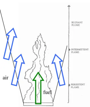
Fire Plumes
Above the solid body of fuel, gaseous fuel will rise upwards, mixing with air to form a plume and burning in a diffusion flame [Karlsson and Quintiere 2000].
The plume comprises three parts as illustrated in Erreur ! Source du renvoi introuvable.
[Drysdale 1998]: the zone between the height of the fuel bed and the height at which flame is always present, the zone corresponding to the range of heights at which there is an intermittent presence of the flame, and the zone above the height of the furthest reach of the flame tips.
The rate of entrainment of air into the plume will determine the volume and temperature of the resulting smoke and gas.
Several models exist to predict the amount of air entrained into a plume, although none provide a simple, accurate, universal, closed-form formula. Karlsson and Quintiere present a range of models in their textbook [Karlsson and Quintiere 2000].
The rate of entrainment is normally sufficiently high that the amount of air required for combustion of the fuel will have been entrained after only a short distance equating to a fraction of the height of the flames.
Flame Length
If the flames from different fuel sources are to be compared, it is not sufficient for the energy release rates to be compared – also the heights of the flames must be looked at (see Section 2.2.1) [Drysdale 1998], [Karlsson and Quintiere 2000]. In addition, the comparison of heights of flames and of compartment ceilings is of importance if a fire is in an enclosure.
In order to quantify the height, most authors define the height of the flame Hfl as the height beyond which the flame tips reach for half the duration of the observation [Drysdale 1998], [Karlsson and Quintiere 2000].
The flame height is primarily determined by the ratio between the initial inertia and the buoyancy of the fuel. This ratio can be expressed through the Froude number Fr or the
“nondimensional energy release rate” Q* gD v Fr initiial 2 = ( 1.9 )
where vinitial is the velocity of the gaseous fuel when it leaves the orifice of the burner, pool or solid surface, and D is the diameter of the burner/pool/solid [Karlsson and Quintiere, 2000]. An alternative expression used by many authors is the “nondimensional energy release rate”
5 . 2 * D g T c Q Q p ∞ ∞ ρ = & ( 1.10 )
where Q& is the heat produced by the combustion and ρ∞, cp and T∞ are the density, specific
thermal capacity and temperature of the ambient air. The correlation between the two can be illustrated if the velocity in the Froude number is expressed in terms of the fuel flow rate and burner geometry – see [Karlsson and Quintiere, 2000]. Low values of Fr or Q* (Fr < 10-5 or Q* a 1) correspond to pool fires and fires of solids, where the initial velocity is low. High values (Fr > 107 or Q* > 106 correspond to fires of gas jets.
Fig. 1.4: Schematic of a fire plume
adapted from [Drysdale 1998]
Fig. 1.5: Experimentally determined correlation between the “nondimensional energy release rate” Q* and the flame length Hfl.
Source: [Karlsson and Quintiere 2000]
air
fuel
Fig. 1.5 shows the correlation, determined from several experimental studies, between
Hfl, and the heat release rate, expressed in terms of Q* [Karlsson and Quintiere, 2000]. The data are well correlated with Q*, although to describe the resulting link between the two, separate mathematical formulae are required for different ranges of Q* – see [Drysdale 1998].
Orloff and De Ris [1982] measured flame heights during tests with burner diameters D ranging from 0.1 m to 0.7 m and energy flow rates H& ranging between 25 and 250 kW. From
their data, they suggested the correlation
2 m MW 4 2 . 1 3 D Hfl π ⋅ ≈ H& ( 1.11a )
or in other words the ratio between the energy flow rate H& and the volume of flame Vfl is
constant 3 m MW 2 . 1 ≈ fl V H& ( 1.11b ). Within the range of fuel flow rates and burner sizes within that study, this simplified formula would seem to be a reasonable approximation [Drysdale 1998].
1.2.3
Compartment Fires
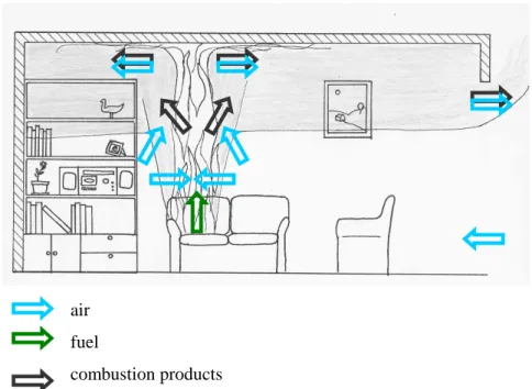
If a fuel source is placed inside an enclosure, the plume gases and heat will be trapped underneath the ceiling and the air flow to the fire will be restricted. This can lead to the behaviour of the fire being changed substantially, for example through an increase in the amount of heat transferred to the fuel source [Drysdale 1998], [Karlsson and Quintiere 2000]. Often this will increase the rate at which the fire grows and the maximum heat release rate obtained.
1.2.3.1 Fires in Very Well Ventilated Compartments
A compartment fire will usually start with the ignition of a single object in the compartment. The fire will initially grow in a similar fashion to a fire in the open, with the fire
gradually spreading over the object. Smoke, hot gas and flames will rise upwards in a plume and then travel underneath the ceiling and out through the upper part of the vent, while fresh air is entrained in through the lower part of the vent [Drysdale 1998], [Karlsson and Quintiere 2000].
As the passage of hot smoke and gas is at least partially restricted, a hot layer will form underneath the ceiling. The burning object will be subject to heat flux not only from the plume, but also from the layer of smoke and gas and from the ceiling and walls. In accordance with equation ( 1.1 ), this extra heat flux will increase the pyrolysis rate, and consequently the rate will normally be greater than if the burning object were in the open.
As the combustion rate is primarily by the type and size of the fuel source, such behaviour is known as “fuel-control”.
Fig. 1.6: Schematic of the mass flow in a fuel-controlled fire air
fuel
combustion products
1.2.3.2 Fires in Compartments with “Normal” Ventilation
If the ventilation to a compartment is limited to one or two doors or windows, then the buildup of smoke and hot gas underneath the ceiling will typically be so great that the behaviour of the fire will be significantly changed.
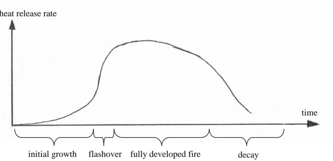
If left to run its course without any changes to the ventilation or attempts to extinguish it, such a fire will normally pass through a series of phases during its development [Drysdale 1998], [Karlsson and Quintiere 2000].
Fig. 1.7: Schematic illustration of the development of the heat release rate over time for a “typical” compartment fire.
1.2.3.2.1
Initial Growth
In most cases, a fire will start with the ignition of a single item of fuel. Initially it will behave much in the same way as described for fires in very well ventilated compartments, and in particular be fuel-controlled [Drysdale 1998], [Karlsson and Quintiere 2000]. The fire will gradually spread over the combustible item and possibly spread to adjacent items, increasing the buildup of the hot layer beneath the ceiling.
time heat release rate
initial growth flashover fully developed fire decay