HAL Id: tel-01486773
https://tel.archives-ouvertes.fr/tel-01486773
Submitted on 16 Mar 2017
HAL is a multi-disciplinary open access archive for the deposit and dissemination of sci-entific research documents, whether they are pub-lished or not. The documents may come from teaching and research institutions in France or abroad, or from public or private research centers.
L’archive ouverte pluridisciplinaire HAL, est destinée au dépôt et à la diffusion de documents scientifiques de niveau recherche, publiés ou non, émanant des établissements d’enseignement et de recherche français ou étrangers, des laboratoires publics ou privés.
switchable façade elements
Thibault Pflug
To cite this version:
Thibault Pflug. Development, characterization and evaluation of switchable façade elements. Eco-conception. Université de Strasbourg, 2016. English. �NNT : 2016STRAD017�. �tel-01486773�
UNIVERSITÉ DE
STRASBOURG
ÉCOLE DOCTORALE MSII
Laboratoire ICube, département mécanique
THÈSE
présentée par :Thibault PFLUG
Soutenance prévue le : 06 Juillet 2016
Pour obtenir le grade de : Docteur de l’université de Strasbourg Discipline/ Spécialité
: ÉNERGÉTIQUE
Développement, Caractérisation et
Évaluation d’Éléments de Façades
Commutables
-
Development, Characterization and
Evaluation of switchable façade
elements
THÈSE dirigée par :SIROUX Monica Professeur, Laboratoire ICUBE, INSA Strasbourg
RAPPORTEURS :
SALAGNAC Patrick Professeur, Laboratoire LASIE, Université la Rochelle LASSUE Stéphane Professeur, Laboratoire LGCGE, Université d'Artois
AUTRES MEMBRES DU JURY :
KUHN Tilmann Docteur, Institut Fraunhofer ISE, Freiburg MAURER Christoph Docteur, Institut Fraunhofer ISE, Freiburg MARCHIO Dominique Professeur, CES, Mines ParisTech
Table of contents
Table of contents ... 3 Acknowledgements ... 5 Abstract ... 6 English version ... 6 French version ... 6 German version ... 7 Nomenclature ... 9 1 Introduction ... 11 1.1 Context ... 11 1.2 Problem statement ... 141.3 Existing solutions: state of the art ... 17
1.4 Performance indicators ... 23
2 Closed movable insulation system ... 25
2.1 Introduction ... 25
2.2 Case study: investigation of the switchable U-value on the building level ... 27
2.2.1 Reference: well-insulated office room ... 27
2.2.2 Variants with switchable U-value ... 28
2.2.3 Results and discussion ... 32
2.3 Experimental study: investigation on the component and material level ... 36
2.3.1 Optical characterization of the translucent insulation material ... 36
2.3.2 U-value measurements ... 41
2.4 Detailed physical model: investigation on the component level ... 48
2.4.1 Model description ... 48
2.4.2 Validation ... 70
2.4.3 Results and discussion ... 76
2.5 Conclusion: closed movable insulation system ... 90
3 Removable insulation system ... 92
3.1 Introduction ... 92
3.2 Investigation of an individual component ... 94
3.2.1 Experimental study ... 94
3.2.2 Theoretical investigation ... 99
3.2.3 Comparison between measurement and ISO 150999 model ... 126
3.3 Evaluation of the element in a building application ... 128
3.3.1 Modeling approach ... 128
3.3.2 Results and discussion ... 140
4 Conclusion and perspectives ... 158 4.1 General conclusion ... 158 4.2 Perspectives ... 159 5 References ... 160 6 List of publications ... 168 7 Appendix ... 169 8 Résumé étendu ... 172
Acknowledgements
Thanks to Christoph Maurer, for his constant backing, availability and numerous advises! Thanks to Julie. Your love and trust brings me forward. Thanks also to my parents, parents in law, brother and sisters for their constant support.
Thanks to Bruno Bueno, for the freedom you gave me.
Thanks to Cosima Braesch, for your motivation and commitment to the task!
Thanks to Professor Monica Siroux for being a comprehensive tutor, and helping me pushing this thesis to an end.
Thanks to Tilmann Kuhn, for your efforts to allow me to do this thesis in good conditions. Thanks to Christoph Cappel. One cannot think of a better office buddy !
Thanks to Johannes Hanek for his creative mind!
Thanks to the whole Sofa team from the Fraunhofer Institut for Solar Energy Systems (ISE), working with you was a great experience.
The author wants to thank Mr. Sergej Kvasnin for his great ideas and enthusiasm !
Part of this work was funded by the BMWi (Germany ministry of economic affairs) under the auspices of grant 03ET1032B (Integriertes Wärmemanagement-Fassadenelement (WaMaFat)) which is part of the EnOB (Forschung für Energieoptimiertes Bauen) initiative.
The author wants to thank Nikolas Nestle for being an impressive and honest project leader. Thanks to all the team of the Wamafat project for the great work and the productive project meetings.
The work presented in this thesis was partially done in cooperation with the company of Mr. Sergej Kvasnin, the I[n]solation UG (haftungsbeschränkte Unternehmergesellschaft, Waldecker Strasse 5B, 33647 Bielefeld, Germany). This cooperation has been financed by the foundation Rud. Otto Meyer-Umwelt-Stiftung.
Part of the research leading to these results has received funding from the European Community’s Seventh Framework Program (FP7/2007-2013) under grant agreement n°314461.
Abstract
English version
The new building energy regulations in Europe imply always better insulated building facades. The increase of the building insulation level reduces significantly the heating energy demand of buildings. However, it can also increase prevent the building to cool down during the cooling period, when the external conditions are favorable, which can create additional cooling loads and overheating in summer. In this thesis, the concept of façade elements with switchable thermal properties, or switchable insulation, is developed. Switchable insulations are insulation systems that can be deactivated whenever it is of advantage considering the external conditions. The overall heat transfer coefficient of the façade, the U-value, can then be switched from a low, insulating value, to a high, heat conducting value: during the cooling period, this can be used to cool down the building’s mass during the night or colder periods. During the heating period, the switchable insulation can be used to whenever it is warm outside and solar gains can be used. In this thesis the potential of switchable insulation for an European continental climate and for office buildings is investigated. Also, two new concepts of switchable insulation are introduced and developed. The new façade elements are characterized experimentally, with numerous U-value and optical properties measurements. For the first technology, a detailed thermal nodal model has been introduced, validated and used to assess the impact of relevant parameters on the performance of the new façade element. The second new façade element has been investigated from individual forms of heat transfer on the level of an air cavity to the level of a whole façade element. A prototype has been tested experimentally. The potential of switchable insulation in general and the two new elements in particular is investigated on a building level, using building energy simulation. Several control strategies have been developed, introduced and compared. The influence of thermal mass on the reduction of heating and cooling demand was also investigated, as well as the influence of the orientation or the elements’ frame. It was shown that the heating and cooling demand can be reduced by up to 30 % by using switchable insulations.
Keywords: switchable insulation, heat transfer, façade elements, building heating and cooling energy demand, experimental investigation, U-value, physical model, thermal model, optical model, potential analysis, thermal mass, comfort.
French version
Les nouvelles réglementations énergétiques en Europe impliquent des façades de bâtiments mieux isolées. L'augmentation du niveau d'isolation des bâtiments permet de réduire considérablement les besoins de chauffage. Cependant, ces résistances thermiques importantes des parois peuvent aussi diminuer le refroidissement du bâtiment en été,
quand les conditions extérieures sont favorables. Ceci peut créer des charges de refroidissement supplémentaires et cause des surchauffes en été. Dans cette thèse, le concept d’éléments de façade à propriétés thermiques commutables, ou isolations commutable, est développé. Les isolations commutables sont des systèmes d'isolation qui peuvent être désactivés à chaque fois qu'il est possible de profiter des conditions extérieures pour diminuer les besoins de refroidissement ou de chauffage du bâtiment. Le coefficient de transmission thermique de la façade U peut alors être commuté d'une faible valeur (état isolant) à valeur élevée (état conducteur): pendant les périodes de refroidissement, cela peut être utilisé pour refroidir la masse du bâtiment pendant la nuit ou quand il fait plus froid à l’extérieur qu’à l’intérieur. Pendant les périodes de chauffage, ce concept peut être utilisé à chaque fois qu'il que les températures extérieures sont assez chaudes ou que les gains solaires peuvent être utilisés. Dans cette thèse, le potentiel des isolations commutables pour un climat continental européen est étudié. En outre, deux nouveaux concepts d'isolations commutables sont introduits et développés. Les nouveaux éléments de façade sont caractérisés expérimentalement, avec de nombreuses mesures de la valeur de U ainsi que des mesures des propriétés optiques. Pour la première technologie présentée, un modèle nodal détaillé a été mis en place, validé et utilisé pour évaluer l'impact des paramètres les plus pertinents sur la performance énergétique du nouvel élément de façade. Le second nouvel élément de façade a été étudiée en allant des transferts de chaleurs dans une cavité d’air jusqu’à l’élément de façade dans son ensemble. Un prototype a été testé expérimentalement. Le potentiel des isolations commutables en général et des deux nouveaux éléments en particulier a été étudié au niveau en utilisant la simulation énergétique dynamique du bâtiment. Plusieurs stratégies de contrôle ont été mises au point, introduites et comparées. L'influence de la masse thermique sur les réductions des besoins de chauffage et refroidissement a également été étudiée, ainsi que l'influence de l'orientation ou du cadre des éléments. Il a été montré que les besoins de chauffage et de refroidissement être réduits jusqu'à 30 % grâce aux isolations commutables.
Mots-clés: isolation commutable, transfert de chaleur, éléments de façade, réduction des besoins de chauffage et refroidissement, étude expérimentale, coefficient de transmission thermique U, modèle thermique et optique, analyse de potentiel, influence de l’inertie thermique, confort.
German version
Die neuen Gebäuderegelungen in Europa führen zu immer besser isolierten Gebäudehüllen. Die Erhöhung der Gebäudedämmung reduziert deutlich den Heizenergiebedarf während der Heizperiode deutlich. Durch die erhöhte Isolierung der Gebäudehülle kann aber auch die nächtliche Abkühlung des Gebäudes während der Kühlperiode vermindert werden wenn die äußeren Bedingungen günstig sind, was zusätzliche Kühllasten verursachen kann sowie eventuelle Überhitzungszeiten im Sommer. In dieser Arbeit wird das Konzept von
Fassadenelementen mit schaltbaren thermischen Eigenschaften -oder schaltbare Isolierung- entwickelt. Schaltbare Isolierungen sind Dämmsysteme, die deaktiviert werden können wenn es von Vorteil ist. Der Wärmedurchgangskoeffizient der Fassade (U-Wert) schaltet dabei von einem niedrigen zu einem hohen Wert (wärmeleitender Zustand): in der Kühlperiode kann dann die Gebäudemasse zum Beispiel in der Nacht durch die Außentemperatur gekühlt werden. In der Heizperiode kann die Isolierung deaktiviert werden um zu Beispiel solaren Gewinne zu sammeln. In dieser Arbeit wird das Potential von zwei innovativen schaltbaren Isolierungen für ein europäisches Kontinentalklima und für Bürogebäude untersucht. Die beiden Ideen werden vorgestellt und verschiedene Varianten werden entwickelt. Diese neuen Fassadenelemente werden experimentell charakterisiert mit zahlreichen U-Wert Messungen sowie Messungen der optischen Eigenschaften. Für die erste Technologie wird ein detailliertes thermisches Knotenmodell entwickelt, validiert und verwendet um den Einfluss der Gestaltungsparameter auf die Leistung des neuen Fassadenelements zu quantifizieren. Die zweite Technologie wird von der Ebene der Wärmetransporte in einer einzelne Kavität bis zur Untersuchung der Leistung von den gesamten Fassadenelementen analysiert. Das Potential von schaltbarer Isolierung im Allgemeinen und von den beiden neuen Elementen insbesondere wird auf Gebäudeebene untersucht anhand von Gebäudeenergiesimulation. Mehrere Steuerungsstrategien wurden entwickelt, eingeführt und verglichen. Der Einfluss der thermischen Masse auf die Einsparung wurde auch untersucht, sowie den Einfluss der Fassadenausrichtung oder des Rahmens der Elemente. Dabei konnte gezeigt werden, dass sich der Heiz- und Kühlbedarf durch jede Technologie um bis zu 30 % reduzieren lässt.
Stichwörter: schaltbare Isolierung, Wärmeübertragung, Fassadenelemente, Heiz- und Kühlbedarf, Nachtkühlung, Messung, physikalisches Modell, physikalisches Modell, optisches Modell, Potenzialanalyse, thermische Masse, Komfort.
Nomenclature
Thermal and airflow properties and variables:
α [m2*s-1] the thermal diffusivity of a fluid.
Ar [-] the aspect ratio of a duct.
β [K-1] the thermal expansion coefficient of a fluid.
Cp [J*kg-1*K-1] the specific heat of a fluid.
Dh [m] the hydraulic diameter.
ΔP [Pa] a pressure drop.
ΔT [K] a temperature difference.
ε [-] the longwave emissivity of a surface.
ζ [-] a drag coefficient.
g [-] the center-of-glazing solar heat gain coefficient.
h [W*m-2*K-1] a heat transfer coefficient.
H [m] a height.
I [W*m-2] the solar irradiance incoming at the façade.
J [W*m-2] the longwave radiosity.
λ [W*m-1*K-1] the thermal conductivity of a fluid or solid.
L [m] the length of a duct or air gap in the direction of the airflow. 𝑚̇ [kg*s-1] the mass flow rate in a duct.
ν [m2*s-1] the kinematic viscosity.
qint [W*m-2] the heat flux from the façade’s internal surface to the interior through convection, conduction and longwave radiation.
ρ [kg*m-3] the mass density of a fluid.
Tx [K] a surface (x=surf), exterior (x=ext), interior (x=int or room) or gas (x=gas) temperature.
U or Ug [W*m-2*K-1] the center-of-glazing U-value or overall heat transfer coefficient of a façade system.
Uf [W*m-2*K-1] the U-value of the frame of a façade system.
v [m*s-1] a velocity.
Optical properties and variables:
αx [-] the absorptance of a material or layer in the visible (x=vis) or solar (x=sol) spectral range.
ρx [-] the reflectance of a material, layer or system in the visible (x=vis) or solar (x=sol) spectral range. The reflectance can be normal-hemispherical (x=n-h), direct-hemispherical (x=dir-h=d-h) or hemispherical-hemispherical (x=h-h).
τx [-] the transmittance of a material, layer or system in the visible (x=vis) or solar (x=sol) spectral range. The transmittance can be normal-hemispherical (x=n-h), direct-hemispherical (x=dir-h=d-h) or hemispherical-hemispherical (x=h-h).
Dimensionless numbers:
Gr [-] the Grashof number.
Nu [-] the Nusselt number.
Pr [-] the Prandtl number.
Ra [-] the Rayleigh number.
Re [-] the Reynolds number.
Abbreviations:
IR Infrared
dir, dif Respectively direct and diffuse radiation
1
Introduction
1.1 Context
In 2010, the European Union defined its 2020 goals on the energy performance of buildings in the recast European Energy Performance in Buildings Directive (EPBD) (European Parliament 2010), since the building sector accounted for 40 % of the total energy consumption in the Union: in order to decrease energy dependency and reduce greenhouse effects, the European Union gave ambitious goals for 2020, one of them being that all new buildings have to be nearly zero energy buildings by 31 December 2020 (public buildings by 31 December 2018). Also, on the national levels, new and more restrictive building energy performance regulations appeared in the last decade, such as the Energieeinsparverordnung (EnEV 2009) in Germany (actualized in 2014) or the Réglementation Thermique 2012 (RT2012) in France. More challenging labels for the energy performance of buildings exists, such as the PassivHaus (Passivhaus Institut 2015) or Minergie (Verein MINERGIE 2014) labels. This regulations and labels have always more constraining targets for the building energy demand, with for example the Réglementation Thermique 2012 requiring for example a maximum of 50 kWh*m-2*yr-1 of primary energy demand for heating, cooling, artificial lighting, warm water, pumps and fan (slightly variable depending on location, etc.). The PassivHaus regulation implies that the total annual primary energy consumption (heating, cooling hot water and electricity) must not exceed 120 kWh*m-2, and an annual heating demand limit of 15 kWh*m-2 in heating and cooling energy, or a maximum heat load of 10 W*m-2 (PassivHaus Institute 2015). Often, this regulation also give an upper limit for the U-value of insulated opaque walls, such as 0.15 W*m-2*K-1 for the PassivHaus label (PassivHaus Institute 2015). The Italian legislative decree No. 311/2006 also aims at maximum reduction in wintertime heat losses and consequently important thermal insulation (Stazi et al. 2009).
The traditional and obvious way to decrease the building heating energy demand is to insulate the surfaces in contact with the exterior. The decrease of this maximum building energy demand allowed by regulations as well as the increasing price of energy implied an increase of the overall insulation thickness and the development of insulation materials. The goal is to minimize conduction, convection and longwave radiation within the material, illustrated by Figure 1 (Kuhn 2015):
Figure 1 – The different ways of heat transport in building materials: Convection within the gas gaps, thermal conduction via the solid skeleton/solid pore walls (bold black arrow) or the filling gases (small arrows) and thermal radiation heat transfer between the pore walls and through the
pore walls in case of IR-transparent materials (curved arrows). These heat transport phenomena are detailed more in section 3.2.2.1.1. Source: (Kuhn 2015).
Traditional insulation materials such as expanded polystyrene (EPS) and extruded polystyrene (XPS) are closed-cell material that use trapped air as the insulating medium, avoiding convection due to the small sizes of the cells. The thermal conductivity of such material is typically between 0.031 W*m-1*K-1 and 0.040 W*m-1*K-1. Neopor® (BASF 2016) is a further development of XPS where longwave radiation exchange has been minimized by the use of graphite, reducing the longwave transmittance of the cells’ walls and thus reaching a thermal conductivity of about 0.031 W*m-1*K-1. By using gases with a lower thermal conductivity than air, Polyurethane (PUR) has values typically ranging from 0.020 to 0.030 W*m-1*K-1 (Jelle et al. 2010). Innovative products have been developed recently, a good review of them having been done in (Jelle et al. 2010) and (Jelle 2011): vacuum insulation reaches for example conductivities around 0.004 W*m-1*K-1 in fresh condition, but could increase to 0.008 W*m-1*K-1 after 25 years of use, due to water vapor and air diffusion through the VIP envelope and into the VIP core material which has an open pore structure (Baetens et al. 2010; Jelle 2011). Also, VIP cannot be adjusted by cutting at the building site nor perforated. Gas filled panels (for example with Argon) don’t need to be maintained at such a low pressure, but the thermal conductivity is similar to conventional
Heat transport in building materials and components
radiative heat transfer Convective heat transport in gas gas-filled nano pore conductive heat transport in solid states
insulation. Aerogel technologies are also very promising, with commercially available aerogels reaching conductivities down to 0.013 W*m-1*K-1: in (Gao et al. 2016), payback times of less than 10 years were calculated compared to a reference with a double glazing unit and assuming an aerogel cost of 4000 EUR*m-3. Nanomaterials in general (including aerogels) could achieve thermal conductivities below 0.004 W*m-1*K-1: when the pore diameter in the material is decreased below a certain value (40 nm if the gas contained in it is air), the overall thermal conductivity becomes very low: when the mean free path of the gas molecules is larger than the pore diameter, a gas molecule inside a pore is more likely to hit the pore wall than another gas molecule, thus reducing the conduction of heat in the gas. This is known as the Knudsen effect.
Insulation materials and systems are reaching very low thermal conductivities, and insulated facades tend toward really low U-values. Thus, the unwanted heat flux to or from the exterior environment can be avoided. The importance of thermal insulation for the reduction of heat loss in winter is not to be proven anymore. The improvement of the building shell of existing and new residential buildings offers a huge potential for energy savings in the next decades in Europe, as was shown in (Lechtenböhmer und Schüring 2011), providing a country-by-country bottom up simulation of residential buildings for the whole EU and using strong assumptions. Thermal insulation also offers low payback time (Nyers et al. 2015). Conventional internal and external insulation system also proved their durability over time from the thermal–hygrometric and mechanical point of view (Stazi et al. 2009). However, a building envelope with a very low and constant overall U value also reduces beneficial heat fluxes from or to the exterior, which could lead to overheating and discomfort in the building. In the next chapter, these limitations are detailed, leading to the problem statement.
1.2 Problem statement
A high level of insulation can lead to increased cooling load and overheating risks. (Berger et al. 2016) shows for example that with additional insulation in place, the cooling demand in summer increases as it tends to slow down nocturnal cooling processes. In (McLeod et al. 2013), the author summarizes studies on the overheating risks in passive house buildings:
- the occupants of passive house dwellings often report better thermal comfort in winter than in summer, quoting for example (Mlecnik et al. 2012) and . (Berndgen-Kaiser 2010).
McLeod give numerous example of northern passive houses showing overheating, for example the study of (Larsen und Jensen 2011): for the Danish passive house dwellings considered in this study, the indoor dry bulb temperature exceeded 26°C 40 % of the time during July 2009 and 60 % of the time in 2010, resulting in “severe overheating”. One interesting fact is that this overheating was not predicted by the PHPP (Passive House planning package) model of the certified dwellings, but could afterwards be replicated with a dynamic simulation program.
The risk of overheating in these well insulated buildings is highly dependent upon: - Solar transmission.
- Internal heat gains due to occupancy, light, computers and other auxiliary equipment.
- The presence of a shading device. - The glazing to wall ratio.
- The orientation of the glazed areas.
- Thermal mass, which plays a clear role in reducing the overall duration of overheating in the passive house.
Of course, not all well insulated building lead to high overheating in summer: McLeod gives also some examples of studies resulting in high levels of occupant satisfaction under summer conditions, with for example results from Schnieders (Jürgen Schnieders und Andreas Hermelink 2006).
In (Feist et al. 2005), measurement results of passive houses in Kronberg (Germany) are presented: for the house analyzed during a hot summer week (outdoor air temperatures up to 34.5°C), it is stated that “there is nothing to feel inside the house from the very strong diurnal variation of the outside air temperature”. However, an augmentation of the room air temperatures in the upper floor from 24.3°C to 27.1°C is observed, and the inner air temperatures for both floors almost never fall below 24°C, also during nighttime.
Based on these previous results, it is clear that the risk of overheating and cooling load peaks in well insulated dwellings exists. Numerous solutions exist to reduce this risk as well
as the cooling loads, as for example shading devices such as e.g. external blinds external blinds (Kuhn 2006b) or glazing solutions with reduced g-values (Wilson 2006). Ventilation and free cooling is also a traditional way to reduce the cooling loads. As soon as external air is led into the building, the issues of filtering, pollution, allergies, etc. must be dealt with. Also, mechanical ventilation can lead to substantial additional consumption of electricity to drive the ventilation fan. Opening windows can be effective but can issue a security problem. Also, reducing the internal heat gains can be a simple solution if possible.
In this thesis and additional way to diminish cooling loads and improve summer comfort in well insulated buildings is presented: façade elements with switchable insulation properties, also called switchable insulation. The aim is to be able to reduce the thermal resistances of the façade element during summer time when it is cooler outside, in order to:
- Accelerate the cooling of the building’s mass and so reduce the cooling load.
- Diminish the internal surface temperature of the façade, improving the radiant temperature and so the comfort of the occupants.
Also, depending on the climate, a lower thermal resistance towards the exterior can be of advantage during the heating period to profit from warm exterior temperature or solar irradiances. For the European continental climate, this can be the case during sunny winter days.
The following problem statement is investigated by this thesis: can façade elements with switchable thermal resistance reduce the energy demand (heating, cooling, artificial lighting) of a building significantly?
Additionally, how can the effect of a facade with switchable thermal resistance be quantified? How can numerous variants of such a facade be easily compared?
The author does not only want to analyze the general theoretical potential of these elements, but also to contribute to the development of two new components with switchable insulation properties.
While in this section, the examples found in the literature were somehow centered on passive house buildings due to the abundance of available literature, the results of this study will not be limited to passive houses, but to well-insulated building in general.
The study is focused on but not limited to office buildings. Office buildings are interesting targets for switchable insulations since they have high internal heat gains and large window area, leading to important cooling loads, but residential building will also be discussed. Concerning the climate, the focus is first given to the European continental climates as defined in (Kuhn et al. 2014), with cold temperatures in winter but also warm summers, average annual solar irradiance levels and important day/night variations during the year.
Within this thesis, the term “switchable” refers in priority to the thermal resistance, but could also refer to the solar heat gain coefficient as a by-product.
To present the building energy simulation results, useful energy demand is used. Useful energy is the portion of final energy which is actually available in the building (for example heat produced by a radiator) after final conversion. Compared to primary energy, useful energy is free from primary energy factors (that can vary from one country or standard to another) or energy conversion coefficients.
The work is structured as follow:
- First, the state of the art of existing switchable insulation solutions is reviewed. - Then, in chapter 2, a new switchable insulation façade system is presented. First, the
potential of this new element is investigated on a building level. Second, the technology is characterized experimentally regarding the optical and thermal properties. For the thermal properties, different geometrical and thermophysical variants are measured. The insulation material is also characterized optically. Then, a detailed physical model is introduced and validated to allow a parametric analysis of the new element.
- In chapter 3, a second innovative switchable insulation is introduced: the new facade element is then investigated at different scale, going from one cavity through the definition of the whole façade element to the building simulation. A prototype is also characterized experimentally, as are the longwave properties of the used film material.
- Chapter 4 summarizes the conclusions and findings as well as the main answers to the problem statement and perspectives.
- Chapter 5 gathers the bibliography.
- Chapter 6 presents the list of the author’s publications.
- Chapter 7 under the form of Annexes contains results that were not absolutely necessary to achieve the goals but still interesting from a scientific point of view. - Chapter 8 is an extended French summary.
1.3 Existing solutions: state of the art
In this paragraph, an overview of existing technologies of switchable insulation is presented.
One way to switch the U-value is to change the gas pressure inside a vacuum insulation panel, as presented for example by (Horn et al. 2000). In (Horn et al. 2000) the system, designed for solar heating purposes, is composed by an evacuated stainless steel panel which is filled with a compressible glass fiber mat. A few grams per m² of metal hydride within the panel permit the release (conducting state) and readsorption of a small amount of hydrogen gas. Electric input of less than 5 W/m² is constantly needed in the conducting state to heat the metal hydride to 400°C and release the hydrogen. The switchable panel is described in details in (Caps et al. 1996).This switchable panel is mounted in front of a massive wall. An absorber is applied on the switchable panel, with a glass pane and an air gap to limit heat losses to the exterior:
Figure 2 - Switchable thermal insulation panel with metal hydride. Source: (Horn et al. 2000). The panel is switched to the conductive state either when the difference of temperature between the absorbing surface and the rear surface is superior to a certain value, or when the global solar irradiance incoming at the surface is superior to a given value, in order to maximize the heat gain towards the interior in winter. Taking the weather data of Würzburg, Germany, using the finite-differences method and assuming constant optical properties, the author calculated the heat flux from the wall into the interior at constant temperature of 20°C and recorded it as heat gain over the heating period. The simulation
was performed with the element in front of a 17.5 cm sand-lime bricks wall. From April to September, the panel was kept in insulating state. After optimizing the air gaps thicknesses and using a selective absorber, the influence of the control strategies was investigated. For the temperature-difference based control strategies, the best performance was achieved with the conducting state as soon as Tabsorber-Trear>0, with 136 kWh*m-2. However, if ΔT>25 K is considered, the working hours drop from 1000 hours to 400 hours, while the heat gain only decrease by 9 %. Less working hours could lead to a longer lifetime. With the switching strategy based on irradiance, an identical maximum solar gain of 136 kWh*m-2 is reached, if the conductive state is switched on when the irradiance is over 50 W*m-2. Higher limits conduct to important drops in heat gains because larger intensities occur less frequently, while lower limits conduct to heat loss towards the exterior. The limitations of this technology are that 5 W/m² or electrical energy is needed to maintain the conductive state, and the important time of switching process (15 to 60 minutes considered by the author).
(Kimber et al. 2014) presents with a theoretical approach a switchable insulation that is very similar to the concept being investigated in chapter 3. The insulating state is achieved by separating a given air cavity into N smaller air cavities, separated by thin polymer membranes. The conducting state is achieving by physically collapsing the wall and removing the air: the polymer membranes are then compressed into a single layer as shown in following figure:
Figure 3 – Schematic drawing of the switchable insulation presented in (Kimber et al. 2014) with N internal air layers: (a) extended wall (insulated) and (c) collapsed wall (conductive) configurations. The corresponding resistance networks used by the author for the heat flow analysis are shown in (b) and (d) for respectively the insulated and conductive configurations. Source: (Kimber et al. 2014).
The presented concept has not been realized yet. The author points out that one of the main fabrication challenges is the actuation method of changing from insulated to
conductive states, and suggest the routing of the ductwork from the HVAC system of the building to inflate the wall for insulation and deflate for conduction purposes.
In (Leppkes und Olbrich 1987, 1988), a transparent cavity can be filled with insulating foam spheres to insulate and for shading purpose. The author advise a bulk density of 100 kg*m -3 of foam spheres with a diameter from 4 to 15 mm. An antistatic surface layer is needed on the spheres to allow the complete evacuation of the cavity. Without these antistatic surfaces, the static loads would prevent the complete evacuation. A surface treatment is needed to prevent the antistatic surface layer to lose its efficiency and darken the cavitys’ surrounding surfaces by friction. The thermal resistance and shading properties are not specified. Also, no method is given for the filling and emptying of the cavity, and it has most likely to be done manually.
The simplest way of switching insulation is the physical removing of the insulation: in (Sodha et al. 1982), the author presents a solarium which surfaces are covered during off-sunshine hours to prevent heat losses for heating purposes. The sunspace is situated at the south end of the house and is separated from the main house by a thick concrete wall, providing thermal mass. The U-value in the insulating state was assumed as 0.62 W*m-2*K -1, and one has to remark that a much lower U-value could be achieved with recent insulation. Taking a single day in January with the weather data of Colorado, U.S.A, the author simulates the thermal behavior of the greenhouse, by applying the Fourier heat conduction equation on the walls and doing an energy balance for the air node of the greenhouse. The author finds out that, if the off-sunshine hours insulation is not applied, the heat flux going from the greenhouse to the main house through the thermal mass decreases by 31 %, and so do the heating gains. Also, the thickness of the massive wall separating the greenhouse from the house’s interior had a very important influence on the heat flux to the interior of the house. The advantage of the physical removing of thermal insulation is that it allows the switching between really low U-values to very high U-values comparable to the one of a single-glazing unit. The inconvenient of the physical removing of conventional thermal insulation is that it would need an important mechanical power. Also, the removed insulation has then to be stocked, needing additional room from or next to the building.
In (Shima und Philip 2011), the thermal conductivity of magnetic nanofluids is switched from low to very high values by varying the magnetic field strength and its orientation. Magnetic nanofluids are materials that have the properties of fluid, while having magnetic-dependent properties. However, these technologies are now in an early stage and far away from building-scale applications.
Another method to switch the thermal conductivity is to use nanoporous materials for which even a smaller change in internal pressure produces an important change in the thermal conductivity (Berge et al. 2015). In (Berge et al. 2015), the author states that for materials with small pores below 100 nm, the thermal conductivity changes almost linearly
with a change in the air pressure. This includes aerogels and silica aerogels in particular. However, the thermal conductivities are switched from upper values of about 0.020 W*m -1*K-1 for 100 kPa to values to lower values between 0.005 and 0.010 W*m-1*K-1 for 1kPa. This upper value is much too low to allow significant cooling or heating of a building through such a surface. Also, no statement is given on the energy consumed by the vacuum pump to create or maintain this low pressure level. The author finally performs a yearly simulation of a well-insulated office building in Sweden with a switchable insulation, using a rough energy balance for each time step. The simulation shows an important decrease of the cooling load with the switchable insulation. However, the U-values used in both the insulating and conducting states are higher than the one achievable with the thermal conductivity measured with the nanoporous materials and variable internal pressure.
In (Stazi et al. 2012), a dynamic insulation, rear-ventilated (naturally) in summer, proved to be the best retrofitting solution for different type of buildings in Italy. The biggest benefits compared to traditional retrofitting solution were the increase in summer comforts:
Figure 4 – Dynamic rear ventilated insulation. The internal wall (reference) was a hollow wall brick masonry structure. The numbers indicate thicknesses in centimeters. Source: (Stazi et al. 2012).
Compared to the other retrofitting solutions, it was showed on the basis of dynamic simulation that the variant with rear ventilated insulation produced only 6 % discomfort hours according to the Italian version of (DIN EN 15251:2007), while the external insulation alone showed 37 % discomfort hours and the reference 33 %. The disadvantage of this solution is that the airflow rate and so the cooling rate in the open state varies strongly with wind pressure and temperature difference between massive wall and exterior air. If the wind pressure is superior at the top exit of the cavity, it could counteract the effect of buoyancy and slow down the airflow.
In following table, the precedent studies are summarized and compared:
Year Reference Concept
Low U-value [W*m-2*K -1] High U-value [W*m-2*K -1] Experimental or theoretical? Potential analysis on building level? 1982 (Sodha et al. 1982) The insulation on the walls and roof is
manually removed during nighttime. 0.62 6.02 Theoretical Yes 1987 (Leppkes und Olbrich 1987)
A cavity can be filled with insulating foam
spheres - - Theoretical No 1996 (Caps et al. 1996; Horn et al. 2000) Release and absorbtion of hydrogen gas by a metal hydride within
a panel 0.3 4.29 Both Yes 2011 (Shima und Philip 2011) The thermal conductivity of magnetic nanofluids is varied by applying a magnetic field. - - Experimental No 2012 (Stazi et al. 2012) Rear ventilated
external insulation 0.26 - Theoretical Yes
2014 (Kimber et al. 2014) Layers separating rectangular air cavities can be collapsed to form a single, conducting solid layer 0.26 3.47 Theoretical, but prototype existing No 2015 (Berge et al. 2015) Change of internal pressure in nanomaterial 0.05, assuming a 10 cm thickness 0.2, assuming a 10 cm thickness Both Yes
Table 1 – Summary of the different studies on switchable insulations. When only thermal conductivities where given, the U-value was calculated assuming external and internal boundary heat transfer coefficients of
Other systems using forced or naturally circulating fluid in the facade exist, but are not the focus of this state of the art since the switching of the thermal resistance is not the purpose of these systems, but rather a by-product: for example, breathable wall, also called dynamic insulation (Taylor et al. 1996) and (Gan 2000), are systems where the air supplied to the room has to go through external porous walls, thus preheating the supplied air. An important group is also mechanically or naturally ventilated facades (Saelens 2012; Poirazis 2008). A comprehensive review of innovative transparent and translucent solar facades, most of them being dynamic, is given in (Quesada et al. 2012). Trombe walls, ventilated or not (Ellis 2003), can be used to increase the solar gains. Building Integrated Solar Thermal (BIST) can be used to produced hot water and influence the g-value and thermal resistances of facade systems (Maurer 2012; Gil-Lopez und Gimenez-Molina 2013; Chow et al. 2010). To conclude this analysis, it can be seen that switchable insulation is not a completely new concept. However, only a very limited number of systems are ready for the market. Often, experimental data are missing and the analysis is completely done at a theoretical level, as can be seen in Table 1. Also, the potential of these facade systems or new materials has often not been analyzed on a building level. In this thesis, two new switchable insulation façade systems are introduced and investigated, from the building level to the element’s level or vice versa. The two elements are also characterized experimentally.
1.4 Performance indicators
Before introducing the new switchable elements in the next chapters, the two main performance indicators used throughout this thesis are presented in this section:
- The U-value, also called U-factor, expressed in W*m-2*K-1.
- The g-value, also called solar factor or solar heat gain coefficient (dimensionless). The U-value, also called U-factor, is the overall heat transfer coefficient that describes how well a building façade element conducts heat. It expresses the rate of heat transfer (in watts) through one square meter of façade element for 1 K temperature difference. The U-value is typically measured with a hot-box apparatus (ISO 8302:1991), and is defined as follow (ISO 15099:2003): U = 1 𝑅𝑡 = 1 1 ℎ𝑒+ ∑ 𝑅𝑖 +ℎ1 𝑖 Equation 1 With:
- Rt [m2*K*W-1] the total thermal resistance of the façade, from the interior (room) to the exterior.
- Ri [m2*K*W-1] the resistance of the façade’s subcomponents such as solid layers, air gaps, etc.
- hi [W*m-2*K-1] the internal boundary heat transfer coefficient between the internal surface of the façade element and the interior environment.
- he [W*m-2*K-1] the external boundary heat transfer coefficient between the external surface of the façade element and the exterior environment.
In this thesis, values of 7.69 W*m-2*K-1 and 25 W*m-2*K-1 are used for the characterization of the façade elements, as defined for example in (DIN EN 673:2011-04). This value of 25 W*m-2*K-1 for the exterior heat transfer coefficient is very high. In reality, the external heat transfer coefficients that accounts for convective heat transfer (due to buoyancy and/or wind) and longwave radiative heat transfer is often lower. However, this standardized boundary heat transfer coefficients allows the comparison innovative product with traditional window or wall elements, and are therefore used in this thesis. Lower external heat transfer coefficients would result in lower U-values, as the thermal resistance between the façade and the exterior is increased. The impact of lower external boundary heat transfer coefficient is investigated regularly in this thesis.
When solar radiation is considered, or when the resistances of the façade’s subcomponent cannot be added like in Equation 1, following definition is more suitable (ISO 15099:2003):
U =q𝑖𝑛𝑡(𝐼 = 0)
𝑇𝑒𝑥𝑡− 𝑇𝑖𝑛𝑡 Equation 2
With:
- qint(I=0) [W*m-2] the total heat flux from the interior glass pane towards the room by convection, conduction and longwave radiation, in the absence of solar irradiance.
- Text [K] the exterior temperature. - Tint [K] the interior temperature.
This definition is further developed in section 2.4.1.2.
The solar heat gain coefficient g is the fraction of the incident solar radiation that enters a room after passing through the building skin. An extensive description of calculation and measurement methods is given in (Kuhn 2015). The g-value is defined as follow (ISO 9050:2003):
g = τ + qi Equation 3
With:
- τ [-] the solar direct transmittance.
- qi [-] the secondary heat gain, which is the part of incoming solar energy absorbed in the layers of the façade flowing towards the interior of the building by conduction, convection, or longwave infrared radiation.
A more suitable definition for the calculation of façade elements is the following: g =τ ∗ 𝐼 + 𝑞𝑖𝑛𝑡 − 𝑞𝑖𝑛𝑡(𝐼 = 0)
𝐼 Equation 4
With:
- I [W*m-2] the total irradiance arriving at the element’s outer surface
- qint [W*m-2] the total heat flux from the interior glass pane towards the room by convection, conduction and longwave radiation, as defined in Equation 39.
- τ [-] the solar direct transmittance.
If not specified otherwise, the U- and g-values calculated within this thesis are center-of-glazing values which do not take into account the frame effects.
2
Closed movable insulation system
In this chapter, a new way to achieve a switchable insulation is presented and evaluated by simulations and experiments. First, the context as well as the concept of this new façade element is presented. Then, based on first measurement results, the potential of this development is shown on a case study. Numerous thermal and optical measurement results are then presented. Finally, a detailed model of the façade element is presented, validated and used for parametric analysis as well as optimization.
This approach can be perceived as top-down: first, the potential of the new concept is investigated on a building-scale, before going down to the element level. The advantage of the top down method is that a first estimation of the concept’s potential on building level could be done in an early stage of the project, before going down to the element level.
2.1 Introduction
The development of the 4 closed movable insulation system took place within the project Wamafat for “Integriertes Wärmemanagement-Fassadenelement” (“Integrated heat-managing façade element”), funded by the BMWi (Germany Federal Ministry for Economic Affairs and Energy) based on a decision by the German Bundestag under the contract ID 03ET1032B. The project partners are BASF, Vinylit (façade providers), LUWOGE consult and Fischer Architekten (Architects), as well as the Fraunhofer ISE. The goal of the project, which started in 2011, was to develop a façade element which could manage the heat in buildings with following goals:
- On cold days:
o Limit the heat losses
o Maximize the use of solar gains - On warm days:
o Increase Heat transport from inside to outside in comparison with the winter case.
o Control of solar gains o Heat storage
- In the general case: the possibility for active switching of the element between the different modes, depending on the boundary conditions.
During this project, the closed movable insulation system was developed. This basic idea has been filed for a patent (Nestle et al. 2015). The principle of functioning of the façade element is based on controlled convection inside a closed module containing one or several insulating panes. Basically, the element can be in two states, insulating or conducting:
Figure 5 – Translucent switchable facade element in the insulating state (left) and in the conducting state (right).The dimensions are not true to scale. Source: Fischer Architekten.
In the insulating state (left) the insulation panel is at the top. In this state, no large-scale convection around the panel is possible and the element behaves like a system with three insulating layers (two thin air layers and an insulation panel), the convective exchange at the bottom being negligible. This has been shown during the experimental analysis.
In the conducting state (right), the insulation panel is in a vertical middle position, with air gaps at the top and the bottom. In this state, large-scale spontaneous convection around the insulation panes is possible. This large-scale convection is due to the difference of density between the front and back gas column, which results in a driving pressure difference between back and front.
The translucent insulation material used for the test models was Basotect®, which is an insulation and sound absorption material developed by BASF. It is a low-density, open pore melamine foam and has a thermal conductivity at 20°C of 0.035 W/(m*K) (BASF 2014).
2.2 Case study: investigation of the switchable U-value on the building level
To assess energetic benefits achieved with the closed movable insulation system, building-scale simulations were conducted in the building simulation program TRNSYS (TRNSYS 2013). First, the simulation conditions as well as the simplified model are presented, before discussing the simulation results. The case study as well as multiple experimental results have been presented in (Pflug et al. 2015).
2.2.1 Reference: well-insulated office room
The simulation object was a single-room office in Ludwigshafen, Germany.
The office was simulated with a high insulation level, corresponding to the Passive House Standard. In a second step, variants were simulated by replacing part of the facade by our translucent element with switchable U-value.
The simulated office had following geometry:
Figure 6 – Simplified geometry of the simulated room. Source: Fischer Architekten.
The external facade is oriented 20° west. The main features of the simulated room are the following:
- All opaque walls (area A1) of the external façade are equipped with insulation, and have a resulting U-value of 0.17 W*m-2*K-1. Coldbridges are neglected in this case. - A2 and A3 are windows with the following features:
o Ug=1.2 W*m-2*K-1 o g-value=0.42. o τvis =0.71. o τsol =0.39.
o Ratio frame/window=0.3. Uframe=2.2 W*m-2*K-1.
The ventilation is equipped with heat recovery (details can be seen in the Appendix).Other simulation conditions are described in the Appendix.
2.2.2 Variants with switchable U-value
Considering the well-insulated reference case, variants were simulated with the new translucent Facade Element with switchable U-value): the upper part of the existing window (starting at 2.2 m from the floor) was replaced by the new translucent element (Area A3 in Figure 6). This represents 4.9 m² and 26.7 % of the external façade. While this part of the façade is only of minor relevance for visual contact to the outside environment, it is highly relevant for the supply of daylight. Scattering elements are advantageous here in the upper part of the facade as they increase light distribution deep into the room.
The solar energy directly transmitted through the façade element was directly calculated as a constant value equals to τsol*I, with I (W*m-2) being the solar irradiance incoming at the façade and τSol the transmittance in the solar range with a value of 0.05. This constant value resulted from the multiplication of the normal-hemispherical transmittance of the three layers (glass, translucent insulation, glass), without taking into account the multiple reflections. A solar transmittance of 0.9 was assumed for glass. For the translucent insulation material, transmittance was taken from the laboratory measurements presented in 2.3.1. This constant value is slightly higher than the value calculated for diffuse incoming solar irradiance or direct solar irradiance at 60° incidence angle, so that it also accounts for direct irradiance at lower altitude angles. In further steps, angle dependent values could be used, as well as the separation of the direct and diffuse light channels.
The heat flux from the element to the interior through convection, conduction and thermal IR radiation, in W/m², is given by:
qint = U ∗ (θext− θint) + qi∗ I Equation 5
In the absence of a detailed model of the element at this point, the secondary heat gain qi was estimated to a constant value of 0.03 in this early stage. This order of magnitude of qi has been later confirmed by the detailed model (2.4). The parametric study done using the detailed model has shown that the secondary heat gain is almost constant for the different parameters investigated.
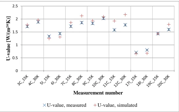
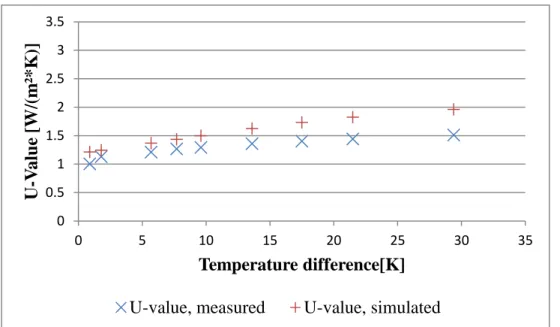
The U-values in the insulating and in the conducting states were determined experimentally and depend on the temperature difference between inside and outside. The very extensive and detailed measurement results are detailed in 0. The U-value functions chosen for the simulations were derived from the measurements of the first test models by fitting linear functions to the measurements values:
Figure 7 – U=f(ΔT) functions used for the TRNSYS simulations.
These functions were used to calculate the heat transfer through the element for every time step, depending on the temperature difference between room air temperature and exterior air temperature. The influence of the absorbed solar energy on the convective heat transfer has not been considered in this early stage, due to the facts that the absorbed energy in each layer was low and that the high U-value with high temperature differences in summer is mostly activated during night time.
Compared to the reference, following variants have been simulated:
- Variant A: The translucent element has a lower transmission within the solar spectrum, which is 4.5 % instead of 37.7 % for the glazing. The translucent element also has a lower U-value in the insulating state: about 1.0 W*m-2*K-1 by a temperature difference of ΔT=25 K instead of Ug=1.2 W*m-2*K-1 for the glazing. Thus, without even switching to the high U-value, replacing part of the façade by the translucent element has an influence on the simulation result. This influence is
U = 0.0086*Δθ + 0.7781 U = 0.0091*Δθ + 1.5883 U = 0.0682*Δθ + 0.7781 0 0.5 1 1.5 2 2.5 0.00 20.00 40.00 U -value [W/( m ²*K )] Δθ [K]
U-value, insulating state [W/(m²*K)]
U-value, conducting state, Δθ>13.7K [W/(m²*K)] U-value, conducting state, Δθ<13.7K [W/(m²*K)]
evaluated with control strategy A, where the U-value is never switched to the high value.
- Variant B: Variant B uses the previously defined U-value functions, with the following control strategy:
o Heating period :
When Text> Troom: high U-value. If not, low U-value.
o Cooling period:
When Text< Troom: high U-value. If not, low U-value.
The heating period is defined as the month where the heating load is superior to the cooling load. The rest of the time was then considered as the cooling period.
- Variant C:
This variant uses the same control strategy as variant B, but 3 W*m-2*K-1 is set as a constant value for the high U-value function. This arbitrary value corresponds to non-insulating double glazing. The goal was to simulate the potential of the element, if in the conducting state the convection is optimized or if a small ventilator is used. A small ventilator would allow us to get an U-value quite independent of the difference of temperatures at the boundaries, and would allow us to reach higher U-value due to higher convective heat transfer. This U-value was not measured in laboratory and is only theoretical.
In order to compare the effect of switching the U-value with a conventional solution: variant A, where the upper part of the window is replaced by the translucent element without switching, was simulated with a free-cooling strategy, in order to compare the effect of free cooling to the switchable U-value. For this variant, the air change rate of the room was raised from 2 to 4 vol/h when the outdoor air temperature was inferior to the indoor temperature. In order not to overcool the building, this strategy is only activated when the outdoor air temperature is above 19°C.
Daylight simulations of the office were made. The outputs of these simulations are the hours in the year where artificial lighting is needed. This output is then read by TRNSYS for every time step. The integration of daylight simulations into thermal simulations allows:
- A much better estimate of the electricity consumption for artificial lighting.
- More realistic values for the heat gains from artificial lighting in the building: when the artificial lighting is need.
For both electricity demand and additional heat gains due to lighting, a constant additional heat gain value of 13 W/m² is assumed as soon as the artificial light is required.
For the daylight simulation, a direct-hemispherical transmission value of τvis=0.053 was assumed for the façade element, based on the results of optical measurements presented in 2.3.1. To calculate this value, the transmission of glass, translucent insulation and glass were multiplied, without taking into account the multiple reflections and assuming a transmittance of 0.9 for the glass layer in the visible range.
These annual daylight simulations of the reference and the variants were performed using the raytracing software RADIANCE (Building Technologies Department, Lawrence Berkeley Laboratory 2014) in a preliminary step. The hourly outputs where then used in the TRNSYS simulation.
2.2.3 Results and discussion
Reference well-insulated south-oriented room:
The reference room has a low heating demand of 8.1 kWh*m-2*year-1. This corresponds to the Passive-House level. For this well-insulated, south oriented office room, the cooling load then prevails with 28.1 kWh*m-2*yr-1. The room has an office usage with 3 people between 7:00 and 18:00 on working days.
Variants with the translucent element with switchable U-value: The simulations of the described variants produced following results:
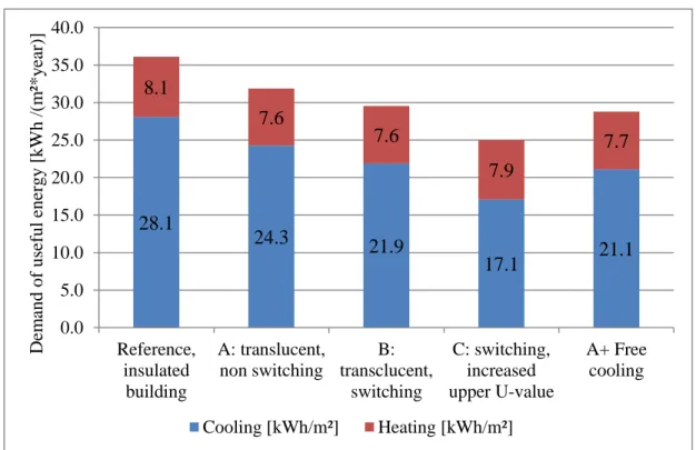
Figure 8 – Annual sum of heating and cooling demands for the insulated reference office and several variants, expressed in useful energy.
The difference between the reference and variant A show us that by replacing part of the glazing by our translucent element without switching, we decrease both the cooling and the heating demand. The decrease of the cooling demand is mainly due to the lower solar transmission, whereas the decrease of the heating demand is mainly due to the higher U-value of the element in the insulated state, compared to the window.
Variant B, where we switched between the high and low U-value, shows a decrease of 9.8 % of the cooling demand compared to variant A. This low reduction of the cooling demand is partly explained by the fact that in Germany, when the outside temperature is lower than the indoor temperature in summer, the difference is often low (under 5 K). According to Figure 7, the U-value is then near to 0.69 W*m-2*K-1, due to the linear
28.1 24.3 21.9 17.1 21.1 8.1 7.6 7.6 7.9 7.7 0.0 5.0 10.0 15.0 20.0 25.0 30.0 35.0 40.0 Reference, insulated building A: translucent, non switching B: transclucent, switching C: switching, increased upper U-value A+ Free cooling D em and o f usef ul ener g y [k Wh /( m ²*y ear )] Cooling [kWh/m²] Heating [kWh/m²]
interpolation chosen for this first approach. The assumption is that the heat transfer coefficient of the element with no temperature difference is the same in the insulating and conducting state, because in the conducting state there is no large-scale convection without the driving temperature difference. The consequence is that the heat transfer is low for these small temperature differences. In a further step, the heat transfers in the element have been modeled with a detailed model, showing an important increase of the U-value for low temperature difference.
Variant C, where an element is simulated with forced convection, shows a decrease of 29.6 % of the cooling demand compared to variant A. Compared to the reference, this represents a decrease of 39.1 %. In this case, the high U-value is not temperature dependent.
The comparison of variant A (with translucent element, without switching), variant B (switching U-value) and the free cooling (applied on variant A) shows us that the effect of the switching U-value is comparable with the effect of free cooling with a doubling of the air change rate from 2 to 4 vol*h-1. The savings of cooling demand are respectively 9.8 % and 13 %. In the case of free-cooling, the additional electrical consumption of the fan has to be taken into account. To estimate the additional consumption of the electrical fan, the fan consumption can be estimated at 0.45 W*m-3*h-1, which is the upper limit allowed for a german PassivHaus (Passivhaus Institut 2009). Based on this fan power and on the 1031 hours of functioning of the free cooling function, an additional electrical consumption of 3.2 kWh*m-2*yr-1 is calculated. This would more than compensate the thermal gain. To relativize these results, we can point out that the reference air change rate was already quite high (2 vol*h-1).
Concerning the variant B and C, the switch to the high U-value does not occur in the heating period. This is due to the fact than the situation θext>θint never occurs during these months for the Ludwigshafen’s weather data. During the cooling period, the high U-value is set more than 94 % of the time for variant B and C, so that a biannual control strategy may be considered, with the insulating state during the heating period and the conducting state during the rest of the time. A biannual switching would lead to a slightly variation of the cooling load from 21.89 kWh*m-2 to 21.90 kWh*m-2 while the heating demand stays the same. Concerning the use of dynamic switching during the cooling period, this is not efficient since when it is warmer outside, the temperature difference to the inside is small, and so the heat transfer coefficient of the element stays low. In this case, a biannual switching seems sufficient.
The influence on comfort has also been calculated, based on the adaptive model of the standard (DIN EN 15251:2007): this standard gives an upper limit for the operative temperature of the room, θi max, depending on the moving average of the external air temperature, θma, and includes the fact that the sensibility of people to indoor boundary
conditions depends on the external temperature. This implies that the occupants are able to interact with their environment by opening the windows. Following equations were used:
θi max= 0.33 ∗ θma+ 18.8 + 3 Equation 6
With the moving average θma given for a certain day by:
θma = 0.2 ∗ θed−1+ 0.8 ∗ θam−1 Equation 7
θma being the moving average of the external temperature of the day before, and θed-1 being the mean external temperature of the day before.
In (Kalz und Pfafferott 2014), different adaptive models, including the (DIN EN 15251:2007) model are compared with the Predicted Mean Vote (PMV) static model for eight European buildings. The conclusion were that the comfort requirement are similar in winter, but differ significantly in winter: since with the adaptive model the room temperature setpoints increase with higher ambient temperature, most of the building investigated complied with the limits of the adaptive models, but not with the ones of the static models. Other advantages of adaptive models is that they avoid the strong assumptions which have to be made when using the PMV models, such as the clo and met values, or the local air speed. In our case, using TRNSYS, following method was used to accurately calculate the inner glass temperature of the façade element and so the operative temperature in the room: the total heat flux to the interior was calculated using Equation 5. Then, this total heat flux was injected for every time step to a virtual window with a very important thermal resistance towards the exterior. The heat flux then integrally flows indoors, and, with the appropriate internal convective and radiative heat transfer coefficients, the correct element surface temperature is calculated. In the conducting state, while this is a good approximation between the two measured U-values, this might lead to differences for the range between no temperature difference and the first measurement point (see Figure 7).
Simulations without cooling have been performed, and the hours of the year where the operative temperature of the room is higher than the limit given by the standard have been summed, as shown in Figure 9 below.
Figure 9 – Hours in the year where the operative temperature is superior to the limit calculated with the DIN EN 15251 standard.
Variant A, where we only replace part of the window by the translucent element without switching to the high U-value, shows a decrease of the hours over variable operative temperature limit. This is due to the lower transmission of the translucent element.
Variant B shows a decrease of more than 193 hours compared to variant A, by switching between the low and high U-value. Variant C shows an even better improvement, with 115 hours of discomfort. Such an element could be even more competitive than a free-cooling strategy. This high impact of the switching on the comfort is due to the high influence of the façade’s internal surface temperatures on the operative temperature and on the comfort.
From the daylighting point of view, the replacement of the upper part of the window between the reference and the variants has of course consequences on the artificial lighting demand. Having an element that scatters the incoming light in the upper part of the façade should be of advantage compared to traditional windows since light could be send deeper in the room. However, due to the low visible transmittance of the insulation material, the artificial lighting demand increases from 8.2 kWh*m-2 to 13.3 kWh*m-2. This overcompensates the positive benefits of the switchable insulation on the cooling load. Possible solutions could be to exchange the translucent insulation material with another with a higher visible transmission, or to reduce the thickness of the insulation layer.
0 200 400 600 800 1000 1200 Reference, insulated building A: translucent, non switching B: transclucent, switching C: switching, increased upper U-value A + Free cooling 1005 563 370 115 192 H ours