1
Abstract — Cold start of proton exchange membrane fuel cells (PEMFCs) at sub-zero temperatures is perceived as one of the obstacles in their commercialization way in automotive application. This paper proposes a novel internal-based adaptive strategy for the cold start of PEMFC to control its operating current in real time in a way to maximize the generated heat flux and electrical power in a short time span. In this respect, firstly, an online parameter identification method is integrated into a semi-empirical model to cope with the PEMFC performances drifts during cold start. Subsequently, an optimization algorithm is launched to find the best operating points from the updated model. Finally, the determined operating point, which is the current corresponding to the maximum power, is applied to PEMFC to achieve a rapid cold start. It should be noted that the utilization of adaptive filters has escaped the attention of previous PEMFC cold start studies. The ultimate results of the proposed strategy are experimentally validated and compared to the most commonly used cold start strategies based on Potentiostatic and Galvanostatic modes. The experimental outcomes of the comparative study indicate the striking superior performance of the proposed strategy in terms of heating time and energy requirement.
Index Terms— Cold start, Proton Exchange Membrane Fuel Cell, Experimental approach, Adaptive strategies, Online identification.
1. INTRODUCTION
Passenger cars have been voiced as the most significant sources of transportation-related greenhouse gas emission. In this light, substituting fossil fuel-powered vehicles by green ones is an important measure to tackle this worldwide issue [1]. Electric and hybrid electric vehicles could be appropriate solutions. However, the latter still relies on fossil fuels and the former suffers from restricted driving range as well as long charging time. These pitfalls have paved the way for the emergence of fuel cell vehicles (FCVs). FCVs do not have the limitations of their competitors and benefit from definite merits, such as high efficiency, pollution free essence, and convenient maintenance, by comparison [2]. Among various types of fuel cells, PEMFC is regarded as the most potential one for automotive applications owing to its distinct
Real time adaptive efficient cold start strategy
for Proton Exchange Membrane fuel cells
A. Amamou
1,2,3, M. Kandidayeni
1,2,4, L. Boulon
1,2,5, S.Kelouwani
1,2,61
Institut de Recherche sur l’Hydrogène, UQTR, Trois-Rivières, QC G9A 5H7, Canada
2
Université du Québec à Trois-Rivières, 3351 Boulevard des Forges, Trois-Rivières, QC G9A 5H7, Canada
3[email protected] 4[email protected]
5[email protected] 6[email protected] POSTPRINT VERSION. The final version is published here:
Amamou, A., Kandidayeni, M., Boulon, L., & Kelouwani, S. (2018). Real time adaptive efficient cold start strategy for proton exchange membrane fuel cells. Applied Energy, 216, 21-30. CC BY-NC-ND 4.0 http://dx.doi.org/10.1016/j.apenergy.2018.02.071
2
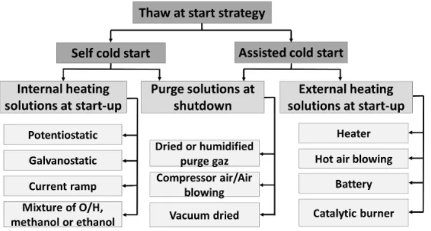
features such as high efficiency, high power density, and quick response [3]. FCVs have not nevertheless achieved their utmost market development in the automotive industry yet due to some barriers such as confined hydrogen and its infrastructure availability, high price, and limited extreme cold weather condition employment [4].The limitation of using PEMFCs in cold weather countries is mainly due to the well-known cold start problem [5]. Several researches have been conducted on the freezing mechanisms in PEMFCs. It has been found that the produced water inside the PEMFC freezes mainly in the cathode, which can prevent the passage of oxygen, increase membrane resistance and decrease the cathodic oxidation reaction [6-9]. These phenomena cause a significant voltage drop and fail the cold start [10-12]. The PEMFC cold start can be perceived as an interaction between the water produced by the electrochemical reaction and the required heat for warming up the cell [13]. If the produced water cannot be sufficiently removed and the generated heat is insufficient to raise PEMFC temperature above the freezing point, ice formation occurs in the cathode catalyst and gas transfer channels, resulting in cold start failure and PEMFC degradation [10, 14, 15]. In this regard, new purge and heating solutions, as shown in Fig. 1, have been recently developed to prevent the PEMFC from ice formation and develop cold start strategies [16]. Cold start strategies fall into two categories of Keep Warm and Thaw at Start. Keep Warm strategies revolve around the idea of heating the PEMFC during parking to avoid freezing [17-20]. Thaw at Start strategies are chiefly based on heating the PEMFC at start-up to raise its temperature above zero [21-36]. The previous work of the authors, regarding the comparison of the above-mentioned strategies, shows that Thaw at Start strategies are more adapted to be used for the cold start of private PEMFC vehicles, in which the parking time is almost unpredictable [37]. The Thaw at Start approaches fall into two groups according to their heating source. The first one, which is known as Assisted Cold Start strategies, uses an external heating source to generate heat and delivers it into the stack through a heat transfer medium [16]. The methods based on this group can be effective in terms of start-up time [22, 25, 27, 28, 34, 38]. However, adding heating material impacts the volume, weight, cost and energy efficiency of a PEMFC system [16]. In this regard, the second group, which is called Self-Cold Start strategies, has been introduced to compensate for the shortcoming of the first group. Self-Cold Start strategies mainly follow a two-stage procedure of purging during the shutdown, to prevent water accumulation and thus ice formation in the cathode catalyst layer, and internal-based heating during the start-up. The internal heating methods utilize the heat generated by the exothermic reaction and can be grouped into three sorts. The first one fixes current density (Galvanostatic startup) or cell voltage (Ptentiostatic startup), which favors the
3
production of the heat in the PEMFC. The second one, called Reactant Starvation, has an effect on stoichiometry and current density, and the third one employs a mixture of Oxygen/Hydrogen (O2/H2),
methanol, or ethanol to increase the stack temperature (Fig. 1). Among the internal heating solutions, Galvanostatic and Potentiostatic startups are the most commonly used solutions, and it is claimed that they are very effective in terms of energy requirement and system cost [16]. Lin et al. [30] and Hishinuma et al. [35] propose a Self-Cold Start strategy which consists in purging the PEMFC at shutdown and using the Galvanostatic solution at startup to heat the PEMFC. This strategy is effective for a cold start from -5°C but ineffective for lower temperatures. Guo et al. [26] attempt to increase the heat flux supplied by the Galvanostatic solution by introducing an O2/H2 mixture on the anode side in order to provide a Self-Cold
Start strategy from -20°C. This strategy requires a modification of the PEMFC system, and its performances depend strongly on the state of the PEMFC (temperature, membrane hydration, degradation). Another Self-Cold Start strategy, proposed in [21, 23, 31, 33], consists in purging the PEMFC at shut-down and using Potentiostatic mode at startup to escalate PEMFC temperature. This strategy is proven to be effective at cold start from -20°C, but its performances rely highly on the state of the PEMFC. Jiang et al. [32] and Gwak et al. [36] aim at optimizing Self-Cold Start strategies by suggesting to purge the PEMFC at shut-down and imposing a linear increase in current density at startup. The performance of this strategy is dependent on the membrane hydration and the PEMFC thermal mass [32]. Jian et al. [21] have compared Potentiostatic and Galvanostatic solutions and concluded that the former one is more advantageous than the latter regarding the heating time and energy requirements. In the light of the discussed articles, it can be concluded that the Potentiostatic based cold start solution is one of the best methodologies which has been proposed so far in terms of energy requirements and system cost. However, it has still a long way to go for automotive applications due to the several limitations such as demanding procedure for determining the required value of voltage, dependence on the states of the PEMFC, and being incapable of adapting to degradation and operating conditions variations.
The main contribution of this work is to put forward a novel adaptive cold start strategy in order to cope with the discussed shortcomings, such as fuel cell parameters variations, and also to ameliorate the cold start performances concerning the heating time and energy requirement. Therefore, a semi-empirical PEMFFC model coupled with an adaptive recursive least square (ARLS) is employed to keep track of the operating conditions and performance drifts in the first stage. Immediately afterwards, a procedure is proposed to conduct the cold start. To the best of the authors’ knowledge, this is one of the first attempts,
4
if any, to perform the internal PEMFC cold start while taking into account operating conditions uncertainties. The final results of this work have been experimentally validated by means of a developed test bench. Section 2 gives an account of the overall process of the proposed cold start methodology along with the PEMFC modeling and implementation of the adaptive algorithm. In Section 3, experimental outcomes are reported and explored. Finally, the conclusion is drawn in section 4 with some remarks and suggestions for further studies concerning this problem.
Fig. 1 Solution category chart for PEMFC cold start solutions and strategies (1 column)
2. ADAPTIVE COLD START STRATEGY
To enhance the PEMFC performance and avoid cold start failure, the produced heat from the fuel cell can be reused to warm up the PEMFC without external heating assistance. In order to minimize the heating time, it is crucial to maximize the generated heat by the exothermic reaction. It should be noted that drawing higher currents from the PEMFC leads to the generation of more heat. This is highly favorable for performing the cold start. However, an important limitation arises in this regard, which is the failure of PEMFC in providing high current loads at sub-zero temperature conditions, as discussed in [21]. Therefore, it is absolutely crucial to find the best current which can maximize the generation of residual heat while avoiding cold start failure.
During PEMFC operation, reduction in oxygen and hydrogen concentration naturally causes a mass transportation voltage drop. In fact, the rate at which the current is being drawn from the PEMFC affects directly the oxygen and hydrogen concentration. The reduction in oxygen and hydrogen concentration leads to a drop in hydrogen and oxygen pressure. This drop causes a cell voltage drop commonly known as concentration loss. The point which needs to be highlighted is that the concentration loss becomes significant at higher current levels, when the hydrogen and oxygen are used at higher rates [39, 40]. In this
5
respect, it can be stated that PEMFC systems have a limiting current (the current corresponding to the maximum power) and going beyond this limit results in the increase of concentration loss as well as PEMFC degradation. Therefore, it is suggested to operate the PEMFC at its maximum power (Pmax) during
the cold start. This mode of operation maximizes residual heat production and electrical power while avoiding concentration loss. Fig. 2 indicates the predicted polarization curve and its corresponded power curve to clarify the previously discussed points. As it can be seen in this figure, there is a clear connection between the maximum power point and occurrence of concentration loss. Moreover, the portion of thermal and electrical power as well as the heat generation related to the maximum power are shown.
Fig. 2 (a) PEMFC polarization curve , (b) PEMFC power curve (1 column)
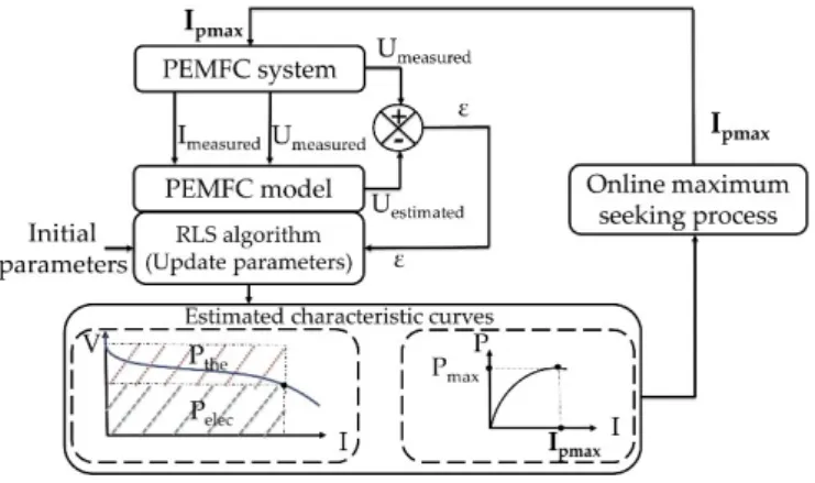
The proposed cold start methodology of this paper depends on the maximum power mode, which is based on the power map knowledge of the PEMFC. The power map-based strategy assumes that maximum power operating point is fixed. However, in reality, this maximum power is reliant on the operating conditions variations and aging phenomena and is not easy to be tracked [41, 42]. Moreover, during PEMFC cold start, the formed ice leads to increased mass transport loss which in turn adds to the variation of the maximum power operating point [43]. In this study, an online model identification method coupled to an optimization algorithm is used to track the PEMFC maximum power point in real time [39, 44-51]. The proposed model identification method allows a real-time PEMFC model identification to plot the PEMFC power curve with updated parameters and the employed optimization algorithm is responsible to find the current corresponding to the maximum power from the updated model. The identified current is finally applied to the real PEMFC system to perform the PEMFC cold start. The complete process is conducted online during the PEMFC cold start. Fig. 3 represents the explained process for the adaptive cold start of the PEMFC. Another aspect which plays a vital role in the functionality of the proposed adaptive strategy is to purge the PEMFC at shutdown and then seek the PEMFC maximum power at
6
startup. Purging the PEMFC just after the shutdown has several advantages, such as slowing down the ice formation in the cathode catalyst layer which allows the PEMFC to operate longer and generate more heat at cold start [16, 52, 53].
Fig. 3 Identification and control process (1 column)
2.1. Fuel cell modeling
The choice of a suitable model for online parameter identification process is critical due to the fact that the number of parameters and required sensors, as measurement inputs of the model, has a significant role in the computational time and precision of the model. The different employed PEMFC models presented in literature emulate the non-linear behavior of PEMFC and the dynamic evolution of these parameters during cold startup [54]. These dynamic models, which are known as mechanistic models, include different complex physical phenomena such as water transport, ice formation in the cathodic catalytic layer, electrochemical reactions, PEMFC heat exchanges, and so forth. PEMFC parameters of these models have been mostly identified at a given operating condition and are based on various assumptions [55, 56]. However, in real time application, the identified parameters are mainly influenced by the operating conditions, such as low temperature, and membrane humidity as well as PEMFC degradation [57]. The number of parameters of the PEMFC model is crucial in real time operation because many parameters would slow down the process and fewer parameter give a lack of precision for control. In this regard, a semi-empirical model, which is based on the physical relationships assisted by experimental data and represents the elemental electrochemical facets of FCs such as polarization curve, is chosen to describe the PEMFC behavior. This model benefits from a physical meaning and has a relative short computational time. It has been developed by Squadrito et al. [58] and is presented by an analytical expression, allowing to define the output voltage of the stack as a function of the current delivered by the stack. The cell potential (Vcell) is calculated by subtracting the activation (ξact), ohmic (ξohm), and concentration (ξconc) overvoltages
7
from the Nernst potential (Enernst). These physical meanings are very interesting to evaluate the relevance
of the results.Squadrito's model is presented as follows: 𝑉𝑐𝑒𝑙𝑙 = 𝐸𝑛𝑒𝑠𝑛𝑠𝑡 − 𝜉𝑎𝑐𝑡 − 𝜉𝑜ℎ𝑚 − 𝜉𝑐𝑜𝑛𝑐
𝑉𝑐𝑒𝑙𝑙 = 𝑉0 − 𝑏 log(𝑖𝑓𝑐) − 𝑟 𝑖𝑓𝑐 + 𝛼(𝑖𝑓𝑐)𝑘 log (1 − 𝛽𝑖𝑓𝑐) (1)
Where V0 is the thermodynamic potential of the chemical reaction inside the PEMFC. It depends on the
PEMFC temperature and the partial pressure of O2 and H2 [59]. The activation overvoltage, presented by
𝑏 log(𝑖𝑓𝑐), is the sum of the anode and cathode overvoltage [58]. The parameters 𝑖𝑓𝑐 and b are defined as the current density and an empirical constant dependent on PEMFC temperature, PEMFC degradation and membrane humidity respectively. The ohmic overvoltage, indicated by 𝑟 𝑖𝑓𝑐, is defined as the resistance of the proton and electron transfer inside the membrane and the electrodes. It depends mainly on the internal membrane resistance (r). The parameter r depends on membrane conductivity, thickness of the membrane and PEMFC temperature and its range can be approximated by the slope of the polarization curve in the ohmic region. The concentration overvoltage, formulated by − 𝛼(𝑖𝑓𝑐)𝑘 log (1 − 𝛽𝑖𝑓𝑐), arises when the PEMFC is in high current density. The variables 𝛼 and 𝑘 are respectively a parameter related to the diffusion mechanism (between 0.3 to 1.8) and a dimensionless number related to the water flooding phenomena (between 1 to 4) [58]. The parameter 𝛽 is the inverse of the limiting current density (A-1cm-2).
It is crucial that Squadrito's model considers concentration overvoltage because it helps identifying the PEMFC maximum power point with an acceptable precision. Squadrito's model needs few sensors, only current and voltage measurements, and four parameters to be identified as V0, b, r and a.
The utilized semi-empirical model describes the behavior of the fuel cell based on the prediction of polarization curve. In this respect, an investigation of the influence of each parameter on the output voltage of PEMFC, which consists of open circuit voltage (OCV), activation loss (AL), ohmic loss (OL), and concentration loss (CL), becomes feasible. The voltage model is utilized for this analysis due to the fact that the estimation of power, which is the base of proposed cold start strategy in this paper, is premised upon the estimation of voltage. Hence conducting the analysis of variance (ANOVA) remains valid for the voltage model. To do so, the decomposition by ANOVA with the Sobol method is employed to quantify the influence of parameters on the PEMFC output voltage. The following formulations show how the introduced fuel cell model can be used to calculate the total variance of the PEMFC voltage (𝑉𝐶𝑒𝑙𝑙,𝑤,𝑥,𝑦,𝑧) and the variance of each introduced parameter (Var (V0), Var (b), Var (r), and Var (𝛼)).
8
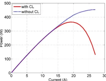
𝑉𝐶𝑒𝑙𝑙,𝑤,𝑥,𝑦,𝑧= 𝑉0𝑤− 𝑏𝑥log(𝑖𝑓𝑐) − 𝑟𝑦𝑖𝑓𝑐+ 𝛼𝑧𝑖𝑓𝑐𝑘 log (1 − 𝛽𝑖𝑓𝑐) (2) 𝑉𝑎𝑟 (𝑉𝑐𝑒𝑙𝑙,𝑤,𝑥,𝑦,𝑧) = ∑𝑁𝑤=1∑𝑁𝑥=1∑𝑁𝑦=1∑𝑁𝑧=1(𝑉𝐶𝑒𝑙𝑙,𝑤,𝑥,𝑦,𝑧−𝑉̅𝐶𝑒𝑙𝑙,….)2 𝑁4 (3) 𝑉𝑎𝑟 (𝑉0) = ∑𝑁𝑤=1(𝑉̅𝐶𝑒𝑙𝑙,𝑤…−𝑉̅𝐶𝑒𝑙𝑙,….)2 𝑁 (4) 𝑉𝑎𝑟 (𝑏) =∑𝑁𝑥=1(𝑉̅𝐶𝑒𝑙𝑙,.𝑥..−𝑉̅𝐶𝑒𝑙𝑙,….)2 𝑁 (5) 𝑉𝑎𝑟 (𝑟) =∑ (𝑉̅𝐶𝑒𝑙𝑙,..𝑦.−𝑉̅𝐶𝑒𝑙𝑙,….) 2 𝑁 𝑦=1 𝑁 (6) 𝑉𝑎𝑟 (𝛼) =∑𝑁𝑧=1(𝑉̅𝐶𝑒𝑙𝑙,...𝑧−𝑉̅𝐶𝑒𝑙𝑙,….)2 𝑁 (7) Fig. 4 represents the effect of each parameter on the voltage estimation. According to this figure, OCV and OL have the greatest impacts on the output voltage by almost 80% and 17% respectively. The CL has a minimal effect on the output of the PEMFC model and, from the statistical point of view, can be assumed as constant. However, constant assumption of the CL, which is related to the mass transport, makes the prediction of the real maximum power highly challenging. Fig. 5 shows the estimated maximum power of the fuel cell with and without consideration of the CL. As it is seen in this figure, the maximum power estimation without CL is not very precise. In this regard, all the parameters of the model need to be estimated online by ARLS to enhance the accuracy of the outcomes.9
Fig. 5 Estimated PEMFC power curves at 5°C with and without CL
2.2. Online identification algorithm
The PEMFC identification process is carried out in an online manner, where the experimental data, which are current, voltage, is used to update the PEMFC model parameters. In this context, recursive algorithms are suited to real-time applications since they can update the model as the experimental data comes in after each sample. Among a large number of recursive identification algorithms, Recursive Least Squares (RLS) is one of the most popular techniques that brings about interesting results for real-time application [60]. However, the classic RLS algorithm may lose its accuracy of estimation in case of tracking time-varying systems like PEMFCs [61]. In this paper, the estimator is required to track changes in a set of time-varying parameters. Hence a forgetting factor µ is considered to account for more recent measurements [62, 63].There are many ways to update the forgetting factor. The most adapted one to the needs of this paper is the Directional Forgetting factor that forgets the information only in the directions in which new information is gathered. The chosen forgetting factor assures the convergence of the estimations and helps to track significant changes in the parameters [61]. In addition, Bierman decomposition is used for the covariance matrix in order to guarantee a positive semi-definite function and avoid numerical instability [64]. The ARLS algorithm can be formulated as follows.
𝐽(𝑘) = ∑𝑘 𝜕𝑘−𝑖
𝑖=0 𝑒𝑖2
(8)
10
x(𝑘)=[1, 𝑙𝑜𝑔(𝑖𝑃𝐸𝑀𝐹𝐶), 𝑖𝑃𝐸𝑀𝐹𝐶, 𝑖𝑃𝐸𝑀𝐹𝐶𝑘 𝑙𝑜𝑔 (1 − 𝛽𝑖𝑃𝐸𝑀𝐹𝐶)] (10) 𝐾(𝑘 + 1) = 𝑃(𝑘) 𝑥(𝑘+1) 1 + 𝑥(𝑘+1)𝑇 𝑃(𝑘) 𝑥(𝑘+1) (11) 𝑃(𝑘 + 1) = 𝑃(𝑘 + 1) − 𝑃(𝑘)−𝐾(𝑘+1) 𝑥(𝑘+1)𝑇 𝑃(𝑘) µ(𝑘)−1+𝑥(𝑘+1)𝑇 𝑃(𝑘) 𝑥(𝑘+1) (12) µ(𝑘 + 1) = { 𝜕(𝑘 + 1) − 1−𝜕(𝑘+1) 𝑥(𝑘+1)𝑇 𝑃(𝑘) 𝑥(𝑘+1) ; 𝑠𝑖 𝑥(𝑘 + 1) 𝑇 𝑃(𝑘) 𝑥(𝑘 + 1) > 0 1 ; 𝑠𝑖 𝑥(𝑘 + 1)𝑇 𝑃(𝑘) 𝑥(𝑘 + 1) = 0 (13) 𝑒(𝑘 + 1) = 𝑌(𝑘 + 1) − 𝑥(𝑘 + 1)𝑇 ℎ(𝑘)(14) ℎ(𝑘 + 1) = ℎ(𝑘) + 𝐾(𝑘 + 1) 𝑒(𝑘 + 1)
(15)
Where J(k) is the objective function that should be minimized, K(k) denotes the gain matrix, P(k) is the covariance matrix of the estimated parameters, h(k) is the vector that contains the estimated parameters, x(k) is the data or regression vector, e(k) is the prediction error and µ(k) is the directional forgetting factor. Eq. (2-9) are solved recursively to define h(k).
The ARLS algorithm is based on continuous updating of the model parameters h(k). Therefore, the initial parameters h(0) should be chosen close to the reality to avoid algorithm divergence. In this regard, a preprocessing of data is performed in this paper to avoid increasing the computational time or divergence and also get close to highly realistic results. The preprocessing of data is conducted by the Curve Fitting Toolbox™ of MATLAB software. This toolbox utilizes the least square methods to fit the data. Fitting requires a parametric model which can relate the real data to the predictor data. In this work, the employed fuel cell model is linear in coefficients. Therefore, linear least square, which minimizes the summed square of the difference between the observed response value and the fitted response value, is used to fit the model to experimental data. The utilized experimental data in the preprocessing stage comes from a conducted test at an initial temperature of -20°C to get the polarization curve of the fuel cell, which is a proper representative of its behavior. The recursive estimation of the PEMFC parameters by the ARLS method is tested in simulation and proven to be efficient in terms of computational time and precision.
11
3. EXPERIMENTAL RESULTS DISCUSSION
3.1. Test bench
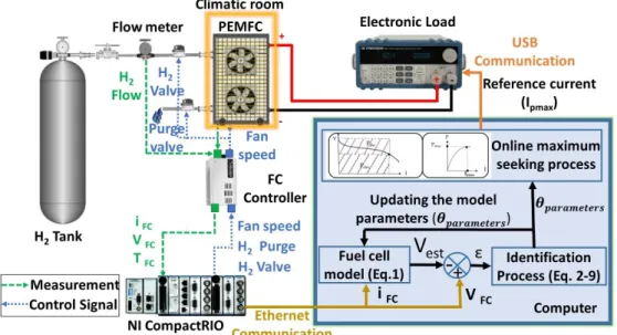
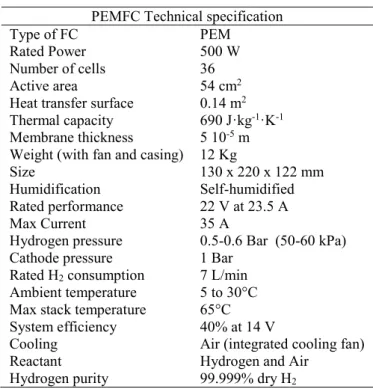
The test bench used to test and validate the adaptive cold start strategy is presented in Fig. 6. The test bench is developed at the UQTR Hydrogen Research Institute (HRI), and it is composed mainly of an open-cathode PEMFC with a nominal power of 500 W and an active area of 54 cm2. The PEMFC characteristics
are presented in Table 1. The open-cathode PEMFC is self-humidified and air-cooled. The used fuel cell is called open-cathode PEMFC (or air-breathing PEMFC) because it includes 2 fans to supply the cathode with oxygen instead using compressed oxygen. Moreover, the fans are used to cool down the stack in case of overheating. The PEMFC fans speed controls the flow rate of air supplied to the cathode. The speed of the fans depends strongly on the power delivered by the PEMFC and the stack temperature. At low temperatures, a high fans speed increases the flow rate of cold air, which cools the PEMFC and influences its cold start capability. Therefore, several tests have been conducted to identify the minimum fans speed that provide enough oxygen to the PEMFC for all of these power ranges. The minimum operating fans speed supplies the PEMFC with a constant air flow of 17 l/s. In the anode side, the PEMFC is equipped with 2 valves. The anode inlet valve allows feeding the PEMFC with dry hydrogen. The hydrogen flow rate changes with the power output, and it is usually between 0 and 11.67 10-2 l/s. The anode outlet valve
is used to purge the residual water during PEMFC operation. In addition, it was shown in literature that Nitrogen (N2) circulates through the polymer-electrolyte membrane from the cathode air to the anode side, adding to the hydrogen gas in the anode channels [65].The buildup of N2 in the recirculating anode gas reduces the PEMFC performance [66]. Consequently, a portion of the hydrogen gas has to be purged to prevent excessive buildup of N2 in the anode side. The anode side has to be purged recurrently in order to remove accumulated water and nitrogen. Therefore, the PEMFC is purged every 10 seconds for a purge duration of 10 ms in order to refill the anode volume with fresh hydrogen. The hydrogen exhaust flow during the purge depends on the pressure difference between the environment (1 bar) and the anode side (1.5 bar as advised by the manufacturer) and the state of the purge valve. In addition, the pressure difference between the anode and the cathode must not exceed 0.5 bar to avoid damaging the membrane. The control of the purge valve, fan speed, hydrogen valve and the acquisition of data (temperature, current, voltage, hydrogen flow) are performed through an embedded computer NI CompactRIO 9022. A programmable load manufactured by BK Precision with a maximum power of 1200 W is connected to the PEMFC in order to emulate the behavior of an automobile traction chain. The PEMFC being tested is placed inside
12
an environmental chamber, which is used to set the start-up temperatures. It should be noted that the ARLS algorithm is developed in MATLAB and introduced in LabVIEW program via MathScript RT Module. In the first stage, the ARLS algorithm receives the PEMFC current and voltage data from the real PEMFC via Ethernet communication every 100 ms. In the second stage, the ARLS algorithm estimates the parameters, V0, b, r and 𝛼. In the third stage, the estimated parameters are used to plot the power versus current curve and the current corresponded to the maximum power is identified and sent to the load via USB communication. The process is performed in real-time. It should be reminded that the employed PEMFC in the test bench cannot supply 500 W, as opposed to the mentioned rated power in the characteristics. It is due to the fact that this PEMFC has been used for some years and its maximum power has decreased due to degradation. However, it can supply enough power for the purpose of this work.
13
Table 1 PEMFC characteristics
PEMFC Technical specification Type of FC
Rated Power PEM 500 W
Number of cells 36
Active area
Heat transfer surface Thermal capacity Membrane thickness
Weight (with fan and casing) Size Humidification 54 cm2 0.14 m2 690 J·kg-1·K-1 5 10-5 m 12 Kg 130 x 220 x 122 mm Self-humidified Rated performance 22 V at 23.5 A Max Current 35 A Hydrogen pressure
Cathode pressure 0.5-0.6 Bar (50-60 kPa) 1 Bar Rated H2 consumption 7 L/min
Ambient temperature 5 to 30°C Max stack temperature
System efficiency 65°C 40% at 14 V Cooling
Reactant Hydrogen purity
Air (integrated cooling fan) Hydrogen and Air
99.999% dry H2
3.2. Procedure
The experimental procedure for adaptive cold start strategy consists of three major steps: purging, cooling down, and startup. The purge duration (10 s) and cooling time (4 h) have been justified to ensure consistent cell conditions before the cold start.
1. The purge procedure is premised upon activating the purge valve for 10 seconds to evacuate the residual water after PEMFC shutdown. This purge procedure is effective in reducing liquid water and in improving the cold start performance.
2. Upon completing the purging step, the temperature inside the environmental chamber is set to the desired start-up temperatures to cool down the PEMFC for 4 h.
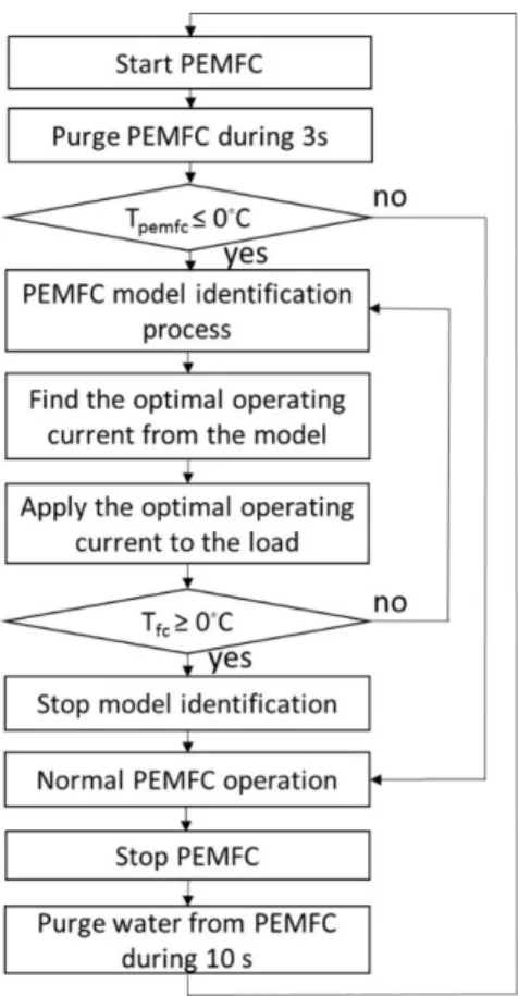
3. Once the cooling down step is completed, the control process is launched to warm up the PEMFC. The control process can be broken down into three steps. Firstly, the parameters of the PEMFC model are updated using ARLS algorithm to predict the PEMFC polarization curve and power curve during cold start. Secondly, the optimal operating current is obtained from the model. Lastly, the optimal current is applied to the real PEMFC system. The complete process
14
is executed on-line until PEMFC temperature reaches the melting point of ice. The flowchart of the adaptive cold start strategy is represented in Fig. 7.
Fig. 7 Flowchart of Adaptive Cold Start Strategy (1 column)
The PEMFC parameters such as hydrogen pressure, fan speed and purge time are chosen after a parametric study which allowed to identify the best starting conditions for PEMFC at low temperatures. 3.3. Experimental results
The achieved results from the conducted tests on the developed adaptive cold start strategy are explored in this section. The first part of the analysis is related to the customization and validation of the utilized adaptive filter algorithm and suggested cold start strategy. In this part, the accuracy of voltage estimation as well as the evolution of the parameters and some other experimental characteristics of the PEMFC are represented. Moreover, the performance of the proposed adaptive cold start strategy is evaluated. The second part of the analysis deals with performing a comparative study. In this section, the outcomes of the proposed adaptive cold start strategy are compared with the results of the two most commonly investigated cold start strategies, namely Potentiostatic and Galvanostatic, in the literature.
15
3.3.1. Customization and validation
Since the proposed cold start strategy is based on power estimation, it must be ensured that ARLS algorithm is able to estimate PEMFC voltage close to the measured voltage. It should be noted that power is calculated by means of estimated voltage. In this respect, a random current profile is imposed to the PEMFC as shown in Fig. 8a. The measured and estimated voltage are compared in Fig. 8b. The percentage of estimation error, which is shown in Fig. 8c, confirms the adequate accuracy of ARLS algorithm in estimating the output voltage of the PEMFC.
Fig. 8 Experimental validation of RLS (1 column)
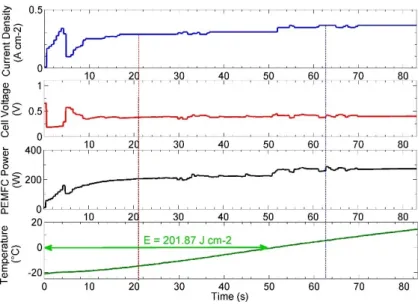
Fig. 9 represents the conducted test to evaluate the performance of the suggested adaptive methodology for the PEMFC cold start. It should be noted that prior to performing this test, the same procedure as explained in section 3.2 has been followed. This test has been carried out with the initial temperature of -20°C. According to Fig. 9, the temperature has reached the melting point, 0°C, at almost 50 seconds with an energy consumption of 201.87 J cm-2. Looking more closely at Fig. 9, it can be observed that
PEMFC optimum current increases during the first few seconds, almost five seconds, followed by a rapid drop, and then it remains almost stable. It is due to the fact that current density directly reflects the water and heat production rates which change significantly during the cold start process [16]. It should be noted that the current density is high and the membrane is dry with more water absorption in the beginning. Dry membrane decreases PEMFC performance, which is reflected from the rapid drop of PEMFC voltage in the beginning. Due to the deterioration of PEMFC performances, the algorithm decreases PEMFC current to follow PEMFC parameters variations. After the occurrence of the current drop at almost fifth second, the algorithm increases the current again. This increase is caused by the membrane hydration and temperature enhancement, which lowers the ohmic resistance and enhances the kinetics reaction. At
16
the moment of ice melting (t=52 s), an increase in current density can also be observed, mainly due to the sudden change of ice and liquid volume fractions. Afterwards, the current density and cell voltage become relatively stable. For the adaptive cold start mode, the PEMFC performance improvement is caused by the membrane hydration and temperature increment.
Fig. 9 Evolution of cell voltage, current density, PEMFC temperature and PEMFC power during adaptive cold start (1 column)
Fig. 10 shows the variation of the parameters during the conducted adaptive cold start test. It can be stated that the employed ARLS algorithm is perfectly capable of tracing the time-varying parameters of the PEMFC. Indeed, these variations indicate that the selected semi-empirical model and the integrated adaptive filter are successfully dealing with the performance drifts of the PEMFC during the cold start.
17
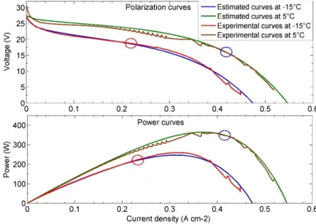
One important point that needs to be investigated is the influence of temperature variation in the estimation of maximum power. In fact, a variation of temperature exerts a significant influence on the maximum deliverable power of the fuel cell, and hence it is highly important to have an accurate prediction of the fuel cell behavior while the operating temperature change. In this regard, two sets of parameters, which have been obtained by the parameter estimation method in two different operating temperatures, have been utilized to plot the polarization curves and maximum power curves of the fuel cell, as shown in Fig. 11. The first considered data is related to the temperature of -15°C at 21 seconds and the second one is for the temperature of 5°C at 63 seconds. These two sets of data have been collected to plot power and polarization curves. As expected from literature, an increase is seen in the amount of power when the temperature rises. It can be seen that the required current density for achieving the maximum power increases from 0.32 A cm-2 at -15℃, to reach 249 W, to 0.37 A cm-2 at 5℃, to attain
363 W. It can be inferred from the discussed result that the obtained parameters successfully provide the maximum power and characteristic curves which vary depending on the operating temperature.
Fig. 11 Experimental and estimated PEMFC characteristic curves at -15°C and 5°C (1 column)
Table 2 provides information on the values of the two sets of the collected data for evaluating the maximum power estimation at various temperatures. This table presents a good opportunity to analyze the evolution of membrane resistance (r) value. Actually, since the increase of the temperature favors the hydration of the membrane, it is observed that the resistance of the membrane decreases from 0.3 Ω to
18
0.23 Ω due to the temperature increase from -15°C to 5°C. The range of membrane resistance parameter is validated by the value of the slope of experimental polarization curve in the ohmic region.
Table 2 Two sets of fitting parameters collected at -15°C (t=21 s) and 5°C (t=63 s)
V0 b r a
-15°C 0.773 0.027 0.3 10.32
5°C 0.775 0.022 0.23 7.32
Table 3 gives an account of the heating time and energy requirements for the adaptive cold start strategy from different initial temperatures. It indicates thata higher startup temperature decreases heating time and energy requirement. The heating time changes almost linearly with the startup temperature. The proposed cold start strategy can adapt to the variation of the operating conditions (Initial temperature, membrane humidity…) and the degradation of the PEMFC.
Table 3 Effect of initial temperature on cold start performances
Temperatures Heating time Energy requirement
- 6.7°C 20.2 s 71.23 J cm-2
-10.4°C 29.4 s 112.98 J cm-2
-13.5°C 36.9 s 133.94 J cm-2
-20°C 54 s 201.87 J cm-2
In the light of the investigated results, several advantages can be mentioned regarding the proposed adaptive cold start strategy. First of all, it is strikingly economical in terms of energy consumption. Moreover, it can satisfy the international PEMFC vehicle requirements which demand 50% of the PEMFC maximum power in less than 30 seconds for a cold start from -20°C [67]. This proposed adaptive cold start strategy is also independent ofcomplex PEMFC modeling and provides a cold start solution adaptable to the state of the PEMFC. Another worth mentioning aspect of this strategy is maximizing heat flux and electrical power provided by the PEMFC while avoiding the PEMFC operation at low voltage regions. From an industrial point of view, it can be stated that the suggested adaptive cold start method is simple to implement in a real PEMFC system and requires minimal user intervention, which minimizes manipulation and parameterization errors.
19
3.3.2. Comparative study
Literature consideration shows that most of the existed cold start strategies are based on the well-known constant voltage (Potentiostatic) and constant current (Galvanostatic) modes. Contrary to the proposed adaptive strategy, Potentiostatic and Galvanostatic modes work with fixed cold start parameters (current or voltage) to promote heat generation during PEMFC cold start. To put the finishing touches on the performance evaluation of the suggested adaptive cold start strategy of this work, a comparative study has been carried out to illustrate the distinguishing features of the three mentioned strategies. The experimental procedure for Potentiostatic and Galvanostatic startups consist of three major steps. Purging and cooling down, which are similar to adaptive strategy procedure, and then demanding a constant current or voltage form the PEMFC. It is evident that solely the startup stage is different from adaptive strategy procedure. The Potentiostatic voltage value and Galvanostatic current value have been selected after performing several tests to ensure a good cold start performance. Currentdensity is set to 222 mA cm-2 for Galvanostatic mode, and cell voltage is set to 0.38 V for Potentiostatic mode. It should be noted
that current density can be at high levels during Galvanostatic start-up. However, when the current density is at its maximum, the output voltage drops to 0 which is not a practical operating voltage. For Potentiostatic start-up, a reasonably low but practical voltage of 0.38 V is used to ensure high current densities. Fig. 12 shows the results of the conducted tests based on the provided information about voltage and current levels for Galvanostatic and Potentiostatic startups. Fig. 12 demonstrates the evolution of voltage in Galvanostatic mode, which is related to the demand of 222 mA from the PEMFC, and current in Potentiostatic mode, which comes from the desired voltage level (0.38 V) in the PEMFC. Looking more closely at Fig. 12, it is observed that the current density depends strongly on the hydration of the membrane during Potentiostatic startup. In the beginning, the current density is low because the membrane is initially dry. Afterwards, due to the produced water in the first stage, the membrane is gradually hydrated, and its protonic resistance is decreased. This phenomenon favors the increase of the current and consequently the heat flux and the temperature increase considerably. However, the current density is independent of the hydration of the membrane during Galvanostatic mode since it is constant during cold start. Eq. (16) can explain the evolution of PEMFC temperature during Galvanostatic startup which increases slowly as a result of declined heat flux caused by cell voltage increase.
𝑄
𝑡ℎ= (
𝛥𝐻20
Fig. 13 represents the corresponded temperature evolutions of each cold start technique. According to this figure, the melting point has been reached at 102 and 220 seconds in Potentiostatic and Galvanostatic modes respectively.
Fig. 12 Evolution of cell voltage and current density during Galvanostatic and Potentiostatic start-up (1 column)
Fig. 13 Evolution of cell temperature during Galvanostatic, Potentiostatic and Adaptive cold start (1 column)
Form the conducted test, it can be concluded that low current density in Galvanostatic startup prolongs the heating time of the PEMFC, which makes this solution less interesting for the cold start of PEMFC in a vehicular application. On the other hand, Potentiostatic startup provides a higher level of heat than Galvanostatic due to its high current density. However, the performance of Potentiostatic technique mainly depends on constant cell voltage, which affects greatly the evolution of current density and cell
21
temperature. The value of this voltage depends on the parameters of the PEMFC and requires several tests to be identified.
Contrary to Potentiostatic and Galvanostatic techniques, the proposed adaptive cold start strategycopes with fuel cell parameters variations during cold start and keeps the current density at high levels, leading to PEMFC performance improvement caused by membrane hydration and temperature increment. This cold start strategy based on maximum power mode not only provides the PEMFC maximum power but also produces high reaction heat during cold start-up. Fig. 14 shows the comparison of the heating time and energy requirements of the different cold start strategies. It can be seen that heating time of Galvanostatic and Potentiostatic modes is much longer than the proposed adaptive cold start strategy. Moreover, energy consumption of adaptive cold start strategy is about 201.87 J cm-2 compared to 481.56
J cm-2 and 873.36 J cm-2 of the Potentiostatic and Galvanostatic approaches respectively. According to
the comparison of the three cold start strategies, it can be concluded that adaptive cold start strategy is more advantageous than Potentiostatic and Galvanostatic strategy in terms of heating time, energy requirements. It is also evident that this adaptive strategy does not have the problem of adaptability and repeatability compared to its competitors.
4. CONCLUSION
In this paper, a new approach for PEMFC cold start has been proposed premised on online parameter identification. In this respect, a semi-empirical model is selected to predict the behavior of the PEMFC by means ARLS algorithm. To the best of authors’ knowledge, this is the first proposed adaptive strategy for internal heating of a PEMFC during the cold start. The adaptive algorithm updates the model parameters in order to trace the performance drifts of the PEMFC due to degradation and operating
Adaptive cold start Potentiostatic cold start Galvanostatic cold start 54 102 220 201,87 481,56 873,36 Heating time (s) Required energy (J cm-2)
Fig. 14 Performance comparison of different cold start strategies (1 column)
22
conditions variation, and the model provides the characteristic curves of the PEMFC, such as polarization and power curves, in real-time. The maximum power point is determined with the help of an optimization algorithm from the power curve, and its corresponding power is demanded from the PEMFC during the cold start. It should be noted that the process of the cold start is performed based on purging the PEMFC at shutdown and heating it up at startup. The whole explained process of assigning the corresponding current to the maximum power is done during the startup stage at low temperature. The proposed adaptive strategy has been implemented in a developed test bench, and its performance has been compared to two renowned cold start techniques, namely Potentiostatic and Galvanostatic, in terms of heating time and energy consumption. The achieved experimental results confirm the improvement of over 50% regarding the defined comparison criteria. In addition, the existed startup techniques are based on a pre-calculated set of rules known in advance. However, the adaptive strategy constantly modifies these rules online according to measurements carried out on the real PEMFC. The implementation of the proposed adaptive cold start strategy is very convenient in a real PEMFC in vehicular application since it requires minimal user intervention.
The outcomes of this paper put forward the following directions for future studies:
Integration of a thermal model into the employed voltage model of PEMFC to increase the precision of characteristics prediction.
The application of the proposed strategy in other fuel cells, different technologies and power ranges, and the impact of the strategy on the PEMFC lifetime.
ACKNOWLEDGEMENTS
This work was supported in part by the Bureau de l’éfficacité et de l’innovation énergétique, Ministère des Ressources Naturelles et de la Faune du Québec and in part by the Natural Science and Engineering Research Council of Canada.
REFERENCES
[1] J. Jaguemont, L. Boulon, and Y. Dubé, "A comprehensive review of lithium-ion batteries used in hybrid and electric vehicles at cold temperatures," Applied Energy, vol. 164, pp. 99-114, 2/15/ 2016.
[2] Y. Wang, K. S. Chen, J. Mishler, S. C. Cho, and X. C. Adroher, "A review of polymer electrolyte membrane fuel cells: Technology, applications, and needs on fundamental research," Applied Energy, vol. 88, pp. 981-1007, 4// 2011.
23
[3] M. Kandi Dayeni and M. Soleymani, "Intelligent energy management of a fuel cell vehicle based on traffic condition recognition," Clean Technologies and Environmental Policy, vol. 18, pp. 1945-1960, August 01 2016.
[4] Q. Yan, H. Toghiani, Y.-W. Lee, K. Liang, and H. Causey, "Effect of sub-freezing temperatures on a PEM fuel cell performance, startup and fuel cell components," Journal of Power Sources, vol. 160, pp. 1242-1250, 10/6/ 2006.
[5] Y. Tabe, M. Saito, K. Fukui, and T. Chikahisa, "Cold start characteristics and freezing mechanism dependence on start-up temperature in a polymer electrolyte membrane fuel cell," Journal of Power Sources, vol. 208, pp. 366-373, 2012.
[6] J. Hou, B. Yi, H. Yu, L. Hao, W. Song, Y. Fu, et al., "Investigation of resided water effects on PEM fuel cell after cold start," International Journal of Hydrogen Energy, vol. 32, pp. 4503-4509, 12// 2007.
[7] M. Oszcipok, D. Riemann, U. Kronenwett, M. Kreideweis, and M. Zedda, "Statistic analysis of operational influences on the cold start behaviour of PEM fuel cells," Journal of Power Sources, vol. 145, pp. 407-415, 8/18/ 2005.
[8] K. Han, B. K. Hong, S. H. Kim, B. K. Ahn, and T. W. Lim, "Influence of anisotropic bending stiffness of gas diffusion layers on the degradation behavior of polymer electrolyte membrane fuel cells under freezing conditions," International Journal of Hydrogen Energy, vol. 36, pp. 12452-12464, 9// 2011.
[9] W. Schmittinger and A. Vahidi, "A review of the main parameters influencing long-term performance and durability of PEM fuel cells," Journal of Power Sources, vol. 180, pp. 1-14, 5/15/ 2008.
[10] Z. Wan, H. Chang, S. Shu, Y. Wang, and H. Tang, "A review on cold start of proton exchange membrane fuel cells," Energies, vol. 7, pp. 3179-3203, 2014.
[11] S. He and M. M. Mench, "One-dimensional transient model for frost heave in polymer electrolyte fuel cells I. Physical model," Journal of The Electrochemical Society, vol. 153, pp. A1724-A1731, 2006.
[12] P. Pei and H. Chen, "Main factors affecting the lifetime of Proton Exchange Membrane fuel cells in vehicle applications: A review," Applied Energy, vol. 125, pp. 60-75, 2014.
[13] S. Huo, N. J. Cooper, T. L. Smith, J. W. Park, and K. Jiao, "Experimental investigation on PEM fuel cell cold start behavior containing porous metal foam as cathode flow distributor," Applied Energy, vol. 203, pp. 101-114, 2017.
[14] J. Wang, "System integration, durability and reliability of fuel cells: Challenges and solutions," Applied Energy, vol. 189, pp. 460-479, 2017/03/01/ 2017.
[15] Y. Wang, P. P. Mukherjee, J. Mishler, R. Mukundan, and R. L. Borup, "Cold start of polymer electrolyte fuel cells: Three-stage startup characterization," Electrochimica Acta, vol. 55, pp. 2636-2644, 3/1/ 2010.
[16] A. A. Amamou, S. Kelouwani, L. Boulon, and K. Agbossou, "A Comprehensive Review of Solutions and Strategies for Cold Start of Automotive Proton Exchange Membrane Fuel Cells," IEEE Access, vol. 4, pp. 4989-5002, 2016.
[17] W. S. Wheat, M. A. Meltser, and D. A. Masten, "Fuel cell energy management system for cold environments System for cold environment," US Patent 6,727,013 B2, 2004.
[18] B. J. Clingerman, J. R. Kolodziej, D. S. Kilmer, P. A. Rapaport, D. S. Mathews, S. Kocha, et al., "Fuel cell system water management strategy for freeze capability," US Patent 2007/0298289 A1, 2007.
[19] A. A. Pesaran, G.-H. Kim, J. D. Gonder, L. National Renewable Energy, S. United, E. Department of, et al., PEM fuel cell freeze and rapid startup investigation. Golden, Colo.: National Renewable Energy Laboratory, 2005.
[20] R. J. Assarabowski, W. T. Unkert, L. A. Bach, A. P. Grasso, and B. C. Olsommer, "Method and apparatus for preventing water in fuel cell power plants from freezing during storage," US Patent 6,797,421 B2, 2004.
[21] F. Jiang and C.-Y. Wang, "Potentiostatic start-up of PEMFCs from subzero temperatures," Journal of the Electrochemical Society, vol. 155, pp. B743-B751, 2008 2008.
[22] M. Khandelwal, S. Lee, and M. M. Mench, "One-dimensional thermal model of cold-start in a polymer electrolyte fuel cell stack," Journal of Power Sources, vol. 172, pp. 816-830, 10/25/ 2007.
24
[23] R. Lin, Y. Weng, X. Lin, and F. Xiong, "Rapid cold start of proton exchange membrane fuel cells by the printed circuit board technology," International Journal of Hydrogen Energy, vol. 39, pp. 18369-18378, 10/31/ 2014.
[24] Q. Du, B. Jia, Y. Luo, J. Chen, Y. Zhou, and K. Jiao, "Maximum power cold start mode of proton exchange membrane fuel cell," International Journal of Hydrogen Energy, vol. 39, pp. 8390-8400, 2014.
[25] Y. Zhou, Y. Luo, S. Yu, and K. Jiao, "Modeling of cold start processes and performance optimization for proton exchange membrane fuel cell stacks," Journal of Power Sources, vol. 247, pp. 738-748, 2014.
[26] Q. Guo, Y. Luo, and K. Jiao, "Modeling of assisted cold start processes with anode catalytic hydrogen-oxygen reaction in proton exchange membrane fuel cell," International Journal of Hydrogen Energy, vol. 38, pp. 1004-1015, 2013.
[27] L. Youcai, X. Sichuan, Y. Zhigang, and L. Youcai, "Experiment and simulation study on cold start of automotive PEMFC," in Electric Information and Control Engineering (ICEICE), 2011 International Conference on, 2011, pp. 2166-2170.
[28] N. Henao, S. Kelouwani, K. Agbossou, and Y. Dubé, "Proton exchange membrane fuel cells cold startup global strategy for fuel cell plug-in hybrid electric vehicle," Journal of Power Sources, vol. 220, pp. 31-41, 12/15/ 2012.
[29] M. Sundaresan and R. M. Moore, "Polymer electrolyte fuel cell stack thermal model to evaluate sub-freezing startup," Journal of Power Sources, vol. 145, pp. 534-545, 8/18/ 2005. [30] R. Lin, Y. Weng, Y. Li, X. Lin, S. Xu, and J. Ma, "Internal behavior of segmented fuel cell during
cold start," International Journal of Hydrogen Energy, vol. 39, pp. 16025-16035, 9/23/ 2014. [31] R. K. Ahluwalia and X. Wang, "Rapid self-start of polymer electrolyte fuel cell stacks from
subfreezing temperatures," Journal of Power Sources, vol. 162, pp. 502-512, 11/8/ 2006. [32] F. Jiang, C. Y. Wang, and K. S. Chen, "Current ramping: A strategy for rapid start-up of PEMFCs
from subfreezing environment," Journal of the Electrochemical Society, vol. 157, pp. B342-B347, 2010.
[33] K. Jiao, I. E. Alaefour, G. Karimi, and X. Li, "Cold start characteristics of proton exchange membrane fuel cells," International Journal of Hydrogen Energy, vol. 36, pp. 11832-11845, 9// 2011.
[34] K. Jiao, I. E. Alaefour, G. Karimi, and X. Li, "Simultaneous measurement of current and temperature distributions in a proton exchange membrane fuel cell during cold start processes," Electrochimica Acta, vol. 56, pp. 2967-2982, 3/1/ 2011.
[35] Y. Hishinuma, T. Chikahisa, F. Kagami, and T. Ogawa, "The design and performance of a PEFC at a temperature below freezing," JSME International Journal Series B Fluids and Thermal Engineering, vol. 47, pp. 235-241, 2004.
[36] G. Gwak and H. Ju, "A rapid start-up strategy for polymer electrolyte fuel cells at subzero temperatures based on control of the operating current density," International Journal of Hydrogen Energy, vol. 40, pp. 11989-11997, 9/21/ 2015.
[37] A. Amamou, L. Boulon, S. Kelouwani, K. Agbossou, and P. Sicard, "Thermal Management Strategies for Cold Start of Automotive PEMFC," in Vehicle Power and Propulsion Conference (VPPC), 2015 IEEE, 2015, pp. 1-6.
[38] J. J. Hwang, "Thermal control and performance assessment of a proton exchanger membrane fuel cell generator," Applied Energy, vol. 108, pp. 184-193, 2013.
[39] A. K. Al-Othman, N. A. Ahmed, F. S. Al-Fares, and M. E. AlSharidah, "Parameter Identification of PEM Fuel Cell Using Quantum-Based Optimization Method," Arabian Journal for Science and Engineering, vol. 40, pp. 2619-2628, September 01 2015.
[40] J. M. Correa, F. A. Farret, L. N. Canha, and M. G. Simoes, "An electrochemical-based fuel-cell model suitable for electrical engineering automation approach," IEEE Transactions on Industrial Electronics, vol. 51, pp. 1103-1112, 2004.
[41] N. Bizon, "On tracking robustness in adaptive extremum seeking control of the fuel cell power plants," Applied Energy, vol. 87, pp. 3115-3130, 2010/10/01/ 2010.
[42] K. Ettihir, L. Boulon, and K. Agbossou, ''Energy management strategy for a fuel cell hybrid vehicle based on maximum efficiency and maximum power identification.'' IET Electrical
Systems in Transportation 6(4), 261-268. Available:
25
[43] S. Hirakata, M. Hara, K. Kakinuma, M. Uchida, D. A. Tryk, H. Uchida, et al., "Investigation of the effect of a hydrophilic layer in the gas diffusion layer of a polymer electrolyte membrane fuel cell on the cell performance and cold start behaviour," Electrochimica Acta, vol. 120, pp. 240-247, 2014.
[44] K. Ettihir, M. Higuita Cano, L. Boulon, and K. Agbossou, "Design of an adaptive EMS for fuel cell vehicles," International Journal of Hydrogen Energy, vol. 42, pp. 1481-1489, 2017/01/12/ 2017. [45] J. Cheng and G. Zhang, "Parameter fitting of PEMFC models based on adaptive differential evolution," International Journal of Electrical Power & Energy Systems, vol. 62, pp. 189-198, 2014/11/01/ 2014.
[46] Z. Sun, N. Wang, Y. Bi, and D. Srinivasan, "Parameter identification of PEMFC model based on hybrid adaptive differential evolution algorithm," Energy, vol. 90, pp. 1334-1341, 2015/10/01/ 2015.
[47] R. Salim, M. Nabag, H. Noura, and A. Fardoun, "The parameter identification of the Nexa 1.2 kW PEMFC's model using particle swarm optimization," Renewable Energy, vol. 82, pp. 26-34, 2015/10/01/ 2015.
[48] C. Hähnel, V. Aul, and J. Horn, "Online identification of an electric PEMFC model for power control by NMPC," in 2015 20th International Conference on Methods and Models in Automation and Robotics (MMAR), 2015, pp. 133-138.
[49] C. Restrepo, T. Konjedic, A. Garces, J. Calvente, and R. Giral, "Identification of a Proton-Exchange Membrane Fuel Cell’s Model Parameters by Means of an Evolution Strategy," IEEE Transactions on Industrial Informatics, vol. 11, pp. 548-559, 2015.
[50] A. Askarzadeh and A. Rezazadeh, "An Innovative Global Harmony Search Algorithm for Parameter Identification of a PEM Fuel Cell Model," IEEE Transactions on Industrial Electronics, vol. 59, pp. 3473-3480, 2012.
[51] S. Kelouwani, K. Adegnon, K. Agbossou, and Y. Dube, "Online System Identification and Adaptive Control for PEM Fuel Cell Maximum Efficiency Tracking," IEEE Transactions on Energy Conversion, vol. 27, pp. 580-592, 2012.
[52] H. Y. Tang, A. D. Santamaria, J. Bachman, and J. W. Park, "Vacuum-assisted drying of polymer electrolyte membrane fuel cell," Applied Energy, vol. 107, pp. 264-270, 2013.
[53] K. Tajiri, C.-Y. Wang, and Y. Tabuchi, "Water removal from a PEFC during gas purge," Electrochimica Acta, vol. 53, pp. 6337-6343, 9/20/ 2008.
[54] J. Ko and H. Ju, "Comparison of numerical simulation results and experimental data during cold-start of polymer electrolyte fuel cells," Applied Energy, vol. 94, pp. 364-374, 2012. [55] K. Ettihir, L. Boulon, M. Becherif, K. Agbossou, and H. S. Ramadan, "Online identification of
semi-empirical model parameters for PEMFCs," International Journal of Hydrogen Energy, vol. 39, pp. 21165-21176, 12/12/ 2014.
[56] K. Jiao and X. Li, "Three-dimensional multiphase modeling of cold start processes in polymer electrolyte membrane fuel cells," Electrochimica Acta, vol. 54, pp. 6876-6891, 2009.
[57] S. Kelouwani, K. Adegnon, K. Agbossou, and Y. Dube, "Online system identification and adaptive control for PEM fuel cell maximum efficiency tracking," IEEE Transactions on Energy Conversion, vol. 27, pp. 580-592, 2012.
[58] G. Squadrito, G. Maggio, E. Passalacqua, F. Lufrano, and A. Patti, "An empirical equation for polymer electrolyte fuel cell (PEFC) behaviour," Journal of Applied Electrochemistry, vol. 29, pp. 1449-1455, 1999.
[59] L. Pisani, G. Murgia, M. Valentini, and B. D’Aguanno, "A new semi-empirical approach to performance curves of polymer electrolyte fuel cells," Journal of Power Sources, vol. 108, pp. 192-203, 2002/06/01/ 2002.
[60] D. E. Seborg, T. Edgar, and S. Shah, "Adaptive control strategies for process control: a survey," AIChE Journal, vol. 32, pp. 881-913, 1986.
[61] P. Navrátil and V. Bobál, "Recursive identification algorithms library," in Proceedings17th International Conference on Process Control, 2009, pp. 516-523.
[62] L. Cao and H. Schwartz, "A directional forgetting algorithm based on the decomposition of the information matrix," Automatica, vol. 36, pp. 1725-1731, 11// 2000.
[63] K. Ettihir, L. Boulon, and K. Agbossou, "Optimization-based energy management strategy for a fuel cell/battery hybrid power system," Applied Energy, vol. 163, pp. 142-153, 2016/02/01/ 2016.
26
[64] G. J. Bierman, "Measurement updating using the U-D factorization," in 1975 IEEE Conference on Decision and Control including the 14th Symposium on Adaptive Processes, 1975, pp. 337-346.
[65] R. K. Ahluwalia and X. Wang, "Buildup of nitrogen in direct hydrogen polymer-electrolyte fuel cell stacks," Journal of Power Sources, vol. 171, pp. 63-71, 2007/09/19/ 2007.
[66] S. Strahl, A. Husar, and J. Riera, "Experimental study of hydrogen purge effects on performance and efficiency of an open-cathode Proton Exchange Membrane fuel cell system," Journal of Power Sources, vol. 248, pp. 474-482, 2014/02/15/ 2014.
[67] U. S. D. O. ENERGY, "Multi-Year Research, Development, and Demonstration Plan," E. E. a. R. Energy, Ed., ed. USA, 2016, pp. 3.4 - 17.