Nonlinear control and optimization of hybrid electrical vehicle under sources limitation constraints
Benmouna1, M. Becherif1, D. Depernet1, C. Dépature2, L. Boulon2
1FCLab, FR CNRS 3539, Femto-ST, UMR CNRS 6174, Bourgogne Franche-Comté University/UTBM
Belfort Cedex, France
2Université du Québec à Trois-Rivières, Hydrogen Research Institute, Trois-Rivières, Canada
Abstract— This work presents a new contribution on energy management of hybrid electric systems for vehicle applications. The studied hybrid electrical vehicle is composed of fuel cell as a main source and the auxiliary system containing the battery and supercapacitor. A programmable load is used to emulate a vehicle load profile. Two methods are combined to smartly and optimally control the energy flow between the used sources. These methods are the Interconnection and Damping Assignment Passivity Based Control (IDA-PBC) and the Hamilton-Jacobi Bellman (HJB) optimization. The source limitation is considered here in terms of the battery state of charge. The experimental works validate the efficiency of the proposed control where the obtained results demonstrate that the used strategy allows regulating the power flow under a realistic load drive profile. The global stability proof is demonstrated using Lyapunov theory.
Keywords—energy management; hybrid system; passivity based control; constraints; Hamilton-Jacobi Bellman method.
Parameters Definition
𝑖̅𝐹𝐶 FC current at equilibrium
𝑢̅1 FC controller at equilibrium
𝑢̅2 SC controller at equilibrium
𝑢̅3 Battery controller at equilibrium
𝐶𝐷𝐶 DC bus capacitance 𝐶𝑆𝐶 SC capacitance 𝐸𝐿 f.e.m load 𝐿𝐵 Battery inductance 𝐿𝐷𝐶 DC bus inductance 𝐿𝐹𝐶 FC inductance 𝐿𝐿 load inductance 𝐿𝑆𝐶 SC inductance 𝑃𝐵 Battery power 𝑃𝐹𝐶 FC power 𝑃𝑆𝐶 SC power 𝑃𝑙𝑜𝑎𝑑 Load power 𝑅𝐿 resistance of load 𝑉𝐵 Battery voltage 𝑉𝐷𝐶 Load voltage 𝑉𝐹𝐶 FC voltage 𝑉𝐿 Load voltage 𝑉𝑆𝐶 SC voltage reference
𝑉𝑑 Desired DC bus voltage
𝑒𝐵 f.e.m battery
𝑖𝐵 Battery current
𝑖𝐷𝐶 DC bus current
POSTPRINT VERSION. The final version is published here:
Benmouna, A., Becherif, M., Depernet, D., Dépature, C., & Boulon, L. (2019). Nonlinear control and optimization of hybrid electrical vehicle under sources limitation constraints. International Journal of Hydrogen Energy. ARTICLE IN PRESS
1. Introduction
Global energy demand is growing rapidly because of demographics and economic growth. Fossil energies, and oil in the forefront, ensure actually the main of the world's energy supply [1]. Our great daily-life dependence on fossil energies raises the question on the sustainability of our life style in terms of industry production, and transportation mainly [2]. Using Renewable energies is one of the challenges for the development of efficient, less polluting and economically viable means of transport in a sustainable way [3]. To do so, ecological and economic constraints must be respected [4] [5]. In addition, the transport sector, mainly using oil, is participating largely in the depletion of fossil resources and is dramatically increasing the pollution in big cities [6] [7]. In recent decades, a lot of research appears on new transport solutions using hybrid electric vehicles based on Fuel cells (FCs), which are becoming an attractive technology [6] [8].
𝑖𝐹𝐶 FC current
𝑖𝑆𝐶 SC current
𝑟𝐵 Internal resistance of the battery
𝑢1 FC controller
𝑢2 SC controller
𝑢3 Battery controller
FCs which generate electricity from the chemical reaction between oxygen and hydrogen, represent a promising solution for the development of cleaner means of transport [9]. Indeed, the energy density of hydrogen allows reaching a significant autonomy without emitting local pollution [10]. This technology has gained renewed interest as a promising alternative solution for powertrain propulsion and stationary applications [11]. Proton Exchange Membrane FCs (PEMFCs) operate at relatively low temperatures and have a high power density, a simple and safe operating mode. These advantages make PEMFCs serious candidates for electric vehicle propulsion. Indeed, the hydrogen energy density allows to reach a significant autonomy without emitting local pollution. Unfortunately, this solution has low dynamics, due to auxiliaries, and does not allow recovering energy during braking [12].
For this, coupling the FC with an additional energy subsystem as battery and/or supercapacitor (SC) improves the vehicle performances [13]. In a hybrid electric vehicle, the storage system based on SCs and/or batteries associated with FCs is essentially designed to provide the additional power during high accelerations, when the FC reaches its maximum power, and to recover braking energy [14]. With this hybridization, it is not only possible to compensate for the low specific power, but also to compensate for the high time constants of FC auxiliaries [14]. Consequently, the lifespan of the FC can be increase and can recover the braking energy. Indeed, the SC can assist the FC and allow reaching high powers according to a dedicated energy management strategy [15]. The battery can be used with FC in steady state phases [14]. Consequently, the energy control of the FC hybrid system attracts actually many scientists and researchers around the world trying to define, optimize and control the parameters to optimally share the power and energy [15].Thus, the wise choice of the control method is recommended to manage the energy between the sources.
The control of the vehicle must consider the constraints linked to the association of its components. First, the subsystems that make it up are strongly coupled. For example, FC and SC alone are not able to satisfy the power and energy demands of the system traction. . To do this, a smart control method is required to manage the energy flow between the used sources and the load. Furthermore, the majority physical systems have nonlinear behaviors such as saturation. The control designer has the choice of considering the nonlinearity or linearity of the studied system over a particular operating range. Interactions and nonlinearities affect the stability of the entire system, which can generate energy losses and potentially damage the vehicle. Another important criterion is that the developed control must be able to be implemented in real time.
The design of a smart control for the hybrid system allows to the used sources to share the tasks when ensuring the energy demand, where the storage devices take in charge the power transients that allows increasing the FC lifespan [16]. In fact, the storage systems can support the FC, achieve high power levels and protect the FC from fast dynamics [17]. In addition, because of the slow FC startup time and thanks to the battery high specific energy, this later can supply the load and the FC auxiliaries that allows the vehicle startup [18]. In addition, SCs have the highest specific power and cycle numbers. Hence, they will be used first in the transient and to recover the breaking energy [19]. Consequently, the most performing solution is the association of the three sources in a same hybrid system FC/SC/battery in order to increase the lifetime of the FC and the availability of the vehicle [20][21].
In the hybrid system, the optimal power flow dispatch between sources/storages is a key point. Also, the chosen control should ensure the system stability taking into account the nonlinear behavior of physical system, source limitations and the implementation in real time [19]. The energy management of hybrid vehicle (FC/SC, FC/Battery, FC/SC/Battery) by the classical control [22] [23] and the Fuzzy Logic (FL) [24] have been the subject of several studies and the power distribution optimization of electric vehicle have taken a large place for scientific researchers. The following section is focused on the discussion of the previous works on the optimal energy management of hybrid electric vehicle to show the main contribution of our study in this paper.
2. Discussion of the previous works on optimal energy management of the hybrid electric vehicle
The authors of [19] have focused to the optimal energy management based on FL controller of hybrid system PEMFC/batteries. The objective of this study is to minimize the FC start-stop time in order to increase its lifespan. In fact, in [12], two technics are used to predict the long and short-term vehicle speed that are K-Nearst Neighbor (K-NN) and the averaging method, respectively. From the results shown in [12], good results, compared to the rule based strategy, are obtained concerning the hydrogen consumption and FC start/stop time. The authors of [25] have proposed
to use the FL to manage the energy between the FC, battery and electric load for unmanned aerial vehicle applications. The novelty of the proposed controller in [25] has consisted to use the majority of power from the battery and to minimize the FC hydrogen consumption. The obtained experimental results in [25] have established the efficiency of the online fuzzy strategy ensuring instantaneous high power at all time and significant hydrogen consumption, while maintaining the battery SOC at normal state. In [26], the conception of online energy management is highlighted for FC hybrid system by using two combined controllers, namely, a dynamic model and neural networks. The used controllers in [26] have been tested on eight driving cycles. In addition, the gradient-based optimization method is used in [26] to minimize the hydrogen consumption over different driving cycles. The simulation results have shown the performance of the proposed optimal control for different driving cycles with minimization of the equivalent energy consumption. In [22], the authors have studied the FC/SC/Battery system for locomotive application. The used control strategy is based on FL control and Equivalent Consumption Minimization Strategy (ECMS) [22]. The FC power is deduced from ECMS, however, the remaining power is divided between battery and SC according to the chosen scenario of each source. The proposed control in [22] is evaluated in simulation on a typical urban railway drive cycle and show that a low consumption of hydrogen is achieved and increasing lifetime of the used sources has been obtained [22]. The studies of [27] and [28]have proposed a conventional PI-based control system for a hybrid FC/SC system. There, the FC and SC are controlled according to a filtering or optimization strategy. The two sources share the power flows according to the traction profile and the state of charge of the SC. The authors also proposed the introduction of power saturation. However, the nonlinearities brought by these saturations are not taken into account by the correctors. The work has been validated by simulation on standard driving cycles, but their stability has not been demonstrated. The work in [18] has provided frequent decoupling of powers in real time in order to reduce the stress on the FC. Similar performances have also been obtained by a combination of flatness control, PD correctors, and energy management from fuzzy logical rules [29]. The main contribution of the latter work is the implementation and validation in real time of flatness and fuzzy controls for DC voltage bus regulation.
The new idea proposed in this study is to use two different strategies that are the IDA-PBC method and HJB technique for the optimal energy management of the FC/SC/batteries hybrid system. The HJB technique is used to find the optimal energy reference to be shared between the sources in real time, by considering the source limitations. The IDA-PBC technique ensures the control and to track the energy of each source to its reference while guaranteeing the stability of the global energy function (Lyapunov function) whose minimum is at the desired equilibrium [30],[31]. Among the works that have used the IDA-PBC, one can cited the work of [15], where the FC/SC/Battery hybrid system is controlled by IDA-PBC considering a faulty FC and battery SOC. The overall considered system equations is of an eight order [15]. The simulation results have validated the proposed method and the system stability is ensured. Other studies that have employed the IDA-PBC technic are cited in [19][32][30] to control different topologies of hybrid systems. The authors of [33] have combined the PBC with fuzzy logic to optimally manage the energy between embedded sources in the hybrid system, where the fuzzy logic method generates the desired current of the auxiliary source. The efficiency of the proposed control is validated experimentally. The authors of [34] have used the IDA-PBC to control FC/battery system where the stability proof has been given. In [35], the authors have proposed the converters control laws for FC by using the PBC, where the experimental and simulation results have validated the proposed solution efficiency. Through several works in the literature, the passivity control has showed its capacity to guarantee increased performances with a simple implementation [36],[37]. The success of the chosen strategy compared to the classic strategies lies mainly on its suitability for nonlinear and linear systems as well as guaranteeing the stability of the system [38][39].
The present paper treats the limitation constraints on the battery using the HJB method. This method allows calculating the reference currents of secondary sources. In other hand, the IDA-PBC approach allows the modification of the damping matrix of the Hamiltonian hybrid system, in order that the secondary source currents track their references that are obtained by the HJB optimization method [40]. This present study is the first that combines the nonlinear passivity based control with the optimal control based on the HJB. This new combination allows the optimal energy management by considering the supervision of the remaining resources mainly the hydrogen quantity at the hydrogen tank of the fuel
cell and battery SOC. Consequently, this approach allows the hydrogen consumption minimization. In other hand, the economic aspect of source using is introduced in order to define the trip profile by minimizing the consumption fees. The objective of this work is to develop the controller’s laws using IDA-PBC that allows: (i) control the DC bus voltage through the converters of the FC, battery and SC; (ii) increase the FC lifetime by reducing the stress by using the battery and SC; (iii) the battery and/or SC satisfy the power demand in transient phases. All these, in taking into account the embedded battery limitations and providing the global stability proof for this system.
3. HYBRID FC SYSTEM
a. Architecture of the proposed hybrid system
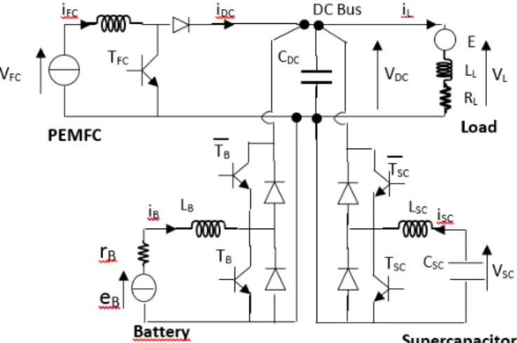
The electric system proposed here is constituted of the FC as the main source providing the mean power to the load, and storage systems composed of SC and battery. The used sources are connected in parallel architecture. In the proposed structure, each component is connected to the DC bus by using its own DC/DC converter. This topology has certain advantages, namely, independent control of storage unit currents and limitation of their dimensioning powers. With the converters connected in parallel, the architecture can still operate even if failures occur at one of the converters, increasing the reliability of the overall system. In the case of a failure of one of the converters, it is enough to bypass this one and to pass in degraded mode.
This hybridization consists to split the load power by defining the optimal power reference for each source (FC, battery and SC). The FC should give the majority of the load power at the permanent regime. The other parts of the power are given by the storage system during the transient and startup phases. The energy exchange between the sources and load (or DC bus) is ensured by using the power converters. The FC, as a primary source, is interconnected to the load by the unidirectional converter (boost converter) that maintains the DC bus voltage VDC to its reference. While, the storage
system based on battery and SC are connected to the DC bus through the current bidirectional buck/boost converters. These converters are electronically switched circuits capable of adapting the port voltage or current magnitudes to a desired value. In fact, the output voltages of the converters of the FC, the SC and the battery are then equal to the voltage of the DC bus capacitor. Fig.1 illustrates the studied structure of multisources multiconverters system. Fig.2 shows the proposed control that combines the IDA-PBC with HJB. This scheme allows to view the inputs and the outputs of the studied hybrid system.
Fig. 2. Scheme of the proposed optimal control of the FC/SCs/Batteries structure b. Modelling of the studied hybrid system
The first step is the state space mathematic representation of the hybrid system, which is given as function of the state variables. The state space representation of the traction system is proposed in (Eq.1):
𝑥̇1= 1 𝐿𝐹𝐶 [𝑉𝐹𝐶−µ1𝑥2] 𝑥̇2= 1 𝐶𝐷𝐶 [µ1𝑥1− 𝑥6+ µ2𝑥3+ µ3𝑥5] 𝑥̇3= 1 𝐿𝑆𝐶 [𝑥4−µ2𝑥2] 𝑥̇4= − 1 𝐶𝑆𝐶 𝑥3 𝑥̇5= 1 𝐿𝐵 [𝑒𝐵− 𝑟𝐵𝑥5−µ3𝑥2] 𝑥̇6= 1 𝐿𝐿 [𝑥2−𝑅𝐿𝑥6− 𝐸𝐿] (1)
From the (Eq.1), the state space representation are first order differential equations, where the overall studied system is a sixth order nonlinear system, where the state space variables are defined as:
𝑥 = [𝑥1 , 𝑥2, 𝑥3 , 𝑥4, 𝑥5, 𝑥6]𝑇 = [𝑖𝐹𝐶, 𝑉𝐷𝐶, 𝑖𝑠𝑐 , 𝑉𝑠𝑐, 𝑖𝐵, 𝑖𝐿]𝑇
Where µ = [µ1, µ2 µ3] = [1-u1, 1-u2,1-u3]
u1 , u2, u3 are respectively, the control of the FC boost converter, the control of the SC buck-boost converter and the
control of the battery buck-boost converter.
The design of the control laws by IDA-PBC follows a mathematical process, for more details, the reader can refer to the works of [43][31][34]. Regarding the chosen scenario, the equilibrium trajectories are given as
𝑥 = [𝑥̅1 , 𝑥̅2, 𝑥̅3 , 𝑥̅4, 𝑥̅5, 𝑥̅6]𝑇= [𝑥̅1 , 𝑉𝑑, 𝑥̅3 , 𝑉𝑆𝐶𝑑, 𝑥̅5,
𝑉𝑑− 𝐸𝐿
𝑅𝐿
]
𝑇
The battery SOC is given by the Coulomb Counter estimator as: 𝑆𝑂𝐶 = 𝑆𝑂𝐶0−
1 𝑄𝑛
∫ 𝑥5 𝑑𝑡
With SOC is the battery state of charge, 𝑆𝑂𝐶0 the initial battery SOC, Qn is the nominal battery capacity.
By considering the battery SOC, the battery current reference 𝑥̅5𝑆𝑂𝐶is given by:
HJB
𝑥̅5𝑆𝑂𝐶 = 𝑥̅
5∗ 𝑆𝑂𝐶
Motivation of the choice of 𝑥̅5𝑆𝑂𝐶 is the reference of the battery current. It is set at the nominal battery current in order
to be able to extract the nominal current from the battery when the battery is used. However, 𝑥̅5𝑆𝑂𝐶is the used battery
current reference, which takes into account its actual SOC. Indeed, if the SOC is full (SOC=1), one can extract the nominal battery current. As long as the battery is discharged, as long as the requested battery current reference will decrease since 𝑆𝑂𝐶 ∈ [1 − 0]. If the battery is recharged, the SOC will be increased and one can ask more current from the battery.
Thereafter, the control laws at equilibrium are defined as follows: 𝜇̅ = [𝜇̅1, 𝜇̅2, 𝜇̅3]𝑇= [ 𝑉𝐹𝐶 𝑉𝑑 , 𝑉𝑆𝐶𝑑 𝑉𝑑, 𝑒𝐵−𝑟𝐵𝑥̅5𝑆𝑂𝐶 𝑉𝑑 ] 𝑇
The closed loop desired energy function of the system is given by:
𝐻𝑑 = 1
2𝑥̃
𝑇𝑄𝑥̃ (2)
𝑥̃ = 𝑥 − 𝑥̅ represents to the difference between the state variable 𝑥 and its desired value 𝑥̅. 𝑄 = [𝐿𝐹𝐶, 𝐶𝐷𝐶, 𝐿𝑆𝐶, 𝐶𝑆𝐶, 𝐿𝐵, 𝐿𝐿]𝑇is a diagonal matrix.
The following step consists to rewrite the system equation (Eq.1) using the new variable𝑥̃, that allows obtaining the error dynamic equations.
𝑥̃̇1 = 1 𝐿𝐹𝐶 [−µ1𝑥̃2+ 𝑥̅2(𝜇̅1− 𝜇1)] 𝑥̃̇2= 1 𝐶𝐷𝐶 [µ1𝑥̃1+ µ2𝑥̃3+ µ3𝑥̃5− 𝑥̃6+ 𝑥̅1(𝜇̅1− 𝜇1) + 𝑥̅3(𝜇̅2− 𝜇2) + 𝑥̅5(𝜇̅3− 𝜇3)] 𝑥̃̇3= 1 𝐿𝑆𝐶 [−µ2𝑥2+𝑥̃4+𝑥̅4−µ2𝑥̅2] 𝑥̃̇4= − 1 𝐶𝑆𝐶 [𝑥̃3+ 𝑥̅3] 𝑥̃̇5= 1 𝐿𝐵 [−µ3𝑥̃2+ 𝑥̅2(𝜇̅3− 𝜇3) − 𝑟𝐵𝑥̃5] 𝑥̃̇6= 1 𝐿𝐿 [𝑥̃2−𝑅𝐿𝑥̃6] (3)
The error dynamic equations are expressed as follows:
𝐽(𝜇1, 𝜇2, 𝜇3) = − 𝐽𝑇(𝜇1, 𝜇2, 𝜇3) is a skew symmetric matrix defining the interconnection between the state space and
R=RT≥0 is a symmetric positive semi definite matrix defining the damping of the system.
The following control laws are suggested:
{ 𝑢1 = 𝑢̅1 𝑢2= 𝑢̅2− 𝑟𝑥̃3 𝑢3= 𝑢̅3 = 𝑒𝐵− 𝑟𝐵𝑥̅5𝑆𝑂𝐶 𝑉𝑑 (5)
where 𝑟 > 0 corresponds to a design parameter allowing to increase the damping (and consequently the rapidity) of the system.
Stability proof: with the chosen control (Eq.5), the error dynamic in closed loop is given by: 𝑥̃̇ = [𝐽(𝜇) − 𝑅′]∇𝐻𝑑 (6) With 𝑅′ = 𝑑𝑖𝑎𝑔 {0; 0; 0; 𝑟;𝑟𝐵 𝐿2𝑠𝑐; 𝑅𝐿 𝐿𝐿2} = 𝑅 ′𝑇≥ 0
The origin of the closed loop system (Eq.6) with the control laws (Eq.5) and the radially unbounded energy function (Eq.2) is globally stable.
The time derivative of the desired energy function (Eq.2) along the trajectory of (Eq.6) is: 𝐻̇𝑑= ∇𝐻𝑑𝑇𝑥̃̇ = −∇𝐻𝑑𝑇𝑅′∇𝐻𝑑≤ 0 (7)
Consequently, the derivative of the desired energy function 𝐻𝑑, which plays the role of the Lyapunov function, is non positive definite and the origin of the system given by (Eq.6) is globally stable.
4. Cost function using Hamilton-Jacobi Bellman method
In order to guarantee the operation and the requested autonomy of the hybrid electric vehicle, it is necessary to optimize the operation of the embedded sources. The optimal control is one of the methods, which treats the problem of optimization in the electric cars field. In this work, the constraints optimization of the used sources is solved by the
[𝐽 − 𝑅] ∇𝐻
resolution of the HJB equations. For this, the constraints must be formulated in the form of an optimality criterion to be solved. The optimal control is determined especially by the following steps (i) verify the initial and final conditions; (ii) satisfy several imposed constraints; (iii) optimize a selected criterion.
a. Initial and final conditions:
The terminal conditions characterize both the initial and final states after the action of control. These terminal conditions may be imposed or not.
𝑥(𝑡0) = 𝑥0 ; 𝑥(𝑡𝑓) = 𝑥𝑓 (8)
The minimization of the consumption is defined by the minimum of power that is equivalent to the minimum of the power square minP⇔minP2. For example for FC, the goal is to minimize the hydrogen consumption that involves the
minimization of the FC power.
b. Instantaneous and integral constraints:
The instantaneous constraints concern generally the physical limitations on the control or on process state. This constraint can be expressed by the following equation:
𝑞(𝑥, 𝑢, 𝑡) ≤ 0 (9)
By introducing the additional variables 𝑉2, (Eq.9) can be reduced to equality constraints as following:
𝑞(𝑥, 𝑢, 𝑡) + 𝑉2= 0 (10)
While, the integral constraints are often linked to limited resources or a limitation of the results of our actions. The following form expresses this:
∫ 𝑝(𝑥, 𝑢, 𝑡)𝑑𝑡 ≤ 0
𝑡𝑓
𝑡0
(11)
The equality integral constraints can be obtained by adding 𝑊2 terms and (Eq.11) comes as following:
∫ 𝑝(𝑥, 𝑢, 𝑡)𝑑𝑡 + 𝑊2𝑑𝑡 𝑡𝑓
𝑡0
= 0 (12)
c. Optimality criterion:
The optimality criterion can consider the following points: The initial and final values of the states,
The minimization of the final deviation from a given reference, Take into account all the state or control values at each moment. The most general form of the optimization criterion is written as:
𝐽 = 𝑔(𝑥0, 𝑡0, 𝑥𝑓, 𝑡𝑓) + ∫ Г(𝑥, 𝑢, 𝑡)𝑑𝑡 𝑡𝑓
𝑡0
(13) The main criteria used are:
- Minimum time criteria that is used in minimization problem associated with the duration.
- Quadratic criteria: used in energy minimization problem and in control problem (stabilization/motion tracking). - Consumption type criteria: concerns the production process, used to reduce operating costs and autonomous
process with limited resources to increase the operating time.
One of the method to solve optimal control problem is introducing the HJB equations.
Consider the general case of minimizing Г(𝑥, 𝑢, 𝑡)/u with dynamic constraints, ie 𝑓(𝑥, 𝑢, 𝑡). One can use a quantity called the Hamiltonian of the system, defined by:
𝐻(𝑥, 𝑢, 𝜆, 𝑡) ≜ −Г(𝑥, 𝑢, 𝑡) + 𝜆𝑇𝑓(𝑥, 𝑢, 𝑡) (14)
Г is a scalar used in the criterion to be minimized, λ is Lagrange multiplier and f characterizing the state variable equations of the system.
𝑚𝑖𝑛𝐻 ⟹ 𝑑𝐻 = 𝐻𝑥𝑑𝑥 + 𝐻𝑢𝑑𝑢 + 𝐻𝜆= 0
The canonical equations for the (Eq.14) are as following:
𝐻𝑢= 𝑟𝑢+ 𝜆𝑇𝑓𝑢= 0 (15)
𝐻𝑥 = 𝑟𝑥+ 𝜆𝑇𝑓𝑥 = −𝜆̇ (16)
𝐻𝜆= 𝑓(𝑥, 𝑢, 𝑡) = 𝑥̇ (17)
Where 𝐻𝑢, 𝐻𝑥 and 𝐻𝜆 are the partial derivation of 𝐻 regarding 𝑢, 𝑥 and 𝜆, respectively.
The optimal control u* is that minimizes the Hamiltonian, where constraints and terminal conditions being satisfied. The following paragraph presents the application of the optimal control based on HJB method for a hybrid system composed of FC, SC and battery.
The hydrogen consumption minimizing is considered as the main task for the FC optimization which is can corresponded to the minimization of the FC power and consequently the square FC power.
𝑚𝑖𝑛 𝐻 2 ⟺ min 𝑃𝐹𝐶 ⟺ min 𝑃𝐹𝐶2
Consider by (Eq.18) the cost function that allows achieving the optimal solution for the energy management of hybrid system:
𝐶 = 𝛼𝑃𝐹𝐶2 + 𝛽𝑃𝐵𝑎𝑡𝑡2 + 𝛾𝑃𝑆𝐶2 (18)
With 𝛼 + 𝛽 + 𝛾 = 1
α, β, γ are positive parameters to be chosen in order to give more importance or more use to one source out of others. Each of these parameters can take continuous value between 0 and 1.
d. Optimization criteria: 𝐽 = ∫ 𝐶 𝑑𝑡 = ∫(𝛼𝑃𝐹𝐶2 + 𝛽𝑃𝐵𝑎𝑡𝑡2 + 𝛾𝑃𝑆𝐶2) 𝑑𝑡 𝑡 0 𝑡 0 (19) e. Constraints:
It corresponds to the electric power balance of FC/SC/Battery system. The constraint equation describe the relationship between the power required to propel the vehicle, the FC power, the SC power and battery power [41]. It can be given by:
𝑓 = 𝑃𝐹𝐶 + 𝑃𝐵𝑎𝑡𝑡+ 𝑃𝑆𝐶− 𝑃𝐿= 0 (20)
f. Hamiltonian equation:
In order to express the optimal control problem as unconstrained problem, the Hamiltonian function is used [40] that links between the cost function and the constraint through Lagrange multiplier λ, as:
𝐻 = 𝐶 + 𝜆𝑇𝑓 = 𝛼𝑃
𝐹𝐶2 + 𝛽𝑃𝐵𝑎𝑡𝑡2 + 𝛾𝑃𝑆𝐶2 + 𝜆(𝑃𝐹𝐶 + 𝑃𝐵𝑎𝑡𝑡+ 𝑃𝑆𝐶− 𝑃𝐿) (21)
The optimal control theory requires that the necessary condition is given when the variation of the performance measure is zero [42] that give the canonical equations as following:
{ 𝐻𝑝𝐹𝐶 = 2𝛼𝑃𝐹𝐶∗ + 𝜆 = 0 𝐻𝑝𝐵𝑎𝑡𝑡= 2𝛽𝑃𝐵𝑎𝑡𝑡∗ + 𝜆 = 0 𝐻𝑝𝑆𝐶= 2𝛾𝑃𝑆𝐶∗ + 𝜆 = 0 𝐻𝜆= 𝑃𝐹𝐶∗ + 𝑃𝐵𝑎𝑡𝑡∗ + 𝑃𝑆𝐶∗ − 𝑃𝐿= 0 (22) The * stands in (Eq.22) for the optimal solution.
⟺ { 𝑃𝐹𝐶∗ = −𝜆 2𝛼 𝑃𝐵𝑎𝑡𝑡∗ = −𝜆 2𝛽 𝑃𝑆𝐶∗ =−𝜆 2𝛾 𝑃𝐹𝐶∗ + 𝑃𝐵𝑎𝑡𝑡∗ + 𝑃𝑆𝐶∗ = 𝑃𝐿 (23)
After a simple calculation, the solution is: 𝜆 = −𝑃𝐿 2𝛼𝛽𝛾 𝛽𝛾 + 𝛼𝛾 + 𝛼𝛽 (24) ⟺ { 𝑃𝐹𝐶∗ = 𝛽𝛾 𝛽𝛾 + 𝛼𝛾 + 𝛼𝛽𝑃𝐿 𝑃𝐵𝑎𝑡𝑡∗ = 𝛼𝛾 𝛽𝛾 + 𝛼𝛾 + 𝛼𝛽𝑃𝐿 𝑃𝑆𝐶∗ = 𝛼𝛽 𝛽𝛾 + 𝛼𝛾 + 𝛼𝛽𝑃𝐿 𝑃𝐹𝐶∗ + 𝑃𝐵𝑎𝑡𝑡∗ + 𝑃𝑆𝐶∗ = 𝑃𝐿 (25) 𝑃𝐵𝑎𝑡𝑡∗ = 𝑉𝐵𝑎𝑡𝑡∗ ∙ 𝐼𝐵𝑎𝑡𝑡∗ 𝑃𝑆𝐶∗ = 𝑉𝑆𝐶∗ ∙ 𝐼𝑆𝐶∗ (26) 𝐼𝐵𝑎𝑡𝑡∗ = 𝛼𝛾 𝛽𝛾 + 𝛼𝛾 + 𝛼𝛽 𝑃𝐿 𝑉𝐵 𝐼𝑆𝐶∗ = 𝛼𝛽 𝛽𝛾 + 𝛼𝛾 + 𝛼𝛽 𝑃𝐿 𝑉𝑆𝐶 (27) 𝐼𝐵𝑎𝑡𝑡∗ is the optimal battery reference that will play the role of 𝑥̅5 in our IDA-PBC control.
The optimal battery and SC references calculated by HJB are as function of the actual load power, battery and SC voltage. The prior knowledge of the road profile is not necessary.
5. Experimental setup
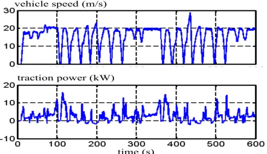
Experiments were carried out at the IRH (Institue de Recherche sur l’Hydrogène) at Trois Rivière University, Canada. In this study, the FC/SC/Battery electric vehicle is emulated by using a dynamic power with reduction of the Nemo vehicle scale (see Fig.3, as proposed in [35]). Consequently, the used test bench does not pretend to the vehicle sizing but to the validation of the portability in real time of the proposed control and the energy management by considering source limitations.
vehicle speed (m/s)
traction power (kW)
time (s)
Fig. 3. Speed (top) and power (down) of the Nemo vehicle from an on road test drive
The experimentations have been performed in order to evaluate the effectiveness of the proposed control and to see the integrated system under work. The Fig.4 illustrates the picture of the used test bench for the experimental implementation in this study. As shown in the experimental platform (Fig.4), the used components are:
- Three adjustable DC/DC converters; - DC bus capacitor;
- Horizon PEMFC;
- Three lead acid battery connected in series - Two modules of Maxwell SC
- Programmable DC load - Acquisition data
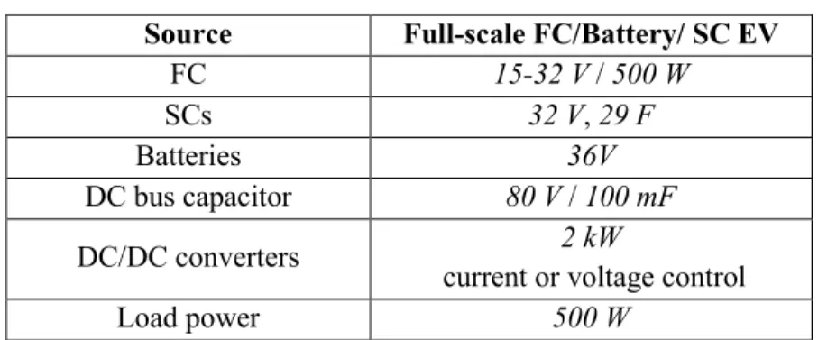
The parameters of used components in test bench are given in Table.1 (See appendix).
The FC/SC/Battery architecture is presented experimentally, where the FC provides the positive power, while the SC provides the necessary dynamic to the traction of the vehicle and absorbs excess of power. However, the batteries help the FC to satisfy the demanded load. Consequently, the FC is subject the moderate stress thanks to the used auxiliary sources (batteries and SC).
Fig. 4. Picture of the used test bench.
Converters
Batteries PEMFCSCs
Bus
DC
Load
Acquisition system6. Experimental result and discussion
The experimental results demonstrate that passivity based control is adapted in real time, given the good and rapid performance of the current and voltage tracking and provides the stability proof of the system.
Fig.5. FC current Fig.6. FC voltage
Fig.5 and Fig.6 present the electrical responses of FC, IFC, VFC, respectively. These curves show the slow dynamic of
the FC source and the FC provide the energy at permanent phases.
Fig.7. IBatt and I_Batt ref obtained from HJB method Fig.8. Battery voltage
The battery electrical behavior is provided on Fig.7 and Fig.8 as current and voltage, respectively. Fig.7 illustrates that battery current follows exactly its reference (obtained from HJB method) with error around ±0.5 A. In other hand, this figure shows that the battery is solicited only in steady state at t = 114s – 127s to help the FC to supply the load and it is used amongst other to charge the SC. The battery voltage in Fig.8 shows that the battery is practically fully charged (~97%) from 0s to 114s, its voltage decreases until 33.5V to charge the SC and at same time compensates the difference between the load demanded power and the provided power by the FC.
In Fig.9, the SC current and its desired trajectory (obtained from HJB) are presented, and one can see that SC current tracks exactly its reference at all time during this cycle. The Fig.10 presents the voltage of SC as function of the time; the SC possesses the initial output voltage of 24 V and the voltage at the end of the cycle of 24V. When the SC will be discharged, it can be charged again by the FC and/or battery.
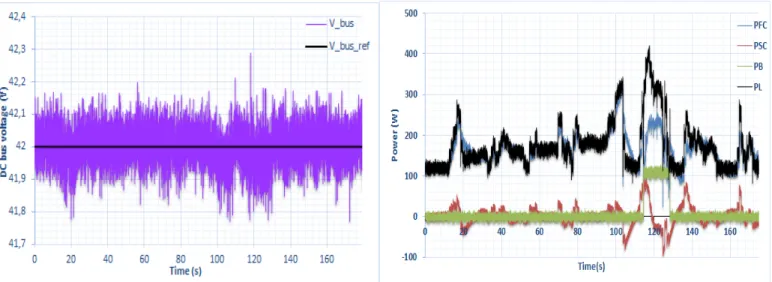
Fig.11. DC bus voltage and its reference
The DC bus voltage and its reference are illustrated in Fig.11. From this later, the DC bus voltage is controlled at 42V. The proposed control manages efficiently the energy to maintain the DC bus voltage constant at 42 V. The DC bus voltage follows quite good its reference; even if this voltage of bus fluctuates but in an acceptable range of static error around of ±0.2V that can be caused by the measurement noise in the real system. Fig.12 presents the significant result of the used source powers as function of time and that shows the role of each embedded source in the studied hybrid system. In other hand, the Fig.12 illustrates that the proposed control manages correctly the energy between the sources and that the hybrid system can satisfy the demanded energy in different regimes in real time with instantaneous response. From this figure, one can note that at all time, the sum of the used source powers is equal to the load power. In addition, it is clear that the FC satisfies the load power demand in the steady state. The FC source does not go up or down too steeply. The FC power is always positive. While the SC follows the behavior of the load power. The SC takes in charge the transient phases. However, the battery can compensate the difference between the demanded power by the traction
Fig. 9. Experimentally results of ISC and 𝐼𝑆𝐶∗ obtained from
HJB method Fig.10. SC voltage obtained experimentally
Fig. 12. Experimental results of power distribution of the different sources
and the provided power by the FC at steady state, as shown in Fig.12 at t= 113s. Therefore, the battery can help the FC to satisfy the load demand.
In general case, the particularly attention is paid on the power distribution and the DC bus voltage regulation. 7. Conclusion
Through this study, the optimal control and the energy management of DC hybrid sources have been presented. The system complexity due to the system nonlinearity and to the source limitations makes it difficult to find the control that optimally dispatches the power flow between sources and load and at the same time providing the global stability proof. Our contribution consists on a new combination of the nonlinear IDA-PBC (Interconnection and Damping Assignment-Passivity Based Control) approach with HJB (Hamilton Jacobi Bellman) optimization method to manage and control a multisources multiconverters hybrid system for electrical vehicle. The HJB optimization is used for the generation of the desired optimal reference trajectories for each sources taking into consideration the limitation constraints of the embedded source. The IDA-PBC technic is used to control the power sharing between sources and to ensure the auxiliary sources current/voltage tracking to their references. The experimental validation considering the battery limitations has been performed and validates the effectiveness of the proposed combination in terms of the stability, the optimal energy management, good performance of tracking and application in real time.
Appendix:
Table 1. Hybrid electrical vehicle parameters
References
[1] Y. Jingni, Y. Lin, and C. Qu, “Intelligent energy management strategy based on hierarchical approximate global optimization for plug-in fuel cell hybrid electric vehicles,” Int. J. Hydrogen Energy, vol. 43, no. 16, pp. 8063– 8078, 2018.
[2] L. Ming, Y. Ying, L. Liang, L. Yao, and W. Zhou, “Energy Management Strategy of a Plug-in Parallel Hybrid Electric Vehicle Using Fuzzy Control,” Energy Procedia, vol. 105, pp. 2660–2665, 2017.
[3] N. Arina and T. Adriana, “Opacity Analysis and Estimation of CO 2 Exhausted by a Diesel Engine Vehicle Running under Urban Traffic Conditions Faculty of Civil Engineering,” WSEAS Trans. HEAT MASS Transf., vol. 7, no. 2, pp. 27–36, 2012.
[4] M. Hilairet, M. Ghanes, O. Béthoux, V. Tanasa, J.-P. Barbot, and D. Normand-Cyrot, “A passivity-based controller for coordination of converters in a fuel cell system,” Control Eng. Pract., vol. 21, no. 8, pp. 1097– 1109, Aug. 2013.
[5] J. Zhao, P. Chen, U. Ibrahim, and J. Wang, “Comparative Study and Accommodation of Biodiesel in Diesel‐ Electric Hybrid Vehicles Coupled with Aftertreatment Systems,” Asian J. Control, vol. 18, no. 1, 2015.
[6] H. R. Karimi, J. Xi, and F. Yan, “Special Issue on “Recent Developments on Modeling and Control of Hybrid Electric Vehicles,” Asian J. Control, vol. 18, no. 1, 2016.
[7] A. Khaligh, S. Member, and Z. Li, “Battery , Ultracapacitor , Fuel Cell , and Hybrid Energy Storage Systems for Electric , Hybrid Electric , Fuel Cell , and Plug-In Hybrid Electric Vehicles : State of the Art,” IEEE Trans. Veh. Technol., vol. 59, no. 6, pp. 2806–2814, 2010.
Source Full-scale FC/Battery/ SC EV
FC 15-32 V / 500 W
SCs 32 V, 29 F
Batteries 36V
DC bus capacitor 80 V / 100 mF
DC/DC converters 2 kW
current or voltage control
[8] A. Tabanjat, M. Becherif, D. Hissel, and H. S. Ramadan, “Energy management hypothesis for hybrid power system of H2/WT/PV/GMT via AI techniques,” Int. J. Hydrogen Energy, vol. 43, pp. 3527–3541, 2018. [9] A. Benmouna, M. Becherif, D. Depernet, and F. Gustin, “Fault diagnosis methods for proton exchange
membrane fuel,” Int. J. Hydrogen Energy, vol. 42, no. 2, pp. 1534–1543, 2017.
[10] Z. Mokrani, D. Rekioua, N. Mebarki, T. Rekioua, and S. Bacha, “Proposed energy management strategy in electric vehicle for recovering power excess produced by fuel cells,” Int. J. Hydrogen Energy, vol. 42, no. 30, pp. 19556–19575, 2017.
[11] Z. Song, J. Li, J. Hou, H. Hofmann, M. Ouyang, and J. Du, “The Battery-Supercapacitor Hybrid Energy Storage System in Electric Vehicle Applications : A Case Study,” Energy, 2018.
[12] X. Zhang, L. Liu, Y. Dai, and T. Lu, “Experimental investigation on the online fuzzy energy management of hybrid fuel cell/battery power system for UAVs,” Int. J. Hydrogen Energy, vol. 43, no. 21, pp. 10094–10103, 2018.
[13] C. Musardo, G. Rizzoni, Y. Guezennec, and B. Staccia, “A-ECMS: An Adaptive Algorithm for Hybrid Electric Vehicle Energy Management,” Eur. J. Control, vol. 11, no. 4–5, pp. 509–524, 2005.
[14] N. Kim, S. Ha, J. Jeong, and S. W. Cha, “Sufficient conditions for optimal energy management strategies of fuel cell hybrid electric vehicles based on Pontryagin’s minimum principle,” Proc. Inst. Mech. Eng. Part D J. Automob. Eng., 2015.
[15] V. Tejwani and B. Suthar, “Power management in fuel cell based hybrid systems,” Int. J. Hydrogen Energy, vol. 42, no. 22, pp. 14980–14989, 2017.
[16] A. Benmouna, M. Becherif, D. Depernet, and M. A. Ebrahim, “Novel Energy Management Technique for Hybrid Electric Vehicle via Interconnection and Damping Assignment Passivity Based Control,” Renew. Energy, vol. 119, pp. 116–128, 2018.
[17] N. Marx, D. Hissel, F. Ed, E. Gustin, L. Boulon, and K. Agbossou, “On the sizing and energy management of an hybrid multistack fuel cell e Battery system for automotive applications,” Int. J. Hydrogen Energy, vol. 42, pp. 1518–1526, 2017.
[18] B. Vural et al., “Fuel cell and ultra-capacitor hybridization: A prototype test bench based analysis of different energy management strategies for vehicular applications,” Int. J. Hydrogen Energy, vol. 35, no. 20, pp. 11161– 11171, 2010.
[19] M. Mohammedi, M. Becherif, A. Aboubou, O. Kraa, M. Y. Ayad, and M. Bahri, “Fuzzy Logic and Passivity Based Control applied to Hybrid DC Power Source using Fuel Cell and Battery,” in Proceedings of the 4th International Conference on Systems and Control, Sousse, Tunisia, April 28-30, 2015, 2015, pp. 510–515. [20] Q. Li, T. Wang, C. Dai, W. Chen, and L. Ma, “Power Management Strategy based on Adaptive Droop Control
for a Fuel Cell-Battery-Supercapacitor Hybrid Tramway,” IEEE Trans. Veh. Technol., vol. 9545, no. c, 2017. [21] C. Zhao, H. Yin, and C. Ma, “Two-level energy management strategy for a fuel cell-battery-ultracapacitor hybrid
system,” in IECON Proceedings (Industrial Electronics Conference), 2016.
[22] Z. Hong, Q. Li, Y. Han, W. Shang, Y. Zhu, and W. Chen, “An energy management strategy based on dynamic power factor for fuel cell/battery hybrid locomotive,” Int. J. Hydrogen Energy, vol. 43, no. 6, pp. 3261–3272, 2018.
[23] Z. Lei, D. Cheng, Y. Liu, D. Qin, Y. Zhang, and Q. Xie, “A dynamic control strategy for hybrid electric vehicles based on parameter optimization for multiple driving cycles and driving pattern recognition,” Energies, vol. 10, no. 1, 2017.
[24] P. M. Muñoz, G. Correa, M. E. Gaudiano, and D. Fernández, “Energy management control design for fuel cell hybrid electric vehicles using neural networks,” Int. J. Hydrogen Energy, vol. 42, no. 48, pp. 28932–28944, 2017.
[25] N. Sulaiman, M. A. Hannan, A. Mohamed, E. H. Majlan, and W. R. Wan Daud, “A review on energy management system for fuel cell hybrid electric vehicle: Issues and challenges,” Renew. Sustain. Energy Rev., vol. 52, pp. 802–814, 2015.
[26] M. Mordjaoui, S. Haddad, A. Medoued, and A. Laouafi, “Electric load forecasting by using dynamic neural network,” Int. J. Hydrogen Energy, vol. 42, no. 28, pp. 17655–17663, 2017.
[27] H. Aouzellag, K. Ghedamsi, and D. Aouzellag, “Energy management and fault tolerant control strategies for fuel cell/ultra-capacitor hybrid electric vehicles to enhance autonomy, efficiency and life time of the fuel cell system,” Int. J. Hydrogen Energy, vol. 40, no. 22, pp. 7204–7213, 2015.
[28] H. Hemi, J. Ghouili, and A. Cheriti, “Combination of Markov chain and optimal control solved by Pontryagin’s Minimum Principle for a fuel cell / supercapacitor vehicle,” Energy Convers. Manag., vol. 91, pp. 387–393,
2015.
[29] O. Kraa, H. Ghodbane, M. Y. Ayad, M. Becherif, A. Aboubou, and M. Bahri, “Energy Management of Fuel Cell/ Supercapacitor Hybrid Source Based on Linear and Sliding Mode Control,” Energy Procedia, vol. 74, no. 0, pp. 1258–1264, 2015.
[30] M. Y. Ayad, M. Becherif, A. Henni, A. Aboubou, M. Wack, and S. Laghrouche, “Passivity-Based Control applied to DC hybrid power source using fuel cell and supercapacitors,” Energy Convers. Manag., vol. 51, no. 7, pp. 1468–1475, 2010.
[31] R. Ortega and E. Garcıá-Canseco, “Interconnection and Damping Assignment Passivity-Based Control: A Survey,” Eur. J. Control, vol. 10, no. February, pp. 432–450, 2004.
[32] A. Benmouna, M. Becherif, C. Dépature, L. Boulon, and D. Depernet, “Experimental study of energy management of FC/SC hybrid system using the Passivity Based Control,” Int. J. Hydrogen Energy, vol. 3, pp. 1–10, 2018.
[33] M. Mohammedi, O. Kraa, M. Becherif, A. Aboubou, M. Y. Ayad, and M. Bahri, “Fuzzy logic and passivity-based controller applied to electric vehicle using fuel cell and supercapacitors hybrid source,” Energy Procedia, vol. 50, no. 0, pp. 619–626, 2014.
[34] M. Becherif, “Passivity-based control of hybrid sources: Fuel cell and battery,” IFAC Proc. Vol., vol. 11, no. PART 1, pp. 585–590, 2006.
[35] M. Hilairet, O. Béthoux, M. Ghanes, V. Tanasa, J. P. Barbot, and M. D. Normand-Cyrot, “Experimental validation of a sampled-data passivity-based controller for coordination of converters in a fuel cell system,” IEEE Trans. Ind. Electron., vol. 62, no. 8, pp. 5187–5194, 2015.
[36] R. Ortega, A. van der Schaft, B. Maschke, and G. Escobar, “Interconnection and damping assignment passivity-based control of port-controlled Hamiltonian systems,” Automatica, vol. 38, no. 4, pp. 585–596, 2002.
[37] R. Ortega, F. Member, and A. Sasongko, “Energy Management of Fuel Cell / Battery / Supercapacitor Hybrid Power Sources Using Model Predictive Control,” vol. 10, no. 4, pp. 1992–2002, 2014.
[38] S. I. Seleme, L. M. F. Morais, A. H. R. Rosa, and L. A. B. Torres, “Stability in passivity-based boost converter controller for power factor correction,” Eur. J. Control, vol. 19, no. 1, pp. 56–64, 2013.
[39] A. Behdani and M. Naseh, “Power management and nonlinear control of a fuel cell–supercapacitor hybrid automotive vehicle with working condition algorithm,” Int. J. Hydrogen Energy, vol. 2, 2017.
[40] J. Zhu, “A feedback optimal control by Hamilton-Jacobi-Bellman equation,” Eur. J. Control, vol. 37, pp. 70– 74, 2017.
[41] M. Becherif and E. Mendes, “Stability And Robustness Of Disturbed-Port Controlled Hamiltonian Systems With Dissipation,” IFAC Proc. Vol., vol. 38, no. 1, pp. 574–579, Jan. 2005.