HAL Id: tel-03217124
https://tel.archives-ouvertes.fr/tel-03217124
Submitted on 4 May 2021HAL is a multi-disciplinary open access
archive for the deposit and dissemination of sci-entific research documents, whether they are pub-lished or not. The documents may come from teaching and research institutions in France or abroad, or from public or private research centers.
L’archive ouverte pluridisciplinaire HAL, est destinée au dépôt et à la diffusion de documents scientifiques de niveau recherche, publiés ou non, émanant des établissements d’enseignement et de recherche français ou étrangers, des laboratoires publics ou privés.
synthetic and natural fibre composites for structural and
morphing applications
Guillaume Chabaud
To cite this version:
Guillaume Chabaud. 3D and 4D printing of high performance continuous synthetic and natural fibre composites for structural and morphing applications. Materials. Université de Bretagne Sud, 2020. English. �NNT : 2020LORIS563�. �tel-03217124�
L'UNIVERSITE
DE
BRETAGNE
SUD
ECOLE DOCTORALE N°602
Sciences pour l'Ingénieur
Spécialité : « Génie des matériaux » Par
Guillaume CHABAUD
3D and 4D printing of high-performance continuous synthetic and
natural fiber composites for structural applications and morphing.
Impression 3D et 4D de composites à hautes performances renforcés par des
fibres continues synthétiques ou naturelles pour des applications structurelles ou
de morphing.
Thèse présentée et soutenue à Lorient, le 16 Octobre 2020 Unité de recherche : IRDL UMR CNRS 6027
Thèse n°563
Rapporteurs avant soutenance :
Nadia Bahlouli, Professeur, Icube Université de Strasbourg Masahito Ueda, Associate-professor, Nihon University Tokyo Composition du Jury :
Président : Yves Grohens Professeur, IRDL, Université Bretagne Sud Examinateurs : Nadia Bahlouli Professeur, Icube Université de Strasbourg
Amandine Celino Maître de Conférences, GeM, Université de Nantes Fabrizio Scarpa Professor, ACCIS, University of Bristol (UK)
Jérémie Soulestin Professeur, IMT Lille Douai
Masahito Ueda Associate-professor, Nihon University Tokyo (JP) Dir. de thèse : Antoine Le Duigou Maître de Conférences-HDR, Université Bretagne Sud Co-dir. de thèse : Mickaël Castro Maître de Conférences, Université Bretagne Sud
Remerciements
En tout premier lieu, je souhaite remercier chaleureusement mes directeurs de thèse, Antoine Le Duigou et Mickaël Castro, sans qui cette thèse n’aurait pas été possible. Merci de m’avoir encadré durant ces trois ans, merci pour votre aide et votre soutien !
Un grand merci à Nadia Bahlouli, Amandine Celino, Yves Grohens et Jérémie Soulestin d’avoir accepté d’être membres du jury. Many thanks as well to Fabrizio Scarpa and Masahito Ueda for agreeing to be part of my jury.
Je remercie également les membres de l’IRDL pour leur aide et leur disponibilité, notamment Antoine Kervoelen, Françoise Peresse, Hervé Bellegou, William Berckmans, Edouard Gheslain, Anthony Magueresse, Thomas Pierre, Thibault Colinart, Vincent Keryvin, Samuel Réquilé, Camille Goudenhooft, ainsi qu’au reste de l’équipe de l’IRDL pour leurs nombreux conseils et aides apportés tout au cours de ma thèse.
Je remercie les différentes personnes de ComposiTIC et Irma pour leur accueil, leur aide technique et scientifique tout au long de ma thèse, notamment Romain Bevan, Antoine Barbé, Kevin Henry, Clément Denoual, Yves-Marie Corre, Morgane Deroiné ainsi que toutes les autres personnes de IRMAtech et ComposiTIC.
Je remercie également Mael Arhant et Peter Davies pour leur accueil au sein de l’Ifremer de Brest ainsi que de leurs contributions au cours de ces travaux.
Je souhaite également remercier les membres du jury du concours SAMPE France, Philippe Briant, Charlotte Salaun et Jérome Brouard de m’avoir donné l’opportunité de participer au SAMPE Europe, ce qui fut une expérience très enrichissante.
Je remercie également l’ensemble des doctorants de l’Université Bretagne Sud, plus particulièrement mes collègues de bureau Victor, Lucile, Delphin, Samuel et Camille, pour la bonne humeur toujours de mise et les bons moments passés dans le cadre du travail ou en dehors.
Enfin, un grand merci à ma famille et mes amis pour vos encouragements et votre soutien durant ces trois ans malgré la distance, vos visites en Bretagne et également, parfois, vos conseils.
Scientific contributions
Contests:
Second position at the French SAMPE Chapter, selection for the International Students Seminar Chapter, SAMPE Europe 2019
Participation at the 34th International Students Seminar, SAMPE Europe 2019
Accepted publications:
G. Chabaud, M. Castro, C. Denoual, A. Le Duigou, “Hygromechanical properties of 3D printed continuous carbon and glass fibre reinforced polyamide composite for outdoor structural applications,” Additive Manufacturing., vol. 26, pp. 94–105, 2019.
DOI: ttps://doi.org/10.1016/j.addma.2019.01.005
A. Le Duigou, G. Chabaud, F. Scarpa, M. Castro, “Bioinspired Electro-Thermo-Hygro Reversible Shape-Changing Materials by 4D Printing,” Advanced Functional Materials., vol. 29, pp. 1–10, 2019. DOI: https://doi.org/10.1002/adfm.201903280
Publications under review:
A.Le Duigou, G.Chabaud, R.Matsuzaki, M.Castro, “Tailoring the mechanical properties of 3D printed continuous flax/PLA biocomposites by controlling the slicing parameters”, Composites Part B, 2020.
International conferences:
G.Chabaud, M.Castro, A.Le Duigou, “3D and 4D printing of continuous carbon fiber composites: from structural applications to morphing structures”, SAMPE Europe 2019, 2019 (poster).
National conferences:
G.Chabaud, M.Castro, A.Le Duigou, “Impression 3D et 4D de matériaux composites à fibres de carbone continues : des applications structurelles au morphing de structures”, 21ème édition des Journées Nationales sur les Composites, 2019.
G.Chabaud, M.Castro, A.Le Duigou, “Impression 4D de matériaux composites multi-stimulables pour le morphing de structures”, 24ème édition du Congrès Français de Mécanique », 2019.
Table of contents
Glossary
General introduction
... 1Chapter 1: State of the art in 3D/4D printing of continuous
fiber-reinforced (bio)composites: achievements and future outlooks
... 101.
General presentation of 3D printing and Fused Filament Fabrication
... 121.1. Principle of 3D Printing ... 12
1.2. Glossary and definitions of 3D printing ... 13
2.
Overview of current research on 3D printing of thermoplastic materials
with Fused Filament Fabrication (FFF)
... 152.1. Presentation of FFF process for pure thermoplastics and current limitations .. 15
2.2. Parametric studies on 3D printed parts for the improvement of mechanical properties ... 17
2.2.1. Influence of printing parameters ... 18
2.2.2. Influence of slicing parameters ... 20
3.
3D printing of fiber reinforced composite materials
... 223.1. 3D printing of discontinuous fiber-reinforced composites ... 23
3.2. 3D printing of continuous fiber reinforced composites ... 28
3.2.1. Overview of the mechanical characterization of 3D printed continuous fiber reinforced composites ... 33
3.2.2. Current limitations in 3D printing of continuous fiber composites ... 41
3.2.3. Future outlook on the optimization of 3D printing of continuous fiber reinforced composites ... 43
4.
4D Printing of synthetic materials
... 504.1. 4D printing of polymer and composite materials ... 52
4.2. Humidity as a motor of actuation ... 60
4.3. Future outlook on the optimization of 4D printing of fiber reinforced composites ... 63
5.
3D and 4D printing of natural fiber reinforced composites
... 685.1. Natural fiber specificities for 3D printing ... 68
5.2. Filament production ... 71
5.3. 3D printing of natural fiber composites ... 72
5.4. Future outlook on the optimization of 3D printing of natural fiber reinforced composites ... 76
5.5. 4D printing of natural fiber reinforced composites ... 78
5.6. Future outlook on the optimization of 4D printing hygromorphic (bio)composites ... 84
Chapter 2: Materials and Methods
... 901.
Material selection
... 911.1. Synthetic continuous fiber reinforced composites ... 91
1.2. Flax continuous fiber reinforced biopolymer composites ... 91
2.
Manufacturing by 3D printing
... 922.1. Synthetic continuous fiber composites ... 92
2.2. Printing of continuous flax fiber reinforced composites ... 94
3.
Mechanical characterization
... 953.1. Tensile tests on single fiber and composites ... 95
3.1.1. Tensile tests on synthetic fiber ... 95
3.1.2. Tensile tests on synthetic-fiber reinforced composites ... 95
3.1.3. Tensile tests on flax-fiber reinforced composites ... 96
3.2. Characterization of interlaminar properties of synthetic continuous fiber composites ... 97
3.3. Three-point bending characterization ... 99
4.
Analysis of the microstructure
... 1004.1. Optical microscopy ... 100
4.2. Scanning Electron Microscopy (SEM) ... 100
5.
Hygroscopic conditions and seawater aging
... 1005.1. Specimen storage in various humidity chambers ... 100
5.2. Seawater-aging of 3D printed composites ... 101
5.3. Moisture sorption measurement ... 101
5.4. Hygro-expansion measurement... 101
6.
Measurement of the actuation of hygromorphic composites based on
continuous carbon fiber and continuous flax fibers, and
electro-thermo-hygromorphic composites based on continuous carbon fiber.
... 1026.1. Description of the environmental conditions for actuation ... 102
6.2. Electrical stimulus generation... 102
6.3. Measurement of the actuator curvature ... 103
7.
Thermal characterization of the composites
... 1047.1. Differential Scanning Calorimetry (DSC) ... 104
7.2. Thermogravimetric analysis (TGA) ... 104
7.3. Thermal expansion measurement ... 104
Chapter 3: Mechanical and hygromechanical properties of
continuous carbon and glass fiber composites
... 1051.
Microstructure description
... 1071.1. Filament microstructure description ... 107
1.2. Cross-section description ... 107
1.3. In-plane description ... 111
2.
Mechanical characterization
... 1142.2. Evaluation of interlaminar properties with Double Cantilever Beam (DCB) tests. 118
2.2.1. Mode I delamination resistance behavior ... 119 2.2.2. Comparison of critical strain energy release rates with literature values
121
3.
Evolution of mechanical performances under exposure to wet
environment and accelerated seawater aging
... 1243.1. Sorption behavior and hygroscopic expansion ... 124 3.1.1. Moisture uptake and hygroscopic expansion in humid environment 124 3.1.2. Evolution of water uptake and hygroscopic expansion during seawater aging 127
3.2. Evolution of tensile behavior under different moisture conditions ... 130 3.3. Influence of seawater aging on flexural properties of 3D printed composites 133
Conclusion
... 137Chapter 4: Bio-inspired reversible electro-thermo-hygro reversible
shape-changing materials by 4D printing
... 1401.
Concept of 4D printed electro-thermo-hygromorphic structural
composite materials
... 1422.
cCF/PA6-I:PA6 bilayers as hygromorphic actuators
... 1453.
cCF/PA6-I:PA6 bilayers as electro-thermo-hygromorphic actuators
... 1484.
Influence of the print pattern on the electro-thermo-hygro actuation of
the cCF/PA6-I:PA6 bilayers
... 154 4.1. Influence of the printed pattern on the electro-heating ... 156 4.2. Influence of the printed pattern on the electro-thermo-hygromorphic actuation159
Conclusion
... 165Chapter 5: Tailoring the mechanical properties of 3D printed
continuous flax/PLA biocomposites with slicing parameters
... 1671.
Production of continuous filaments of flax/PLA biocomposites and
description of the microstructure
... 169 1.1. Production of continuous filament of flax/PLA biocomposites by co-extrusion process ... 169 1.2. Microstructure of the continuous filament of flax/PLA biocomposites prior to printing ... 1702.
Influence of Layer Height (LH) on the mechanical properties of printed
cFF/PLA composites
... 1713.
Influence of Trip Number (TN) and Interfilament Distance (ID) on the
mechanical properties of printed cFF/PLA composites
... 1754.
Influence of Layer Number (LN) on the mechanical properties of printed
5.
Influence of raster angle / fiber orientation on the mechanical properties
of printed cFF/PLA composites
... 185Conclusion
... 188Chapter 6: 4D printing of hygromorphic biocomposites with
continuous flax fiber/PLA: toward compliant mechanism
... 1901.
Design of hygromorphic biocomposites
... 1922.
Material selection
... 1953.
Control of the stiffness with variation of the architecture by controlling
the interfilament distance
... 2004.
Compliant mechanism with localized bending actuation
... 204Conclusion
... 207General conclusion
... 209Perspectives
... 213Glossary
µ-CT Micro-computed Tomography MCC Modified Compliance Calibration
ABS Acrylonitrile Butyadiene Styren MFR Mass Flow Rate
AFP Automated Fiber Placement NASA National Aeronautics and Space Administration
ASTM American Society for Testing and Materials NFC Natural Fiber Cellulose
ATL Automated Tape Laying P2VP Poly(2-vinylpyridine)
BAAM Big Area Additive Manufacturing PA Polyamide
BOPP Biaxially Oriented PolyPropylene PA6-I Polyhexamethylene isophtalamide
CAD Computer Aided Design PAAM Poly(acrylic acid co-acrylamide)
CBT Corrected Beam Theory PBS Polybutylene Succinate
cCF/PA6-I
3D printed continuous carbon fiber
polyhexamethylene isophtalamide matrix PC Polycarbonate
cFF/PBS 3D printed continuous flax fiber
polybutylene succinate matrix PCL Poly(ε-caprolactone)
cFF/PLA 3D printed continuous carbon fiber
polylactic acid atrix PEDOT:PSS
Poly(3,4-ethylenedioxythiophene):poly(styrenesulfonic acid)
cGF/PA6 3D printed continuous carbon fiber PA6-I
matrix PEEK Poly-ether-ether-ketone
CHE Coefficient of Hygroscopic Expansion PEGDA Poly(ethylene glycol) diacrylate
CMC CarboxyMethyl Cellulose PEKK Poly-ether-ketone-ketone
MFA MicroFibril Angle PETG Polyethylene glycol
CTE Coefficient of Thermal Expansion PHA Polyhydroxylalcanoate
DCB Double Cantilever Beam PLA Polylactic acid
DSC Differential Scanning Calorimetry PNIPAm Poly(acryl acid-co-N-isopropyl acrylamide)
EBM Electron Beam Melting POM Polyoxymethylene
FDM Fused Deposition Modeling RH Relative Humidity
FFF Fused Filament Fabrication ROM Rule Of Mixture
GIC Critical Energy Strain Rate SEM Scanning Electron Microscopy
HBC Hygromorphic Biocomposites SLA Stereolithography
HEPA Hygroexpansive Electrothermal Paper
Actuators SLS Selective Laser Sintering
ID Interfilament Distance SMC Shape Memory Composites
IFSS InterFacial Shear Strength SME Shape Memory Effect
ILSS InterLaminar Shear Strength SMP Shape Memory Polymer
ISO International Organization for
Standardization STL Standard Tessellation Language
LCA Life Cycle Analysis TCP Toner Coated Paper
LCE Liquid Crystal Elastomer TGA Thermogravimetric Analysis
LH Layer Height TN Trip Number
LN Layer Number TPU Thermoplastic Polyurethane
LOM Laminated Object Manufacturing VAS Volume Average Stiffness
General introduction
The concept of additive manufacturing refers to technologies that aim to produce three-dimensional objects with the addition of matter layer-by-layer. Additive manufacturing is a promising technology that allows precise control of the trajectory of deposition and thus the architecture and properties of the materials. This concept is opposed to “subtractive manufacturing” where matter is removed from an object to create the desired shape (for example: milling, drilling, slitting...).
Automation of composite manufacturing is a great challenge, but not so new, as the Automated Fiber Placement (AFP) and the Automated Tape Laying (ATL) technologies have been widely used in aeronautic sector since the late 1980s. These technologies allow the placement of tapes (from 3 to 100 mm) to efficiently build custom laminates, layer-by-layer, with planar or curved geometry. ATL systems are normally mounted on horizontal gantries or vertical columns because of the high mass of the head. ATL systems follow accurately predefined trajectories with good reproducibility, thus eliminating layup errors that could occur during manual laying. However, this process is limited to a simple design with small variations in curvature. The AFP technology aims at laying down fibers tapes on the surface of a mold thanks to a robotic head with 7 or 8 mobile axis and allows to manufacture structures with more complex shapes than ATL. However, these technologies are restrained to a large scale with a minimum tape length of 100 mm and is prohibitively costly which limits their applications to industrial fields.
The 3D printing process is a generic branch of additive manufacturing and aims to build a three-dimensional object from a computer-aided design (CAD) model layer-by-layer under computer control. 3D printing was born in 1986 when Chuck Hull issued the patent “Apparatus for production of three-dimensional objects of stereolithography” and commercialized the first 3D printing device called SLA-250. In 1988, another 3D printing method was patented by Scott Crump and commercialized by Stratasys in 1992. This process is trademarked under the name Fused Deposition Modeling (FDM), also called Fused Filament Fabrication (FFF). This technology is based on the melting of a thermoplastic filament through to a heated nozzle and the layer-by-layer deposition of the molten polymer. Nowadays, this process has become the most widely spread 3D printing technique thanks to its easy use and the low cost of FFF 3D printers compared to other techniques such stereolithography (SLA), selective laser sintering (SLS), inkjet printing; selective laser melting (SLM), electron beam melting (EBM), laminated object manufacturing (LOM), etc…
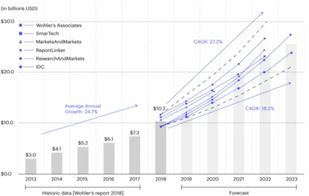
During the last decades, 3D printing has overcome many innovations regarding the material availability and the improvement of technical performances (accuracy, reproducibility, process speed…). Between years 2000 and 2010, initiation of the Reprap project at the university of Bristol (UK) and the expiration of FDM patent from Stratasys® led to large open-source movement that significantly reduced costs. The RepRap (Replicating Rapid prototypes) project is an initiative that aims to develop open source 3D printers capable of printing most of its own to enable the democratization of 3D printing technology by FFF. All these features allow 3D printing to spread for private consumers and companies. According to a report published by the International Data Corporation (IDC) in January 2019, global spending on 3D printing (materials, hardware, software and services) estimated that 3D printing market may reach $13.8 billion in 2019 and $22.7 billion in 2024 with an annual growth rate of 19.1 %. 3D printing market size forecast in the five years according to various analysists is displayed in Figure 0.1.
Figure 0.1: 3D printing market size according to Wholer’s report (2018) and forecast of 3D printing market size until 2023 according to various market analysis.
Nowadays, 3D printing technology has become a disruptive innovation and has found many applications (automotive, aerospace, medical, robotics, building, food industry, marine engineering…). The maritime field, within the Framework of the Sailing Valley in Lorient, is currently researching high performance structural parts, especially for ocean racing, with complex design and
sufficient manufacturing reproducibility. To this end, companies such as Avel Robotics (https://fr.avelrobotics.com/), SEAir (https://www.seair-boat.com/fr/) or Coriolis Composites (https://www.coriolis-composites.com/) are working directly or indirectly on the manufacture of hydrofoils for ocean yachting race by AFP. Marine engineering should also lead to severe conditions such as those experienced in ocean expeditions or marine transport, where it is difficult to quickly repair materials or bring in spare parts. Thus, 3D printing offers an encouraging solution where printed materials also offer high mechanical performance and durability.
The main interest of 3D printing compared to the traditional manufacturing process is the ability to produce final parts in fewer steps, which speeds up the production process and leads to lower manufacturing costs. Moreover, it offers the possibility to accurately control material architecture (fiber orientation for composite materials, material location, infill structure). Compared to AFP and ATL technologies, 3D printing allows to automatically manufacture small-scale structures without design limitations. For maintenance applications, 3D printing is transportable under outdoor conditions and is suitable for the manufacture of spare parts.
However, the most widespread 3D printing technique, FFF of thermoplastic materials, nowadays has certain limitations. In first instance, 3D printing of thermoplastic polymer is limited for the production of prototypes, trial products or toys due to moderate mechanical properties and a poor understanding of the relationship between process, microstructure and properties. Because of its potential, the applicability of 3D printing to the manufacture of high mechanical performance parts is a major objective of industrial manufacturing.
One of the solutions to improve mechanical properties is the development of short fiber reinforced polymer filaments. The fibers such as carbon, glass or natural fibers significantly improve mechanical performance, reduce warping and offer a higher dimensional stability. This improvement has enabled, for example, the development of Big Area Additive Manufacturing (BAAM). This technology was used to print a full-scale car body at the 2014 International Manufacturing Technology Show in Chicago, as well as a full-scale boat, the 3Dirigo, printed at the University of Maine in 2019. Nevertheless, 3D printed composites have moderate mechanical properties compared to conventional manufacturing processes. Consequently, short fiber-reinforced filaments cannot be used in structural applications.
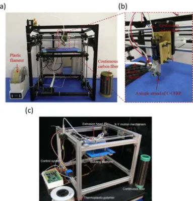
In 2014, R. Matsuzaki et al. were among the first to investigate the addition of continuous fibers in 3D printed composites to develop high performance materials. Their “in-nozzle impregnation”
technology has overcome the performance of short fibers composites and is today extensively studied. Next, industrial 3D printers capable of printing continuous fibers reinforced composites were commercialized, i.e. the MarkOne® and MarkTwo® from Markforged® (released in 2016) and the Composer® from Anisoprint® (released in 2019) (Figure 0.2).
Figure 0.2: Photography of MarkTwo® from Markforged® (left) and Composer® A3 from Anisoprint® (right).
An increasing number of companies are now working on the development of 3D printers capable of printing continuous synthetic fiber such as 9T Labs® and Desktop Metal® which are developing solutions for 3D printing of very high performance composites with very high fiber content (60 % vol.) and low porosity (< 1 %) for structural applications. Other company such as Arevo® and +Lab® are also working on 6 axis 3D printers, which combine AFP with 3D printing, to develop continuous fiber-reinforced structures of complex shapes. The stimulating potential of this technology and the performance of the associated composites has yet to be fully understood.
Beyond improving the mechanical performance of 3D printing composites, Skylar Tibbits from the Massachusetts Institute of Technology proposed the term of 4D printing in 2013. 4D printing is : “ (…) takes multi-material 3D printing to deposit multiple materials and add a capability of transformation to printed parts which are able to transform from one shape to another shape directly on their own (…)”. 3D printing capabilities are used in 4D printing to print multi-materials with precisely adjusted architecture to develop pre-programmed self-assembly structures. Hence, 4D printing makes it possible to obtain a self-assembled structure, self-repairing materials and adds multi-functionality to printed structures. Transformation properties of 4D printed parts are triggered by external stimulation, e.g. water, temperature, light or mechanical actuation. Many fascinating applications can be imagined with the help of 4D printing, especially for self-assembled structures. For example, one could imagine self-assembled buildings, many applications in the space industry could be targeted (deployment of solar panels or antennas without energy input, improvement of the transportation system for the International Space Station, etc…).
As a result of the current environmental situation described by the Special Report on Global Warming of 1.5°C published by the Intergovernmental Panel on Climate Change in 2018 that now well established (except for some climatosceptic), the way in which materials and structures are designed and manufactured is expected to change. Therefore, the selection of materials must be made with care and mechanical performance is not the only parameter to be promoted. Thus, local sourcing, renewability, low energy to be produced and finally end of life management are, among other things, the key parameters for conducting an eco-design approach. Manufacturing should induce low energy consumption and reduce waste.
In this way, natural fiber-reinforced composites and additive manufacturing are a relevant alternative to synthetic counterparts manufactured by conventional processes. Flax fibers like other bast fibers used to reinforce plant stems, have high stiffness and a strength-to-density ratio that is competitive with the properties of glass fibers. The Life Cycle Assessment (LCA) has also shown that flax fibers have a moderate environmental impact compared to glass. However, due to short-term research (around 20 years), compared to synthetic composites, biocomposites are still lagging behind in terms of technological maturity but also in terms of basic understanding. 3D/4D printing is an incredible opportunity for biocomposites to develop for the first time on the same time scale as their synthetic counterpart 3D printing of natural fibers composites.
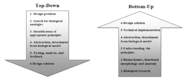
The development of 3D and 4D printing is progressing together with the optimization of design tools such as topological or parametric optimization. NASA has recently identified a synergistic effect to combine 3D printing and biomimicry through the possibility of manufacturing complex architectures. An increasing number of articles reflect this trend (Figure 0.3).
Figure 0.3: Number of publications for the period 2005-2020 in biomimicry and additive manufacturing (Adapted from Du Plessis et al, Additive Manufacturing, 2019).
The latter is now described by standards ISO_PRF_18458; ISO_PRF_18459 and could be done in two ways: Bottom-up (or Biology influencing design) with biological push approach and Top-Down (Design looking to biology or Problem-Driven Biologically Inspired Design) with an engineering driven approach.
Bottom-up is defined as: identifying a particular characteristic, behavior or function in an organism or ecosystem and translating that into human designs.
Top down approach is defined as: “Defining a human needs or designing problem and looking to the ways other organisms or ecosystems solve this”. Top-down approach of biomimicry has offered a new opportunity to overcome current material properties in terms of crack resistance, stiffness to weight ratio, damping and adaptability (morphing). In addition, this approach enables to turn the drawbacks of the materials into new functionalities. For example, natural fiber composites suffer from moisture which limits their use in outdoor semi-structural applications. Inspired by hygromorphic biological actuators such as the pine cone, Hygromorphic Biocomposites have been developed since 2015 by Le Duigou et al. as new multifunctional smart materials and combine the paradigm of biomimicry with eco-design. These materials are capable of changing shape autonomously in response to changes in humidity due to the anisotropic hygroscopic expansion of the natural fibers (fiber-dominated actuation) and their asymmetrical architecture. Autonomous morphing (or meteo-sensitive) included in a frugal design is a real advantage when aiming for low maintenance and extreme environment. However, market field of natural fibers based printable filaments is today limited to few products such Woodfill from Colorfabb (Polylactic acid filled with 30 % wt. of wood flour), Laywoo-D3 from Lay Filaments (Polylactic acid (PLA) filled with 40 % wt. of wood fibers) or Starflax® 3D from Nanovia® (PLA filled with flax fibers) for example. Moreover, non-open access 3D printers, only able to print their own materials (such MarkTwo® from Markforged® or Composer® from Anisoprint®), restrain further development.
To overcome current limitations, the objective of this thesis work is to provide more in-depth knowledge on the relationship between the 3D and 4D printing manufacturing process, the resulting microstructure, the mechanical and hygro-mechanical behaviors for two types of high performance composite materials.
Figure 0.4 present a schematic overview of this thesis work. The methodology is applied on continuous “off-the-shelf” synthetic fiber (Carbon, Glass) and on flax fiber composites produced on this occasion. Structural or semi-structural applications and morphing structures are targeted. First of all, the principle of 3D printing is exposed while a glossary and a global definition will be proposed.
Figure 0.4: Schematic overview of thesis work.
Then, in Chapter 1, a literature review on 3D printing of thermoplastic composites is performed with a focus on the 3D printing of continuous synthetic and natural fiber composites. This overview of current advances in 3D printing of composite materials is presented alongside work on conventional manufacturing and other additive manufacturing technologies such as Automated Fiber Placement (AFP) and Automated Tape Laying (ATL). On this purpose, the mechanical performance reached with 3D printed continuous fiber composites is discussed as well as current limitations and process improvements. Then, the 4D printing technology for polymer and composites materials is described and current research trends are presented for synthetic and natural fiber composites with regard to architecture and material optimization.
In Chapter 2, the different materials, experimental techniques and measurement protocols used in this study are presented and described. A first part is devoted to the selection of materials. A second section presents the 3D printing process. A third section presents the mechanical characterization methodology (tensile test, three-point bending and out-of-plane characterization). The fourth section displays the imaging techniques used to describe the composite microstructure. The fifth part shows the environmental conditioning used to evaluate the evolution of mechanical performance with respect to moisture or sorption. The sixth section describes the 4D printing procedure for continuous carbon fibers composites and continuous flax fibers composite with hygromorphic and electro-thermo-hygromorphic actuation and the last section presents the thermal characterization of the composites.
In Chapter 3, the mechanical characterization of two continuous fiber composites, carbon and glass fibers reinforced PolyAmide (PA) composites manufactured with a commercial 3D printer is shown. The relationship between the microstructure of the composite (voids, fibers orientation, printing strategy and edge effect) and mechanical performance is investigated by the means of three mechanical characterizations; tensile test in the fibers direction (longitudinal properties), tensile test perpendicular to fibers direction (transverse properties) and measurement of out-of-plane properties through Double Cantilever Beam (DCB) tests. Properties are discussed and compared to those of conventional manufacturing to establish a baseline for 3D printing with continuous fiber composites. As the polyamide matrix used is well-known for its chemical composition induced hygrosensitivity, moisture and water-induced properties are evaluated to identify i) their durability in wet environment and seawater conditions for marine applications and ii) their potential of matrix-dominated hygromorphism for smart 4D printed devices following biomimicry top-down rules. In Chapter 4, following the hygromechanical properties of printed continuous carbon fibers/polyamide composites, the design and development of a new paradigm of bio-inspired 3D/4D electro-thermo-hygromorphic actuators is presented. First, passive or autonomous hygromorphic behavior is characterized experimentally by following the evolution of responsiveness (curvature amplitude) and reactivity (curving kinetic) of asymmetric composites in various humid environments. Then, this study focuses on the control of moisture content and desorption kinetics within continuous carbon fibers/PA using a combination of electrical, thermal and hygroscopic stimuli. The applied current, thermal distribution, moisture content and the resulting actuation (amplitude and kinetic) are monitored. Finally, the influence of the printed pattern on the resulting actuation is studied and discussed.
Chapter 5 is based on the development of novel continuous flax yarns biocomposites based on Poly-lactic acid (PLA) using a customized 3D printer with tailorable properties. The multiscale investigation of 3D printed flax yarns reinforced biopolymer is carried out by studying the relationship between the slicer parameters (Layer height, interfilament distance…) on the microstructure and the resulting mechanical performance. Mechanical properties are discussed and compared to conventionally manufactured biocomposites (Injection molding or thermocompression).
Finally, chapter 6 presents 4D printing of continuous flax fiber (cFF) biocomposites with PLA and PBS matrices. The objective is to design and manufacture fiber-dominated Hygromorphic BioComposites. The design methodology is examined in terms of the use of 4D printing. Then, the selection of materials is presented in terms of matrix stiffness and strain with the characterization of the hygroelastic properties of cFF/PLA and cFF/PBS. Stiffness control with a local and progressive architecture of the cFF/PBS composite is investigated following the bending responsiveness and the reactivity given by the different interfilament Distance (ID). Finally, compliant (hinge-type) mechanisms are printed and tested. The last part of this manuscript is a general conclusion and perspectives to highlight the main achievements of this work and to discuss future studies and improvements.
Chapter 1: State of the art in 3D/4D printing of continuous
fiber-reinforced (bio)composites: achievements and future
This first chapter aims to present a state of the art on 3D printing of thermoplastic materials with Fused Filament Fabrication (FFF) with emphasis on synthetic and natural fiber reinforced composites for structural and morphing applications. Hence, after a general presentation of 3D printing technology with an exhaustive glossary, a description of FFF with thermoplastic materials is done to highlight the moderate mechanical performances. To overcome this drawback, two solutions are detailed, one focused on process parameters optimization and one on the material scale where the addition of reinforcing fibers is investigated. Two categories of reinforcing fibers are presented and discussed here, discontinuous and continuous fibers. The benefits brought by these fibers to 3D printed thermoplastic by FFF are displayed with an emphasis on the mechanical performances linked to the microstructure. This literature review provides a better understanding of the relationship between mechanical performance and microstructure and identifies the improvement required for 3D printed composites to reach structural applications.
However, in the composite industry there is a need to develop multi-functional composite materials. In this context, 4D printing (3D printing materials with time-dependent properties triggered by an external stimulus) has emerged in the late years. Section 4 describes 4D printing of polymeric and composite materials, summarizing the materials and stimulation investigated in the literature as well as the current limitations. This section also presents an overview of the future prospects for 4D printing of composite and polymeric materials.
Section 5 of this chapter details the literature research on 3D and 4D printing of natural fiber-reinforced composites. There is a growing interest in natural fibers in the composite industry. Indeed, they possess high specific strength (competitive to glass fibers properties) and a lower environmental footprint. Consequently, a growing number of research teams are now working on natural fiber-reinforced composites for 3D printing and these works are presented in this chapter. Moreover, natural fibers have shown great potential for designing multifunctional materials through the study of hygromorphic biocomposites (composites reinforced with natural fibers able to modify it shape in response to humidity) and, consequently, the addition of natural fibers in 4D printed structures is a promising new research trend.
1. General presentation of 3D printing and Fused Filament Fabrication
1.1. Principle of 3D Printing
3D printing principle is divided in five major steps. First, a numeric file is generated thanks to a numeric model developed by Computed Aid Design (CAD) that represents the desired part. CAD model can be generated thanks to two methods: design of the part with a CAD software or with a digitalization technique such 3D scanner. Numeric model is then generated in a file; most common used format is STL (Standard Tesselation Language) invented by the company 3D system which commercialized the first stereolithography (SLA) 3D printer [1]. Thus, STL file is uploaded in a software dedicated to 3D printing named slicer. This software slices the model layer-by-layer and defines the printing pathway for each layer and generates a G-code file. G-code is a language for computerized machine tools which summarizes all engine instructions (path to follow, how fast to move, which motors are required, etc…). Then, the 3D printing begins with the layer-by-layer built up of desired part. Depending on printing techniques and on part complexity, post-treatment may be required (polishing, chemical treatment to remove support; etc…). These 3D printing steps are summarized in Figure 1.
1.2. Glossary and definitions of 3D printing Fused Filament Fabrication process:
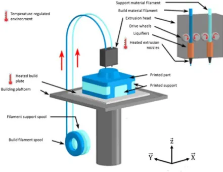
During printing, a polymer filament is brought to an extruder head by means of drive wheels. The extruder head is composed of driving wheels which pull the filament through a liquefier, a heating resistor which aims to heat the filament above it glass transition temperature (if it is an amorphous polymer) or above it melting temperature (if it is a semi-crystalline polymer). This liquefier heat-up an extruder nozzle where the molten polymer flows. The extruder head moves along X and Y directions (Figure 2) and deposits beads (extruded filament) following a raster (printing pattern defined prior printing). The bead is deposited in a heated build plate (or bed) placed on a building platform. When a layer is over, the building platform (or the extrusion head depending on 3D printer model) move vertically to let the extrusion head printing the followings layers until finishing the part [3].
Figure 2 : Schematic representation of FFF process showing the components of a 3D printer by FFF. Adapted from [4].
The following section aims to describe the main slicing and printing parameters used in 3D printing. The slicing parameters are related to the architecture of the material, while the printing parameters are related to the 3D printer itself. Figure 3 shows a schematic representation of these parameters.
Slicing parameters:
- Layer Height (LH) refers to the distance between the nozzle and the building platform of the printed layers.
- Raster/Air gap or Interfilament Distance (ID) refers to the distance between the center of two printed beads within a same layer.
- Raster Angle (RA) refers to the angle between nozzle trajectory during printing and the axis X. - Raster/Bead width is the width of deposited material. Small values lead to a lower production
time and material amount while high value allows to print stronger parts.
- Building orientation refers to the part orientation on the build platform with respect to X, Y, Z axes (Figure 3.b).
- Infill percentage is the percentage of matter within the printed structure.
- Infill pattern represents the trajectory of printed beads. In the literature, two patterns are used, i.e. concentric (Figure 3.c) and isotropic pattern (Figure 3.d).
Figure 3 : Schematic representation of FFF process parameters (a), building orientation (b), concentric (c) and isotropic (d) infill pattern [1], [5].
Printing parameters:
- Heated plate (or bed) temperature is the temperature of the plate where printed beads are deposed.
- Nozzle temperature is the temperature of extrusion nozzle and, therefore, material extrusion temperature.
- Deposition/Printing speed refers to the speed of printer head during printing process.
2. Overview of current research on 3D printing of thermoplastic materials with
Fused Filament Fabrication (FFF)
2.1. Presentation of FFF process for pure thermoplastics and current limitations Among the many 3D printing technologies, the most common method for printing polymers is Fused Deposition Modelling (FDM), also known as Fused Filament Fabrication (FFF), a trademarked material extrusion process patented by Stratasys in 1992 [6], [7]. In FFF, the thermoplastic filament is melted through a heated nozzle and the viscous polymer is deposited layer-by-layer onto a build plate where layers are fused together and, once solidified, create the final part [8]. This process is almost fully automatized, making this technology suitable for mass production. One of the main interest of FFF technology is its ability to precisely control the microstructure of the printed part and to locally control its properties (porosity, density and orientation) [9]. However, in order to shift FFF from the prototype stage to end products, a number of improvements are required [10]. These improvements are: a greater variety of available polymeric materials, a process improvement for better dimensional reliability, improvement in surface finish and finally, enhanced mechanical properties. As described in several articles, the mechanical performance of 3D printed parts is lower than their conventionally manufactured counterparts [11]–[13]. Masood et al. [12] observed that PolyCarbonate (PC) printed with FFF process exhibits tensile strength in the range of 70-90 % compared to injection molded PC parts . Similarly, Ahn et al. [11] studied Acrylonitrile Butadiene Styrene (ABS) and found that the tensile strength of FFF printed samples was 26 % lower than that of injection moulded samples.
Different strategies were investigated in the literature to improve the mechanical performance of FFF printed parts. The first one is the modification of the formulation of printable filaments through the addition of reinforcing fibers. This point will be discussed further in the section 3 of this chapter. The second strategy is to optimize printing and slicing parameters.
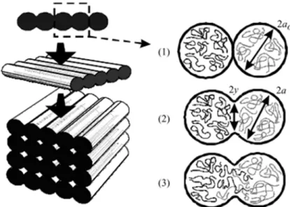
In 3D printed parts by FFF, the lower mechanical properties are mainly due to insufficient bonding strength between printed beads within and between printed layers, leading to poor interlayer strength as well as poor interbead cohesion and the creation of porosity. The adhesion between the printed layers is governed by the interdiffusion of polymer chains between the printed layers [14]. The formation of a bond between the printed layers and the adjacent beads in printed parts is similar to the process of welding polymer interfaces where similar physical mechanisms (i.e. reptation) are involved [15]. The formation of the bond interface is schematized in Figure 4 where the cross-section of the bead is idealized as circles.
Figure 4 : Schematic illustration of bond formation between adjacent beads. When beads are in contact (1), a neck between these beads is created (2). This neck formation occurs
because of the establishment of interfacial molecular contact by wetting. After establishment of connection between the beads, interdiffusion of polymer chains occurs
across the interface (3) and after extensive interdiffusion of polymer chains, a randomization is reached between the beads [10].
This mechanism of bond formation is driven by the thermal energy applied to the extruded material, the contact time and pressure between the printed beads. Bellehumeur et al. [16] described this phenomenon and evaluated it qualitatively through thermal modeling and sintering experiments. They showed that printing parameters such as extrusion temperature and filament size play a role in the growth of the neck of the bonding zone (Figure 4). However, complete bonding does not take place because the FFF process cannot maintain a high temperature long enough for complete bonding. Consequently, as mentioned previously, printed parts exhibit lower out-of-plane and transverse cohesion as well as lower mechanical performance than their conventionally
manufactured counterparts. Hence, key parameters for improving the mechanical properties of 3D printed thermoplastic parts are the enhancement of the interbeads and interlayer properties.
2.2. Parametric studies on 3D printed parts for the improvement of mechanical properties
In the literature, numerous studies have focused on the influence of printing parameters on the mechanical properties of 3D printed thermoplastic parts, especially with regard to tensile tests. Popescu et al. [17] divided the parameters of the FFF process into two categories :
Printing parameters – extruder temperature, bed/plate temperature and environment temperature, flow rate, deposition speed.
Slicing parameters – raster angle, layer height, raster width, interfilament distance, infill percentage, infill pattern.
All these parameters are linked to the quality of bead bonding described above, which determines the mechanical performance of the parts printed by FFF [18]. Figure 5 describes the main printing and material parameters that govern the quality of the parts as well as the sintering of the beads during 3D printing process. The viscosity and surface tension of the material dictate the flow characteristics in 3D printing, which is also driven by the temperature conditions.
Figure 5 : Main printing and material parameters influencing part quality and bead sintering [19].
For example, Zhao et al. stated that rheological behavior plays a significant role in the 3D printing process as low viscosities at high shear rates are required for easy low energy extrusion, but high
zero-shear viscosities are also required for the extruded to retain its shape once being out of the nozzle and deposited [20].
The heat capacity and conductivity of the 3D printed polymer affect the temperature profile of the printed beads [19], [21]. The categories of slicing and printing parameters are discussed extensively in the following sections.
.
2.2.1. Influence of printing parameters
During the printing process, different heat exchanges occur, by convection with the environment and by conduction between adjacent beads, the printer bed and the nozzle that leads to various and complex thermal state [22]. The temperature and cooling conditions therefore influence the level of crystallinity of the polymer, the bonding of the beads and thus the mechanical properties [8]. For example, Aliheidari et al. [23] studied ABS and showed through Double Cantilever Beam tests, that higher extrusion temperature leads to a higher delamination resistance and therefore a better interlayer adhesion. Consequently, increasing the nozzle temperature enhances the mechanical performance of the part, but too high a nozzle temperature can lead to material degradation and deformation of the structure, leading to dimensional inaccuracy [24]. During cooling, shrinking and residual stresses develop in the printed layer because of the temperature gradient within the part, which may cause delamination or warping [25]. Sun et al. [10] studied the temperature profile of a printed ABS bead as a function of the number of printed layers (15 and 30 layers). On this purpose, the authors placed a thermocouple on the heated plate to record the temperature profile of the first layer. Thanks to this method, they studied the influence of nozzle temperature and environment temperature on the temperature profile. The results are shown in Figure 6.
The authors showed that the temperature of the first layer rises periodically with each additional layer printed and then decreases rapidly as the nozzle move away from the thermocouple. The study of the influence of the process parameters (Figure 6.b, c) shows a minimum temperature (lower limit) increase, which means that the first layer undergoes the thermal influence of the other printed layers. Moreover, the nozzle temperature seems to have less of an influence on the temperature profile than the environment profile. Indeed, the authors did not measure a significant effect of increasing nozzle temperature, whereas a 20 °C increase in environment temperature (50 °C to 70 °C) leads to an increase in the minimal temperature (average of the lowest temperature reached at each deposition pass) from 73 °C to 87 °C.
Figure 6 : Influence of the number of layers on the temperature profile of first layer (Temperature nozzle = 270 °C and environment temperature = 70 °C) (a). Influence of environment temperature on the temperature profile of first layer (Nozzle temperature =
270 °C) (b). Influence of nozzle temperature on the temperature profile of the first layer (Environment temperature = 70 °C) (c) [10].
Several articles aimed at modeling the temperature profile in the printed bead to better understand the influence of bead bonding and cooling on internal stresses considering various assumptions and analytical models [26]–[28]. Costa et al. [29] studied the heat transfer during cooling of ABS beads. They have taken into account all physical contacts between the bead and the 3D construction in order to estimate the quality of the bond between printed beads and the evolution over time of the temperature of the beads. They demonstrated that the lower the extrusion temperature, the lower the adhesion between beads. They also showed an influence of ambient temperature with more areas of poor-adhesion at ambient temperature.
The printing speed also plays a major role on the mechanical performance of 3D printed parts, on the printing time and therefore, on the production cost. A higher speed rate allows the reduction of printing time but causes a drop in tensile properties [30], [31]. Ning et al. [31] attributed this drop to a lower contact time at the nozzle temperature between adjacent beads for higher velocity rate. Consequently, the printed beads are exposed for a shorter period of time to the heated nozzle and interdiffusion of the polymer chain is not promoted; leading to a lower quality of inter-bead and interlayer bond and affecting the mechanical performance.
2.2.2. Influence of slicing parameters
The influence of raster orientation is a slicing parameter widely studied in the FFF research [32]– [34]. The raster angle is defined as the angle between the X-axis of the 3D printer and the deposited bead (Figure 3.a). Literature studies indicate that a raster angle of 0° ensures better tensile strength. For example, Lanzotti et al. [21] studied PLA and observed a decrease in mechanical performance when the raster angle increases, with a 20 % difference between 0° and 90° in regard of the ultimate tensile strength. El-Said et al. [35] assigned this difference to the anisotropy of the printed parts. During the processing, polymer chains tend to align themselves along the raster axis [36] which explains the strongest properties in that direction. Moreover, as the raster angle becomes higher, the interbead interfaces are loaded, which negatively affects the tensile properties. In their study, analysis of fracture path for different raster angles (0°, 45° and 90°) revealed that the inter-bead bonding plays a major role in the tensile test (Figure 7).
Figure 7 : Schematic representation of the rupture geometry on 3D printed samples varying raster angle. For a raster angle of 0°, the break occurs within the printed beads and at the interface between the beads. For raster angles of 45° and 90°, the specimen breaks at the interface between the beads. For 45° and 90°, the bonding between adjacent
beads plays a more important role in the load transfer than for the 0° raster angle similarly as happens for fibers reinforced composites [35].
As mentioned above, the bonding between the beads is the weakest link in the printed part and leads to a decrease in mechanical properties as the raster angle increases.
In the literature, slicing parameters are considered to be the most influential process parameters on printing quality as they are directly related to the microstructure of the material. The most significant influencing slicing parameters are: layer height, infill percentage and air gap or interfilament distance [17]. These parameters are critical for the quality of the bonding strength, the porosity content and, consequently, for the mechanical performance of the 3D printed parts.
-Layer Height is widely studied in the literature and research teams observed that optimal tensile strength of polymer is reached with minimal layer height [37]–[39]. Sood et al. [40] studied ABS and attributed the highest tensile strength for the thinnest layers to a normal pressure driven molecular diffusion between the adjacent beads and layers (interdiffusion mechanism). Hence, during the 3D printing process, considering higher number of layers for a constant sample, the part undergoes more heating and cooling cycles that promote molecular diffusion between printed layers.
Zhang et al. [41] created a model to simulate the FFF deposition process and predicted residual stresses and distortions of ABS parts as a function of the process parameters (layer height, raster width and printing speed) and selected the layer height as the most influential parameter. The authors simulated the evolution of maximum first principal stress as a function of layer thickness, raster width and printing speed and observed a higher stress accumulation for a greater layer thickness, leading to distortion of the part, a degradation of the inter-bead bond strength and reduction of the mechanical properties.
- Infill and related interfilament distance are linked parameters. They have a direct influence on mechanical strength, dictating the contact area between adjacent beads in the X and Y directions (Figure 2) and therefore the bond strength. A lower infill percentage speeds up the 3D printing process, reduces the use of materials and therefore costs [13]. The infill percentage is controlled by the interfilament distance parameter which represents the distance between the printed beads (Figure 2). The higher the interfilament distance, the lower the infill density and, consequently, the porosity content increases and the number of connections between adjacent beads also decreases, resulting in lower mechanical performance [42]. In the literature, optimal mechanical performance is observed with a slightly negative interfilament distance (infill over 100 %) which physically means that the printed beads overlap, implying low porosity content [43]. Figure 8 shows the evolution of
cross-section surface of a 3D printed ABS part over infill density evolution, showing a qualitative decrease of porosity content when infill percentage increases.
Figure 8 : Scanning Electron Microscopy images of cross-section of 3D printed ABS parts with several infill percentage [43].
Finally, the mechanical performance depends on the slicing and printing parameters which is often felt as negative points. However, the mechanical properties are adjustable through the control of the process parameters giving more degree of freedom to the designer.
It must be kept in mind that the mechanical performance of 3D printed parts remains lower than their conventionally manufactured counterparts. In order to overcome this major issue, several research works have focused on the 3D printing of composite materials through the addition of reinforcing fibers in the printable filament.
3. 3D printing of fiber reinforced composite materials
The addition of reinforcing fibers in printable filaments follows two strategies. The first one is the addition of discontinuous fibers to improve mechanical performance, reduce warping during printing and increase dimensional stability [14]. The second is the addition of continuous fibers used to greatly improve mechanical performance. In the following section, both strategies and the respective studies are presented and discussed.
3.1. 3D printing of discontinuous fiber-reinforced composites
To the best of our knowledge, the first literature research which aimed at reinforcing FFF printed parts with discontinuous fibers was conducted by Zhong et al. in 2001 [44]. In this research, the authors aimed to develop a printable filament made of ABS reinforced with short glass fibers using a twin-screw extruder. The authors observed an improvement of mechanical performance with the addition of glass fibers (+140 % between pure ABS feedstock and ABS reinforced with 11.4 % vol. of short-glass fibers) but also a strain reduction. Strain was improved thanks to addition of plasticizer and compatibilizer. Following this research, several teams have worked on the addition of fibrous reinforcement such as carbon nanotubes [45], [46], graphene [47], [48] or carbon/glass short fibers [31], [49], [50].
Actually, 3D printing of discontinuous fiber-reinforced polymer composites shows several advantages compared to neat thermoplastic 3D printed parts.
First, mechanical performances are improved by the addition of short fibers. Ning et al. [49] showed that the addition of 4.5 % vol. of short carbon fibers improved the tensile strength (+24 %) and the modulus (+27 %) compared to neat ABS. Love et al. [51] showed that the addition of 8 % vol. of short carbon fibers to ABS leads to an increase in tensile modulus (+630 %) and tensile strength (+144 %). Jiang et al. [52] investigated the addition of carbon fibers to three different matrices (ABS, polylactic acid (PLA) and polyethylene glycol (PETG)). The authors investigated three fibers fraction, i.e. 10.5 % vol.; 9.4 % vol. and 14.3 % vol. for ABS, PLA and PETG; respectively. The authors measured a strong increase in tensile strength (+211 % for ABS-based composites, +164 % for PLA and +314 % for PETG) and tensile strength (+33 % for ABS-based composites, +14 % for PLA and +48 % for PLA). Carneiro et al. [53] showed that addition of glass fibers to polypropylene (PP) leads to an increase of 30 % and 40 % for the modulus and the ultimate tensile strength, respectively. These results are displayed in Figure 9.
Second, the introduction of fibers leads to a lower coefficient of thermal expansion which reduces the thermal strain gradient during 3D printing and therefore limits warping during the process [51], [54]. Finally, short fibers made it possible to achieve greater geometric precision and subsequently improve the surface appearance of the printed structures [51]. Greater dimensional stability allows to develop new fields of application such the Big Area Additive Manufacturing (BAAM) [55], [56] where large scale structures are printed like a boat at the university of Maine [57].
Figure 9 : Tensile modulus (a) and ultimate tensile strength (b) of samples 3D printed with pure polypropylene (PP) and polypropylene reinforced with 17.6 % vol. of glass fibers
(GRPP) [53].
As with thermoplastics, the 3D printing of short-fiber reinforced composites is strongly dependent on the process parameters [31]. As discussed in the previous section, the most influential parameters are raster angle, layer height, interfilament distance. In 3D printing of short fiber composites, fiber type, content, orientation, aspect ratio (L/d), and fiber/matrix interactions also play a major role on mechanical performance.
Tekinalp et al. [50] used Bay and Tucker’s method [58] to characterize the fiber orientation in the FFF process and compared it to compressed molded samples. The authors demonstrated that 90 % of discontinuous fibers in FFF are oriented along the printed path while samples elaborated by compression molding exhibit a more homogeneous fiber distribution. Mulholland et al. [59] studied the evolution of fibers orientation in relation to filament extrusion and FFF printing for PA6 matrix reinforced with 20 % vol. of short copper fibers (500 µm long and 30 µm width). They observed that after the extrusion process, the fibers are preferentially oriented in the direction of extrusion and that this orientation is maintained during the printing process with a slight decrease of fibers orientation from 80 % to 68 %. Garcia et al. [60] modeled the evolution of fibers orientation within the nozzle with Moldflow®. Material modeled is a Thermocomp RC004SXS made by SABIC Innovative Plastics US, LLC filled with 20 % vol. of discontinuous carbon fibers. A representative example of model representation in displayed in Figure 10. In this Figure, red color corresponds to a fibers orientation in the Z direction near 1 while blue areas represent a fibers orientation near 0. This model shows that fibers tend to align in the section reduction of nozzle head due to higher shear stress [54] and decrease of die swell acting perpendicular to shear flow.
As described in the literature, tensile properties are maximized when the samples are oriented in the direction of stress [61]–[63]. Thus, filament extrusion allows the short fibers to be oriented in the
direction of the filament. The fiber orientation is maintained during the 3D printing process, and then control of the fiber orientation in the printed structure is possible by controlling the raster angle.
Figure 10 : Representation of short carbon fibers orientation tensor in Z direction within a printer nozzle [60].
Another parameter that dictates the mechanical performance is the influence of fiber length. Ning et al. [49] studied the influence of carbon fiber length on the tensile properties of ABS-based composites and observed higher tensile modulus and tensile strength for longer fiber length (150 µm instead of 100 µm) but observe no change in yield strength. The decrease in tensile modulus and tensile strength with a shorter fiber length is well-known for conventionally manufactured short-fiber composites and is explained by lower fiber efficiency [64], [65]. Moreover, a minimal fiber length,
namely the critical Lc fiber length, is defined in the Kelly model and shown in Equation 1 where rf is
fiber radius, σ the composite tensile strength and τi the interfacial shear strength between matrix
and fiber. When the length of the fibers is greater than Lc, the fibers act as a reinforcement with
sufficient load transfer to the fibers, but when the of the fibers is less than Lc, the load transfer is not
sufficient and matrix/fiber debonding occurs at the interface during the tensile test.
𝐿 = Equation 1
However, in 3D printing, the length of the fibers is limited by the extrusion process used to manufacture the printable filament, which causes long fibers to break. Moreover, the length of the fibers is limited by the viscosity of the filament: A longer fibers length leads to a higher filament viscosity, which makes the 3D printing process more difficult due to the clogged nozzles.
The volume content of fibers in the printable filament affects the mechanical performance of 3D printed structures; the higher the fiber content, the higher the mechanical properties. However, this increase becomes less significant for fibers content above 20 % wt. (15 % vol.) as displayed in Figure 11.
Figure 11 : Effect of fiber content and preparation process on (a) tensile strength and (b) tensile modulus of ABS/CF composites [50].
Ning et al. [49] observed the same results, but also noted the appearance of porosity with increasing fiber content, as shown in Figure 12.
Figure 12 : Scanning Electron Microscopy observation of fracture surface of ABS/CF samples after tensile testing showing an increasing of porosity content for higher fiber
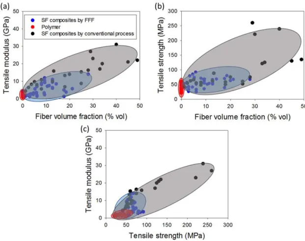
Consequently, there seems to be an upper-limit of fiber content for short fiber-reinforced composites, where the mechanical properties drop due to the appearance of un-impregnated areas, which affects the void content and induces a decrease in mechanical properties. Moreover, it is now well-stated that it is not possible to print filaments with a volume fiber content higher than 30 % vol. because of processability issues such as a nozzle clogging due to the excessive viscosity of the filaments and nozzle shear stress too low to extrude processed filament [5]. Figure 13 summarizes the tensile properties found in the literature for short fibers composites elaborated by FFF compared to pure thermoplastic printed parts and short fiber composites elaborated by conventional processes.
Figure 13 : Literature review on the tensile properties of short fiber based composites manufactured with 3D printing. Evolution of tensile modulus (a) and tensile strength (b) as
a function of volume fiber content; tensile modulus as a function of tensile strength (c) [46], [49]–[53], [56], [61], [63], [64], [66]–[76].
In conclusion, the addition of short fibers in printable filaments improves the mechanical performance of 3D printed structures compared to pure polymer 3D printed structures and
![Figure 8 : Scanning Electron Microscopy images of cross-section of 3D printed ABS parts with several infill percentage [43]](https://thumb-eu.123doks.com/thumbv2/123doknet/14556399.726085/38.918.140.780.184.443/figure-scanning-electron-microscopy-images-section-printed-percentage.webp)
![Figure 26 : Microscopic view of cross-section of 3D printed CF/PA6 composites without (a) and with (b) compression molding [107]](https://thumb-eu.123doks.com/thumbv2/123doknet/14556399.726085/60.918.166.746.92.348/figure-microscopic-cross-section-printed-composites-compression-molding.webp)
![Figure 27 : Schematic illustration of micro-screw in-situ extrusion based 3D printed continuous carbon fibers PA12 composites [132]](https://thumb-eu.123doks.com/thumbv2/123doknet/14556399.726085/61.918.190.733.719.1027/figure-schematic-illustration-extrusion-printed-continuous-carbon-composites.webp)
![Figure 29 : Fibers pathing around a 6 mm hole feature and fibers path in straight woven section (red lines indicate fibers path and placement [148]](https://thumb-eu.123doks.com/thumbv2/123doknet/14556399.726085/65.918.167.713.90.320/figure-fibers-pathing-feature-straight-section-indicate-placement.webp)