First International Conference on Bio-based Building Materials June 22nd - 24th 2015
Clermont-Ferrand, France
MECHANICAL CHARACTERIZATION OF NATURAL FIBRE-REINFORCED
EARTH PLASTERS
F.Rojat1*, M.Olivier1, A.Mesbah2, BF. Xiao² 1 CEREMA-DT-CE, CS92803, Bron, France 2 ENTPE, LGCB, 69518 Vaulx-en-Velin cedex, France
*Corresponding author; fabrice.rojat@cerema.fr
Abstract
The Bioterra ANR project aims to identify, characterize and offer solutions with low environmental impact, to microbial proliferation on earth bio-based products (bricks and plasters). As part of this project, this paper deals with the mechanical characterization of earth plasters: the objective is to identify products meeting the main conditions of use for construction, as a basis for further research on microbial development. Several testing methods are presented and are applied on 2 different plaster formulations composed of clay, sand, water and various natural fibers. The following properties are studied : shrinkage, compressive strength, flexural and Brazilian tensile strength, abrasion. The testing procedure includes the preparation of large plaster slabs to ensure a representative fiber distribution within the test specimens. The plates are dried under stable humidity conditions and the drying process is monitored by successive weightings. Then the specimens are cut inside the plate for mechanical testing. The paper shows a full description of the testing procedure and presents the resistances obtained for various plaster formulations. It yields interesting results about the expected properties of natural fiber-reinforced earth plasters and proposes some criteria for product acceptability.
Keywords:
earth plaster, fiber, testing protocol, compressive stress, tensile stress, abrasion test
1 INTRODUCTION
For the last 40 years or so, a large growing interest has been given to earth construction, mainly due to its physical, mechanical, thermal, environmental and economic properties. Many technics exist nowadays, some are quite ancient (adobe, rammed earth), and some very modern (compressed earth blocks). Earth plasters have been used for thousands of years. They may be realized with many different raw materials, often mixed with fibers such as straw, coco, sisal… They are nowadays particularly appreciated because of their aesthetic aspect, their good capacity for site implementation, and their probable contribution to the hygro-thermal comfort of living places.
However, there is now a need to evaluate the effective mechanical properties of earth plasters, namely because they are very often manufactured on-site, by the contractor himself.
In addition, the plasters involving fibers usually do not include hydraulic binders, their drying and strengthening is only due to clay, and the fibers entail anisotropy due to their implementation on the walls. As a consequence, the conventional testing procedures used for “classical” cement mortars and plasters are not very well adapted to earth-fiber plasters.
The Bioterra ANR project aims to identify, characterize and offer technical low environmental impact solutions to microbial proliferation on earth bio-based products (bricks and plasters). Seven different plaster formulations are studied during the research program in order to identify products meeting the main conditions of use for construction, as a basis for further research on microbial development. Several testing methods have been developed to characterize the following mechanical properties of earth-fiber plasters: compressive strength, tensile and flexural strength, abrasion tests, adhesion, and density. In this paper, only compressive, tensile and abrasion testing protocols and tests results are presented for two materials.
2 THE NEED FOR SPECIFIC TESTS
Earthen plasters have long been considered as having a sole aesthetic and protection role, which does not need high or well-known mechanical characteristics. This explains the small amount of studies and norms on the subject. However, in some cases, for instance in load-bearing straw bale construction, earth support plaster is a part of a structural complex that associates straw bales and a layer of earth fiber plaster on each side, each of the materials being perfectly linked to each other. For the calculation of such a structural
complex, mechanical data are needed [Olivier &al. 2012]. . In the same way, ready-to-use eartlh-fiber plasters may necessitate reproducible testing protocols in order to characterize the production homogeneity. The recent French professional rules related to the implementation of earth plasters for earth walls, produced by [Réseau Ecobatir & al 2012] present on-site best practices, but give few extensions about mechanical properties. In Germany, a recent norm [DIN_18947 2013] proposes a complete testing protocol to characterize ready-to-use earth plasters. It is mainly based on the protocols used for conventional hydraulic plasters [EN_1015-1 to 15]. Some difficulties appeared in the use of this protocol, as shown for instance in [Delinière & al. 2014] for the measurement of adherence. Some more questions are tackled later on in this paper.
Some other authors have published information about earth plaster behavior, related to various subjects, [Maddison et al. 2009] (humidity buffer capacity), [Ashour et al. 2010] (influence of fibers on the ductility of the material), [Darling et al. 2012] (impact of plasters on indoor air quality), [Hamard et al. 2013] (shrinkage and shear tests to assess the suitability of plasters) are examples of recent research on these materials. However, most of them do not insist on how to obtain in a laboratory, testing specimens that reasonably represent on-site conditions. They do not either question the modalities for testing their mechanical characteristics.
As a consequence, the aim of this research performed at CEREMA and ENTPE is to establish:
• a protocol to manufacture earth-fiber plasters samples that reproduces as well as possible the product realized on site
• and mechanical characteristics testing procedures adapted to the behavior of earth-fiber materials, that means, leading to reliable test results.
3 SAMPLE PREPARATION
The very first issue in this project was to manufacture samples representative of the ones realized on site. 3.1 Questions about sample size and format In the case of conventional plaster that contains hydraulic binders, samples are currently 11*22cm cylinders. For these materials, hardening is mainly due to hydraulic chemical reactions, for which water moisture must be homogeneous and kept long-lasting. Cylinders answer perfectly the question because they are waterproof and lead to large-size samples, easy to realize and representative of these material.
In the case of earth-fiber plasters, there is no hydraulic hardening. These plasters only dry, which leads to a drop of the manufacturing water content down to 1 or 2%. If implemented in a 11*22 cm cylinder, the drying would be extremely non-uniform because drying would occur only through the superior horizontal surface of the cylinder. The water moisture flux entails the creation of internal tensile stresses and cracks due to shrinkage. This drying and hardening process is not representative of the real on-site material. In fact, the plaster thin thickness (3-4 cm), as well as the implementation methods, leads to a quite rapid drying and to a homogeneous shrinkage crack distribution. In addition, such plaster spread on a wall leads to a preferential orientation of the fibers, namely along a
plan parallel to the wall. This is why it is difficult to obtain representative samples using 4*4*16 cm molds, as it was proposed in the German norm for earth plasters without fibers. In fact, with this kind of mold, current 3-5cm fibers are much too long and their distribution is no longer representative of the on-site conditions.
3.2 Proposed sample size and format for earth-fiber plasters
The first step of the proposed solution consists in realizing plaster slabs, 50*50 cm, thickness 3-4cm, depending on the material. A soft plastic film has been set at the bottom of the mold to avoid sticking, allow plaster shrinkage and prevent cracks. Plaster is implemented at its workability optimum water content, as on site. It is then kept for drying at 20°C and 60% humidity, so as to be representative of on-site plaster drying.
Pict. 1: plaster slab, 50*50 cm
The second step is the drying period. Slabs are regularly weighed. Curves are plotted during this step. These curves (see Fig. 3) also give indications on the curing duration, depending on temperature and local hygrometry.
The third step consists in the manufacture of small samples to be later used for the determination of different mechanical characteristics. The steps are the following:
Remove the slab, once it is sufficiently dried. A moisture content monitoring is done during the curing period.
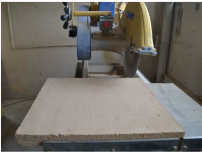
Suppress the 2-3 cm edge of the slab to eliminate the edge effects (due to folded fibers and shrinkage). Cut the slab into 4 cm wide pieces, with the help of a
thin diamond saw (same as used for rock samples) that produces little vibrations. The sawing needs to be very slow to obtain good quality parralelepipoids. Exam of these samples shows that the fibers stay undamaged, and perfectly connected to the clayey matrix.
Pict. 2: sawing of a plaster slab
The 4cm wide strip is then cut into pieces 4*4*16 for flexural tests
4*4*8 for compressive and tensile tests 4*4*4 to test anisotropy effects (see later)
Pict.3: samples obtained from a 50*50 cm slab
4 PHYSICAL AND MECHANICAL
CHARACTERISTICS 4.1 Shrinkage measurement
It is possible to quantify the global shrinkage of the slab given by the size of the surrounding crack. The measure is done with a precise rule, along the two horizontal dimensions, and with 3 measures per direction.
Shrinkage is calculated as follows: 0
/ l
l
R=
∆
ε
(1)With: ∆l: length variation, and l0: initial length
Pict. 4: shrinkage of a plaster slab
Of course, this value is only indicative, but it allows comparisons between several formulations. On-site values may show sensible differences, depending on the wall and on the implementation itself.
Also, during the drying step, visible cracks may appear in the middle of the slab. The positioning of a plastic soft film under the slab greatly improves this behavior. 4.2 Evaluation of final dry density
Plaster dry densities are calculated on several samples, from direct size measures, before test implementation.
4.3 Tensile tests
Flexural Tensile test
They are realized on 4*4*16 cm samples, with a 3-point test bench, like those used for conventional mortars.
Speed displacement of the press piston is 0.00208 mm/s up to rupture. Flexural tensile stress is:
F
bd
Fl
R
tf0
.
00234
2
3
2≈
=
(2)with F: loading strength upon rupture b: sample width (4cm)
d: sample height/thickness (4cm) l: distance between fulcrum (100mm)
A Young’s modulus can be calculated from the stress/strain curve at 50% of the failure stress.
Brazilian tensile test
Brazilian tensile tests are realized with 4*4*8 cm samples. It consists in breaking the samples between two thin strips so as to apply a pressure on the two opposite faces (see fig1). The force is applied through a displacement of the press piston at 0.00208 mm/s.
Fig. 1: Brazilian tensile test principle
Brazilian tensile stress is:
bL
F
R
tBπ
2
=
(3)with F: loading strength upon rupture b: sample width (4cm)
d: sample height/thickness (4cm) l: distance between fulcrum (100mm) 4.4 Compressive tests
Handling anisotropy
The anisotropy due to the fiber distribution needs to be taken into account in the compressive tests. They will
be performed in both direction to quantify this anisotropy. Rendered wall thickness Direction // to the wall Direction ⊥ to the wall Slab
Fig. 2: Parallel and perpendicular direction
(Tensile tests are only realized along a parallel direction to the wall.)
Compressive test in the // direction
These tests are realized on the 4*4*8cm samples, placed in the vertical position. The piston speed is 0.0208mm/s up to failure.
Different testing protocols have been set to take into account the lack of surfaces parallelism or the defaults of surface quality [Rojat 2014]:
All samples are tested with ball joints between the sample and the press piston
Several devices have been tested to improve the contact between the press and the sample: surface treatment, anti-friction system made of Teflon in particular. They did not notably improve the test results when the specimens had an aspect ratio of two.
The compressive stress is calculated upon failure. Young’s modulus is calculated at 50% of the failure stress, along a linear curve. However, this value is not perfectly representative because it does not take into account the friction between the press and the sample. But on the other hand, it is not possible to place strain gauges on such materials.
Compressive test in the ┴ direction
In order to quantify the compressive stress within the thickness of the plaster, 4*4*8 cm samples have been reconstituted from two 4*4*4 samples, hold together with Paris gypsum.
The testing protocol is the same as before. 4.5 Abrasion tests
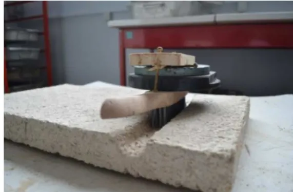
This test aims at qualifying the capacity of an earth-fiber plaster to resist to erosion due to friction. It has been designed from a test included into the XP-P 13 901 French norm for earth block acceptability. It consists in brushing the slab with a metal-brush. The brush is loaded with a 3kg load, and a forth and return movement is applied during one minute at a rate of 1 movement per second.
The result of the test consists in quantifying the weight loss of the slab:
1 0
)
/
²
(
m
m
S
g
cm
Ca
−
=
(4)with S: abrasion area (in mm²) m0: initial sample weight
m1: final sample weight
The higher Ca is, the more abrasion resistant the material is.
Pict. 5: abrasion test on a plaster slab
5 TESTS RESULTS
5.1 Composition of the 2 plasters
Two very different earth-fiber mixtures have been used for the tests:
The F5-plaster is a commercial-type material. F5 plaster is a 0/4 mm fine-grained material made out of clay-limestone fines produced from the sludge generated in washing units of a quarry. It is a A2-class material mixed with a 0-4 mm quarry sand. It contains short flax fibers (1cm), a low quantity of clay and a high percentage of grains. It also includes a stabilizer and an anti-dusting agent of unknown natures. It is a ready-to-use material. 18% water are added to obtain a handling similar as on site.
The F1 -plaster is a home-made mixture, optimized by the authors with the help of craftsmen. It contains clay, 0/4mm sand, and straw fibers (3-5 cm). Its composition is: clay (8kg, -19%), 0/4mm sand (24kg, -56%), fibers (0.38kg, 1%), water (9l, 28,3% including sand humidity). The mix is realized with a worksite mixer.
5.2 Geotechnical characteristics
Only F1 materials geotechnical characteristics have been determined by the CEREMA COFRAC laboratory of Bron.
Tab. 1: geotechnical identification of F0 plaster and initial material
Material seive 2µm 10µm seive 40µm seive 80µm seive 0.5mm seive seive 2mm 10mm sieve wl IP VBS
Kaolinite clay (F1) 44 71 85 94 96 99 100 61 28 3.5 0/4 sand 1 3 6 8 23 54 100 - - 0.05 Clay-limestone fines (F5) 14 48 85 97 99 100 100 - 18 1.8
5.3 Drying process
The following graph shows the drying curve of F5-plaster used in the Bioterra project. It is interesting to notice that several other formulations have been tested and show a nearly similar drying speed, whatever the initial water content value. Moreover, it can be observed that the delay for total drying is quite long in this experiment (up to 1 month). This can be related to a lack of ventilation in the drying room, leading to lower daily evaporation compared to what is usually observed on site (10-15 days).
41746 41760 41774 41788 41802 0% 5% 10% 15% 20% 25% 30% F1 F5
Fig. 3: drying curve of F1 and F5 plaster slabs
Another set of samples was kept in a different hygrometric condition. Drying was much faster, and here again, all materials let appear the same drying speed.
In both conditions, the drying is linear until residual water content is lower than 4%. The final water content depends on the materials. It varies between 0.5% (for washing fines) and 2% (for kaolinite clay). The samples are sawn out of the slab once the water content is stabilized.
Dry density of both plaster have been measured on 4 samples minimum :
F0 : 15,72 kN/m3 +/-0.01 ; F5 : 17.10 kN/m3 +/-0.03 5.4 Flexural and Brazilian tensile tests
Both tests have been performed, on 6 samples. Results are the following :
Tab. 2: F0 &F5 Flexural and Brazilian tensile tests results
material Flexural tensile strength
Brazilian tensile strength
F1 +/- 0.06 MPa 0.35 MPa 0.11 MPa +/- 0.02 MPa F5 +/- 0.05 MPa 0.91 MPa 0.20 MPa
+/- 0.05 MPa
Pict. 6: F1 Flexural and Brazilian tensile tests
Pict. 7: F5 Flexural and Brazilian tensile tests
The industrial F5 plaster obtains the higher strength, but an abrupt failure. Result dispersion is the highest. The F1 presents a more ductile failure, due to the fibers.
Fig. 4: flexural tensile strength-displacement curve, with F1 plaster
This flexural test appears to be really reproducible, much better than the Brazilian Test. This is due to the presence of fibers. Moreover, the values given with the Brazilian test are much lower than those obtained with the flexural test. Explanations may be : • During the Brazilian test, the failure process is
generated by a point-load process that leads to fracture coalescence inside the specimen. In this behavior, the fibers are not really solicited. • In the Brazilian test, load is transferred through a
rod that is rather wide compared to the sample. It then entails a large compression area under the rod, and the test becomes drastically not homogeneous.
However, Brazilian test gives good and reproducible results when there are no fibers.
Fig. 5: flexural tensile strength-displacement curve, with F5 plaster
5.5 Compressive strength
Compression tests have been performed on 4*4*8 samples, either cut directly in the slab or reconstituted from two 4*4*4 samples stuck together with gypsum. The reconstituted samples allow obtaining strength values in the direction perpendicular to the wall in order to evaluate anisotropy while keeping a 2:1 slenderness. Six samples have been tested in each case to reduce uncertainties. Results are the following:
Tab. 3: F1 & F5 compressive tests results, both directions material compressive strength parallel to the wall compressive strength perpendicular to the wall
F1 +/- 0.02 MPa 0.26 MPa +/- 0.07 MPa 0.53 MPa F5 +/- 0.15 MPa 1.06 MPa +/- 0.21 MPa 1.22 MPa For both plasters, the failure stress along the perpendicular to the wall is clearly higher than the other direction. This result is interesting in the case of loadbearing straw bale construction, where support plaster has a structural role. It also shows that anisotropy appears in the plaster, related to preferential fiber orientations during the laying out. This anisotropy is more important with long fibers (F1 plaster).
Pict 8: compressive test, F1 perpendicular and F5 parallel direction
As for the test itself, the results obtained on such different materials shows a light dispersion, between 10 and 15%, whatever the test direction. Reconstitution of 4*4*8 cm samples from 2 samples 4*4*4 stuck together with gypsum appears to be a good solution to avoid friction problems. Gypsum has a low influence on the compressive stress, which can be seen from the vertical failure crack going through the gypsum layer.
0 50 100 150 200 250 300 350 400 450 500 0 1 2 3 4 5 S tr e n g th ( N ) Displacement (mm)
F1 - Uniaxial compressive strength parallel to the wall on 4x4x8 samples
Fig. 6: compressive strength-displacement curve, with F1 plaster
The samples slenderness is equal to 2. As visible on the above pictures, friction between the samples and the press has a limited effect on the lateral deformation of the samples. The compressive stress is not over-evaluated by a triaxial effect.
Would the tests have been conducted on 4*4*4 cm samples, the results would have been much higher, and would not reflect the real compressive resistance of the support plasters.
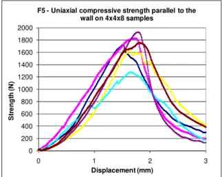
0 200 400 600 800 1000 1200 1400 1600 1800 2000 0 1 2 3 S tr e n g th ( N ) Displacement (mm)
F5 - Uniaxial compressive strength parallel to the wall on 4x4x8 samples
Fig. 7: compressive strength-displacement curve, with F5 plaster
5.6 Shrinkage tests
The mean shrinkage has been evaluated on the slabs.
Tab. 4: F1 & F5 shrinkage tests results material Shrinkage (%) Manufacturing water content F1 +/- 0.12 3.30 28.3% F5 +/- 0.31 1.83 17.5%
Shrinkage is directly related to the initial water content and the type of clay. The more water is needed for handling, the larger shrinkage is.
However, as long as the water content is optimize by the masons, shrinkage is maintained to a satisfactory level. In the F1 case, 3% shrinkage represents 10 0.3mm thin cracks per meter.
5.7 Abrasion tests
This test has been performed only on a few number of samples.
Tab. 5: F1 & F5 abrasion tests results
material Abrasion test : Ca (cm²/g) F1 0.05 0.05 . F5 0.37 0.29 0.34
Even if this test seems rustic, it appears than it is rather reproducible. It has, in fact, been tested with other plasters leading to Ca values varying from 0.05 to 0.36 cm²/g. Further tests will be performed so to see if it could become a distinguishing performance criteria.
Pict. 9: abrasion test reproducibility
The XP-P 13 901 norm for compressed earth blocks consider that Ca Value for earth blocks to be implemented in an outer wall should be equal to 2. From our experience on different plasters, a minimum 0.25 Ca-value seems necessary in order not to entail a prejudicial dusting. Such plasters (Ca>0.25g/cm²) produce few dust under hand-rubbing.
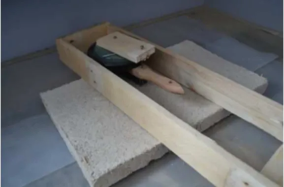
During the abrasion test and along with the XP-P 13 901 norm, the groove should not exceed by more than 2mm the 25mm wide metal brush. Indeed, this final width was impossible to reach with any of the tested plasters, even with the help of the wooden guide (see pict 10).
Pict. 10: wooden guide for abrasion test
Later on, in the framework of a earth-fiber plaster norm, the minimum Ca value should more deeply questioned.
6 CONCLUSIONS
The aim of this study was to establish testing protocols for reproducible and relevant tests to evaluate the mechanical performances of support earth-fiber plasters. The objective was to be able to sort plaster performances, but also obtain mechanical characteristic values to be alter introduced in a structure model.
The results presented in this paper show that : The manufacturing process, based on 50*50cm
slabs, lead to representative samples, closer to on-site implemented plasters.
Apart from the Brazilian tensile test, the other protocols proposed for earth-fiber plaster appears to be reproducible. Standard deviation is around 10% for most of the tests.
Sample slenderness equal to 2 obviates the use of anti-friction devices. When slenderness is lower than 2, the anti-friction devices become compulsory if a real compressive uniaxial stress is required.
Elasticity modulus could not be obtained directly off the sample, but only from a global value established with the press piston displacement. The real value is probably higher (stiffer modulus), but it gives a possible comparison reference between several materials.
The compressive tests confirmed that the laying out of the plaster entails anisotropic effects, more effective with long fibers.
Further experiments are going on in order to propose a full set of protocols for the different tests, and experiment them with a larger range of earth-fiber plasters. These experiments will also compare the influence of different parameters on the mechanical behavior of earth-fiber plasters.
7 ACKNOWLEDGMENTS
The authors are very grateful to the French ministry for ecology, sustainable development, and energy (MEDDE), for their support during this study. The sole responsibility for the content of this publication lies with the authors. It does not necessarily reflect the opinion of the Ministry.
The "Bioterra" project is supported by ANR and French ministry for ecology, sustainable development, and energy (MEDDE).
The author wishes to address their special thanks to. Bing Feng Xiao, ENTPE intern, and to Didier Millon and Bernard Carnus, CEREMA laboratory technicians.
8 REFERENCES Paper in a journal:
[Ashour 2010], Ashour T., Bahnasawey A., Wu W., Compressive strength of fibre reinforced earth plasters for straw bale buildings, Australian Journal of Agricultural Engineering 1(3), 2012, 86-92. [Darling 2012], Darling E. K., Cros C. J., Wargocki P., Kolarik J., Morrison G. C. & Corsi R. L., Impacts of a clay plaster on indoor air quality assessed using chemical and sensory measurements, Building and Environment 57, 2012, 370-376.
[Delinière 2014], Delinière R., Aubert J.-E., Rojat F. & Gasc M. (2014). "Physical, mineralogical and mechanical characterization of ready-mixed clay plaster." Building and Environment, 80, 2014, 11-17.. [Hamard 2013], Hamard E., Morel J.-C., Salgado F., Marcom A. & Meunier N., A procedure to assess the suitability of plaster to protect vernacular earthen architecture." Journal of Cultural Heritage 14(2), 2013 109-115.
[Madison 2009], Maddison M., Mauring T., Kirsimäe K., Mander Ü., The humidity buffer capacity of clay– sand plaster filled with phytomass from treatment
wetlands, Building and Environment 44, 2009, 1864-1868.
Paper in proceedings:
[Delinière 2012], DELINIERE Rémi, MOULIGNE Stéphane, ROJAT Fabrice, AUBERT Jean-Emmanuel, GASC Muriel, Caractérisation en laboratoire des enduits en terre crue, Journées Nationales de Géotechnique et de Géologie de l’Ingénieur, 2012
[Olivier 2012], Olivier M., Rojat F., Foret G., Hamelin C., Construction en paille porteuse - Méthodologie d'essais du comportement mécanique, Colloque international francophone Nomad'2012. Toulouse, France, LMDC, 2012, AUGC: 65-77.
[Rojat 2014], ROJAT Fabrice, OLIVIER Myriam, MESBAH Ali, MILLON Didier, Caractérisation mécanique des enduits en terre crue fibrée, Écobat Sciences & Techniques, March, 2014, Paris, 8p. Technical reports or thesis:
[RFCP 2012], Réseau Français de la Construction en Paille (RFCP), Règles professionnelles de construction en paille, Éd. Le Moniteur, 2012, 180 p. ISBN 978-2-281-11522-2
[Collectif FFB 2012}, Règles professionnelles pour la mise en œuvre des enduits sur supports composés de terre crue, Éd. CEBTP, 2012, 24 p. ISBN 9782359170511
[DIN18947 2013], Lehmputzmörtel – Begriffe, Anforderungen, Prüfverfahren