HAL Id: hal-03085248
https://hal.archives-ouvertes.fr/hal-03085248
Submitted on 21 Dec 2020HAL is a multi-disciplinary open access archive for the deposit and dissemination of sci-entific research documents, whether they are pub-lished or not. The documents may come from teaching and research institutions in France or abroad, or from public or private research centers.
L’archive ouverte pluridisciplinaire HAL, est destinée au dépôt et à la diffusion de documents scientifiques de niveau recherche, publiés ou non, émanant des établissements d’enseignement et de recherche français ou étrangers, des laboratoires publics ou privés.
Facile Synthesis of Mesoporous Co 3 O 4 /CoO on rGO
Nanocomposites as Highly Active and Stable Oxygen
Bi-Functional Electrocatalysts
Ismail Abidat, Paula Ferreira, Teko Napporn, Julie Rousseau, Nadia
Guignard, Chistine Canaff, Cláudia Morais, Aurélien Habrioux, Kouakou
Boniface Kokoh
To cite this version:
Ismail Abidat, Paula Ferreira, Teko Napporn, Julie Rousseau, Nadia Guignard, et al.. Facile Synthesis of Mesoporous Co 3 O 4 /CoO on rGO Nanocomposites as Highly Active and Stable Oxygen Bi-Functional Electrocatalysts. Journal of The Electrochemical Society, Electrochemical Society, 2020, 167 (13), pp.134509. �10.1149/1945-7111/abb8b4�. �hal-03085248�
Facile synthesis of mesoporous Co
3O
4/CoO on rGO nanocomposites as
highly active and stable oxygen bi-functional electrocatalysts
Ismail Abidat
a,b, Paula Ferreira
b, Teko W. Napporn
a, Julie Rousseau
a, Nadia Guignard
a,
Chistine Canaff
a, Cláudia Morais
a,z, Aurélien Habrioux
a,z, Kouakou Boniface Kokoh
a.
a
Université de Poitiers, IC2MP UMR 7285 CNRS, 4 rue Michel Brunet, TSA 51106, 86073
Poitiers, Cedex 9, France.
b
University of Aveiro, CICECO - Aveiro Institute of Materials, Department of Materials and
Ceramic Engineering, Campus Universitário de Santiago, 3810-193, Aveiro, Portugal
z
Corresponding authors.
E-mail addresses: claudia.gomes.de.morais@univ-poitiers.fr, aurelien.habrioux@univ-poitiers.fr
Abstract
Mesoporous Co3O4 mixed CoO onto reduced graphene oxide (rGO) nanocomposites were obtained by
an easy surfactant-free synthesis using urea as hydrolyzing agent. This route enabled nanomaterials presenting tuned morphology, surface composition and oxide-rGO interactions as revealed by the different characterization techniques. Indeed, nanostructures varied from broom-like, chrysanthemum-like to micro-sized sheet-chrysanthemum-like morphologies. The amount of Co3O4 phase was shown to be gradually
rising as the urea amount increases being always higher at the surface than in the bulk. Different oxide-rGO interactions have also been demonstrated, suggesting that high amounts of urea cause a decrease in the size of the nanoparticles and limit their superposition. The catalysts prepared at high urea concentrations showed more exposed electroactive surface and enhanced activity as bifunctional oxygen electrocatalysts. Furthermore, the most active nanocomposite exhibited remarkable stability, making it a very promising candidate for the elaboration of a stable and truly reversible air electrode in alkaline media.
Keywords: urea based synthesis, tuned morphology, bifunctional nanocomposite, oxygen electrocatalysis, reversible air electrode
Introduction
To make the global energy transition a reality, numerous efforts have been devoted to the development of advanced energy conversion and storage systems. Among them, regenerative fuel cells and metal-air batteries have recently attracted much attention owing to their high efficiency, cost-effectiveness and environmental benignity [1, 2]. However, the critical issue that delays their commercialization is the sluggish kinetics of oxygen evolution and reduction reactions (OER and ORR), which are major stumbling blocks [3]. To overcome this challenge, the design of highly active, stable and low-cost bifunctional electrocatalysts is of upmost importance. In this context, research devoted to non-precious metal-based bifunctional electrocatalysts is, therefore, one of the most active and competitive fields in electrocatalysis [4-7]. Among them, cobalt oxides (Co3O4 and CoO) are widely used as oxygen
electrocatalysts due to their straightforward preparation, high availability, high OER activity and stability in alkaline media [8, 9]. However, as p-type semiconductors, cobalt oxides (Co3O4 and CoO)
are not satisfactorily enough as bifunctional oxygen electrocatalysts due to their low electronic conductivity [10, 11]. To address this issue, strongly coupling cobalt oxides with nanostructured carbon such as doped-graphene based substrates have been performed and shown to improve the charge transfer kinetics at the cobalt oxides surface during oxygen electrocatalysis [12-14]. The resulting high electrocatalytic performance was attributed to the covalent heterogeneous (oxide/carbon) interaction resulting from the presence of heteroatoms such as O, N, S or P in the carbon backbone [15]. These heteroatoms act as nucleation sites for cobalt oxide particles [16-19] and their presence allows affecting the charge density of adjacent carbon atoms. As a result of the polarization, these carbon atoms become active sites towards ORR and/or OER [15, 20]. However, by alternating OER and ORR, heteroatom’s speciation is modified and as a consequence, the catalytic activity of carbon sites is affected.
Another way to improve the activity of oxide/carbon composites lies in controlling the morphology of oxide particles. This enables the tailoring of both the electronic properties of cobalt oxide and the amount of exposed active sites resulting in a strong modification of its electroactivity [14, 21, 22]. However, to the best of our knowledge, there is up to date no report on a surfactant-free design of cobalt oxide/reduced graphene oxide nanocomposites presenting a controlled morphology.
Herein, we report an easy surfactant-free synthesis of mesoporous Co3O4 mixed CoO onto reduced
graphene oxide composites. The proposed synthesis route enables Co3O4-CoO/rGO nanocomposites to
present tuned morphology, surface composition and oxide-carbon interactions, and consequently, enhanced activity as bifunctional oxygen electrocatalysts.
Experimental section
Preparation of electrocatalysts
Graphene oxide (GO) was synthesized from commercial graphite powder (< 20 µm, Sigma Aldrich) via modified Hummer’s method reported previously in details [23]. For synthesis of Co3O4
-CoO/rGO nanocomposites, 120 mg of GO was dispersed in 60 mL ultra-pure water by applying sonication for at least 1 h followed by mechanical stirring overnight to get a uniform dispersion. Then, 0.6 mg of cobalt nitrate hexahydrate (Co(NO3)2;6H2O, Aldrich) and different amounts of urea (CH4N2O,
Aldrich) were added to the GO suspension under mechanical stirring. The amounts of urea added were respectively of 0.12, 0.6 and 1.2 mg to adjust Co(NO3)2;6H2O:CH4N2O molar ratios at 1:1, 1:5 and 1:10.
After stirring during 15 min, the mixture was transferred into a 100 mL Teflon-lined stainless steel reactor. The reactor was then sealed and the hydrothermal reaction was conducted at 150 °C during 3 h for molar ratios (1:1) and (1:5), and at 150 °C during 6 h for molar ratio (1:10). The autoclave was then cooled down to room temperature and the resulting material were recovered by filtration and finally washed several times with ultra-pure water before being dried at 60 °C for 12 h in air. The samples were heat-treated under N2 atmosphere in a tube furnace at 450 °C for 6 h with a heating rate of 2 °C min-1.
Physical characterization
The crystal structure of each sample was examined by powder X-ray diffraction (XRD). Diffraction patterns were recorded with a Bruker D8 Advance X-ray diffractometer using Co Kα X-ray
(λ= 0.1789 nm). They were recorded by continuous scanning in the 2θ range of 15 – 100° with an angular step of 0.02°. The morphology of the synthesized materials was examined by performing field emission
scanning electron microscopy (FE-SEM Hitachi S4100) as well as transmission electron microscopy (TEM JEOL JEM-2001 equipped with a LaB6 filament) experiments.
The surface analyses of the samples were carried out by X-ray photoelectron spectroscopy (XPS) using a Kratos Analytical AXIS UltraDLD spectrometer fitted with a monochromatic Al Kα source (hv:
1486.6 eV). The analyser was operated at a constant pass energy of 20 eV using an analysis area of approximately 700 x 300 μm2. A neutralizer was used to compensate for the charging effect occurring
during the analysis. The sp2 C=C C1s (284.5 eV) binding energy (BE) was used as internal reference.
Quantification and simulation of the experimental photopeaks were carried out using CasaXPS software.
Thermogravimetric (TGA) analyses were performed using a DTA-TGA, TA Instruments SDT Q600 apparatus. Experiments were carried out under air with a 5 °C min-1 heating rate from room
temperature up to 900 °C.
Raman spectroscopy was carried out using a LabRAM HR 800 UV spectrometer with an excitation laser wavelength of 532 nm. Fourier transform infrared spectroscopy (FTIRS) was performed using a Thermo Nicolet Nexus spectrometer in the 400 – 4000 cm-1 range.
Nitrogen sorption measurements were performed at 77 K with Micrometrics Tristar 3000 device. All the samples were degassed under vacuum at 180 °C for at least 6 h. The specific surface area was calculated using the Brunauer–Emmett–Teller (BET) method. Pore volume and pore size distribution were calculated from the adsorbed amount of N2 at a maximum relative pressure P/P0 and Barrett–
Joyner–Halenda (BJH) method, respectively.
Electrochemical measurements
The electrochemical measurements were conducted at room temperature in a conventional three-electrode cell connected with an Autolab PGSTAT 302N bi-potentiostat. Saturated calomel three-electrode (SCE) (1.07 V vs. RHE in KOH 1M) and a glassy carbon slab were used as reference and counter electrode, respectively. The working electrode support was a glassy carbon disk of 3 mm diameter (0.071 cm2). It was polished with Al
by mixing under sonication 5 mg of catalyst powder, 750 µL ultra-pure water (18.2 MΩ cm at 20 °C), 250 µL isopropanol (Aldrich) and 60 µL Nafion® suspension (5 wt.% in aliphatic alcohols, Aldrich).
For each experiment the catalyst loading is ca. 0.2 mg cm-2. Cyclic voltammograms were first recorded
in a N2-saturated electrolyte from 0.7 to 1.55 V vs. RHE at a scan rate of 20 mV s-1 in 1 mol L-1 KOH
electrolyte. The activity of catalysts towards the OER was evaluated by recording a polarization curve from 1.2 up to 1.8 V vs. RHE at a scan rate of 5 mV s-1 in an O
2-saturated electrolyte. These experiments
were carried out using a rotating disk electrode (RDE) purchased from OrigaLys® and set at a rotation
rate of 1600 rpm.
The ORR activity of investigated catalysts was evaluated in an O2-saturated electrolyte, using a
rotating ring-disk electrode (RRDE, AFMSRX modulated speed rotator mounted with AFDT22 electrodes, PINE Instrument Company) by recording polarization curves at a rotation rate of 1600 rpm from 1.00 to 0.25 V vs. RHE and at a scan rate of 5 mV s-1. The amount of HO
2- formed as well as the
number of electrons exchanged per oxygen molecule (n) were determined by using the following equations [24]: N I I N I HO r d r 200 % 2 (1)
N
I
I
I
n
r d d
4
(2)where Id is the disk current, Ir is the ring current and N is the collection efficiency of the Pt ring electrode.
N was determined, following the methodology described by Gasteiger et al. [24] and a value of 22.1%
was herein obtained.
OER stability tests were performed using a nickel foam as substrate (Good Fellow, with porosity of 93% and Purity of 99.5%). Catalytic inks were prepared by mixing 8 mg of catalyst powder with 2 mL of a mixture composed of 1.5 mL ultra-pure water and 0.5 mL absolute ethanol. Finally, 60 µL of a PTFE solution (60 wt. % in water, Aldrich) was added to the suspension to facilitate the cohesion of the catalytic layer as well as to increase its hydrophobicity. After 30 min sonication, the prepared ink was
deposited onto the nickel foam by drop casting method. The evaluation of the durability of the Co3O4
-CoO/rGO (1:10) electrode material was evaluated in a 8 M KOH electrolyte by alternatively applying a current density of -20 mA cm-2 during 2 h (ORR) and a current density of 20 mA cm-2 during 2 h (OER).
Results and discussion
Physical features
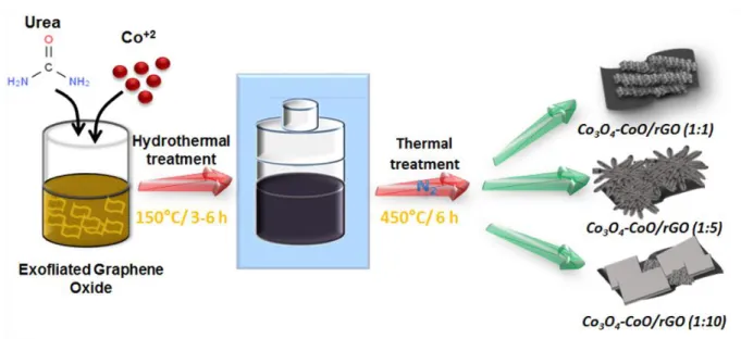
The preparation process for mesoporous Co3O4 mixed CoO onto reduced graphene oxide composites
is schematically depicted in Fig. 1. The in situ growth of cobalt oxide onto GO surface was realized via a hydrothermal reaction between urea and cobalt nitrate in the presence of GO, followed by thermal treatment under inert atmosphere. During the hydrothermal process, urea was decomposed by hydrolysis, forming ammonia and carbonate in the aqueous solution. These generated species react with cobalt cations Co2+ to form cobalt hydroxyl carbonate as mesoporous Co based precursor [25, 26]. The
cobalt oxide morphology can be easily tuned by controlling the precipitation of the corresponding precursors through varying the pH value governed by urea concentration [27]. The oxygen functionalities grafted onto GO surface (e.g., −COOH, −OH) act as ligands enabling the nucleation and growth of the cobalt oxide precursor, which leads to a strong affinity of the as-grown mesoporous cobalt carbonate and the GO surface [1, 18]. Besides, during the hydrothermal treatment, GO is chemically reduced to rGO. To avoid rGO combustion, the decomposition of cobalt carbonate at 450 °C was realized under inert atmosphere. Three Co(NO3)2;6H2O/CH4N2O molar ratios of 1:1, 1:5 and 1:10 were
used and denoted herein as Co3O4-CoO/rGO (1:1), Co3O4-CoO/rGO (1:5) and Co3O4-CoO/rGO (1:10),
respectively. The mass loading of carbon in the Co3O4-CoO/rGO composites was estimated by TG
analysis to be of ca. 40 wt% (Fig. S1), whatever the considered Co(NO3)2;6H2O/CH4N2O molar ratio.
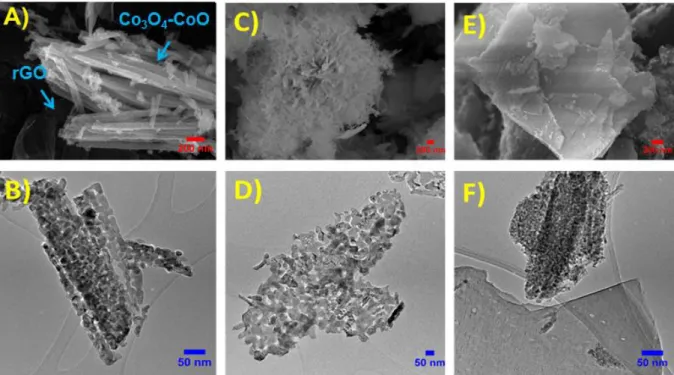
The surface morphology of the as-synthesized hybrid materials was examined by SEM and TEM (Fig. 2). The obtained images reveal that all samples possess hybrid nanostructure based on cobalt oxide nanoparticles assemblies deposited onto the rGO surface. The aggregation of these nanoparticles becomes more important with the increase of urea concentration, affecting the morphology of the cobalt
oxide deposit. Furthermore, representative low-magnification SEM images in (Fig. S2) clearly show that the shaped cobalt oxides are uniformly distributed onto the rGO surface with the absence of isolated rGO sheets. With low urea amount, the obtained hybrid material (Co3O4-CoO/rGO (1:1)) consists of
broom-like particles grown onto the rGO surface (Fig. 2A). This structure is a 2D self-assembled nanorods with a mean diameter of ca. 70 nm and lengths of ca. 2.5-4 μm. The TEM image shown in Fig. 2B indicates that these nanorods are stacked, and composed of closely connected nanoparticles with
ca. 28 nm average diameter. By decreasing the Co(NO3)2;6H2O/CH4N2O molar ratios to 1:5, cobalt
oxide with chrysanthemum-like morphology with sizes ranging from 8 to 25 μm was obtained (Fig. 2D). These 3D assemblies are formed by well-arranged nanorods, with ca. 50 nm diameters and lengths ranging from 0.3 to 1.2 μm. A closer look at TEM images (Fig. 2D) revealed that the oxide material is composed of highly coagulated nanocrystals with average size of ca. 21 nm, forming porous and interconnected cobalt oxide networks. At high urea amount Co3O4-CoO/rGO (1:10), the morphology of
cobalt oxide was quite different. Figure 2E shows the formation of micro-sized sheet-like structures consisting of superposed cobalt oxide nanoplates with different sizes. These 2D nanoplates are separated by rGO sheets to form a composite layered structure. The TEM image in (Fig. 2F) shows that the formed cobalt oxide nanoplates consist in uniformly distributed nanocrystals with ca. 11 nm average particle size. The EDS analyses of the Co3O4-CoO/rGO composites taken at different positions reveal that the
cobalt over oxygen ratio varies between 0.5 and 1.6 (Table S1), which is sound evidence that the three samples are composed of CoO and Co3O4.
The porous structure of these hybrid materials was studied by N2 sorption experiments. N2
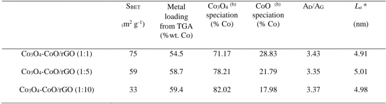
adsorption/desorption isotherms (Fig. S3) indicate that all samples display a type IV sorption isotherm with H4 hysteresis loop, characteristic of the presence of meso and micro-pores. The Brunauer–Emmett– Teller (BET) surface areas of Co3O4-CoO/rGO (1:1), (1:5) and (1:10) materials were found to be of ca.
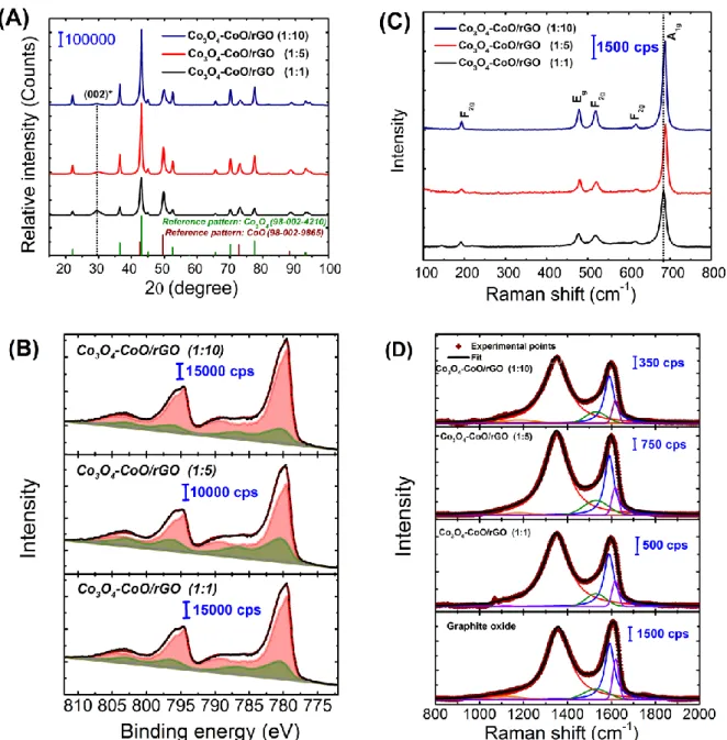
The crystalline structure and chemical composition of as-prepared samples were studied by X-ray diffraction (XRD), X-X-ray photoelectron (XPS) and Raman spectroscopy. The XRD patterns of the composites are shown in Fig. 3A. For all the samples, the observed X-ray lines can be readily indexed to be cubic spinel Co3O4 phase and rock salt cubic CoO phase according to the JCPDS card numbers
80-1544 and 48-1719, respectively. This confirms that the obtained cobalt oxide material consists in a mixture of Co3O4 and CoO. No evidence of any other crystalline phase could be observed. The
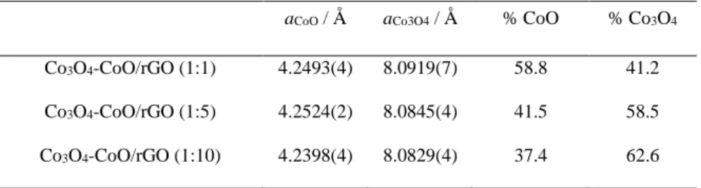
diffraction peak at ca. 31° is ascribed to graphitic plane (002) of the hexagonal lattice of reduced graphene oxide. Rietveld refinement of diffraction patterns was performed and allowed to obtain, among others, lattice parameters of cubic CoO (aCoO) and Co3O4 (aCo3O4) as well as phase quantification.
Results are shown in Table 1. Importantly, the amount of CoO phase is clearly found to be gradually rising as the urea amount decreases, suggesting the increase of the CoO phase amount on the hierarchical hybrid composites.
In order to obtain the surface composition of the Co3O4-CoO/rGO composites, X-ray
photoelectron spectroscopy (XPS) measurements were performed. The XPS survey spectra (Fig. S4) confirm that each material contains Co, O, C and N elements, without other detected impurities. It is important to note that the amount of nitrogen is very low and does not exceed 0.9 wt% for all samples. In Fig. 3B is depicted the high-resolution spectrum of Co 2p region obtained for the three studied cobalt oxide based composites. The binding energy of Co 2p3/2 and Co 2p1/2 photopeaksat 780.0 and 794.5 eV
with energy difference of 15.2 eV indicates the co-existence of Co2+ and Co3+ species on the surface of
the material [28]. Herein, the Co 2p spectra were processed and decomposed using two reference spectra corresponding to commercial Co3O4 (red curve) and CoO (green curve) materials [18, 29]. For all the
samples, the obtained spectra can be expressed as a linear combination of spectra recorded for these two reference materials, confirming therefore that the materials are composed of hybrids Co3O4-CoO. Based
on the decomposition of Co 2p region, the atomic percent of Co presenting a chemical environment representative of CoO and Co3O4 phases can be obtained. Thereby a surface molar ratio denoted as
Co3O4/CoO was calculated. As summarized in Table 2, the contribution of CoO at the surface becomes
results. However, whatever the composite material, the amount of the Co3O4 is always higher at the
surface as compared to the bulk composition.
To further probe information about composition of the catalysts, Raman spectroscopy is a great complement to the XPS and XRD analyses. The obtained spectra in the 200-800 cm-1 spectral region
(Fig. 2C), show five bands corresponding to the five Raman-active modes (A1g, Eg, and 3×F2g) expected
for a Co3O4 spinel structure [29, 30]. Besides, a barely visible broad contribution at about 500 cm-1,
characteristic of the CoO cubic rock salt structure, can also be observed in the spectra obtained for Co3O4-CoO/RGO (1:1) and Co3O4-CoO/RGO (1:5) composites. Furthermore, a small blue shift of the
Raman bands is observed depending on the urea concentration. The displacement towards higher Raman shifts of the A1g band as compared to Co3O4-CoO/RGO (1:1) is of about 4.6 and 5.5 cm-1 for Co3O4
-CoO/RGO (1:5) and (1:10), respectively. This shift of Raman bands position is also accompanied by an increase of the corresponding band intensity and a decrease of their full width at half maximum (FWHM) from 9.43 cm-1 for Co
3O4-CoO/RGO (1:1) sample to 7.09 and 6.67 cm-1 for Co3O4-CoO/RGO (1:5) and
(1:10), respectively. The above-mentioned changes indicate that the vibration mode of the Co-O bonds changes for composites prepared at higher urea concentrations. Riva-Murias et al. have established that the conversion of rock salt CoO phase into the spinel Co3O4 phase is accompanied by an increase of the
peaks intensity and a decrease of their corresponding width [31, 32]. The obtained spectra reveal the increase of the Co3O4 amount, and consequently, the decrease of that of CoO for higher urea
concentrations. On the other hand, the slight shift observed for the A1g band could be explained by the
different interactions with the substrate. Indeed, from TEM observations, it can be suggested that the decrease of CoO contribution could be linked to the interaction between the cobalt oxide and the GO substrate, which is more important at higher urea concentration. In fact, the increase of urea concentration leads to a diminution of the oxide nanoparticles size and limits therefore their superposition effect, promoting their growth onto the GO substrate. In addition, it should be considered that the presence of oxygenated functional groups on GO plays a role in the oxidation of CoO to Co3O4
during the thermal treatment allowing the conversion of cobalt carbonate to cobalt oxide, this role should be more important with the dense-interconnected oxide/carbon composites at higher urea concentration.
To go further, the obtained Raman spectra of the carbonaceous spectral region are shown in Fig. 2D. Their decomposition was performed considering five bands [33, 34]: two Lorentzian lineshapes located at ca. 1350 cm-1 (D-band) and 1590 cm-1 (G-band) [35, 36] and three Gaussian lineshapes
centred at ca. 1180 cm-1 (D*-band) [37], 1530 cm-1 (D′′-band) [35] and 1620 cm-1 (D′-band) [38]. The D
mode is a defect-induced one associated with the disruption of the C=C ring structure [39]. The G mode is attributed to first-order scattering of the E2g mode [40]. The D’’ mode can be associated with the
presence of amorphous sp2 phase [41, 42]. The peak centred at 1180 cm-1 is ascribed to the presence of
polyene like [34]. Finally, the D’ band can be appropriate to the intercalation of compounds in the graphitic lattice [43].
𝐿𝑎(nm) = 2.4 × 10⁻¹⁰× 𝜆laser4 × AG
AD (3)
The graphitization degree, evaluated from the area ratio of D (red line) to G (blue line), denoted as AD/AG [43], was of ca. 3.4 for all samples, showing a very slight increase compared with the value of
about ca. 3.2 obtained for GO substrate. This ratio is used to quantify the amount of defects and to calculate the in-plane crystallite size (La) (equation 3). According to calculated La values reported in
Table 2, the in-plane crystallite sizes slightly increase after cobalt oxide deposition. This indicates that even if defects and particularly holes are formed in the carbon matrix during the oxidation process of graphite, they remain after deposition of shaped cobalt oxide. Besides, from the calculated La values it
can be stated that the in-plane crystallite size values are not affected by the urea concentration in the reaction mixture. Finally, it is important to note that the XPS can probe only a few atomic layers, and thus the analysis of the rGO substrate after cobalt deposition by XPS was not possible.
1.1. Electrochemical characterization of electrocatalysts
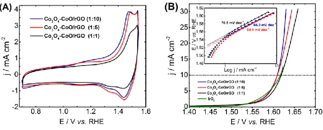
The electrochemical behavior of the as-prepared catalysts was first investigated by cyclic voltammetry in a N2-saturated 1 mol L-1 KOH electrolyte at a scan rate of 20 mV s-1. As shown in Fig.
4A, the recorded voltammograms of the electrode materials display two anodic peaks assigned to the CoII/CoIII (1.05-1.25 V vs RHE) and CoIII/CoIV (1.45-1.5 V vs RHE) redox transitions, respectively
coulometry associated with these two redox peaks is less pronounced for Co3O4-CoO/rGO (1:1). This
can be attributed to a lack of electronic conductivity in reason of the overlay of cobalt oxide particle and the low surface contact between oxide phase and carbon substrate. Furthermore, the anodic wave corresponding to CoIII/CoIV redox transition shifts towards positive potential values with the decrease of
urea concentration of about ca. 10 and 30 mV for Co3O4-CoO/rGO (1:5) and Co3O4-CoO/rGO (1:1),
respectively, as compared to the peak position of Co3O4-CoO/rGO (1:10). This shift can be directly
related to the surface enrichment with octahedral CoIII species in agreement with the increase of the
Co3O4 amount contribution at higher urea amount. To gain more insight in these electrochemical surface
changes, the ECSA of each electrode material was calculated from the electrochemical double layer capacitances by using Equation (4) hereafter.
ECSA = Cdl / Cs (4)
where Cdl is electrochemical double layer capacitance calculated from the CV plots recorded at
non-Faradaic potential regions 0.9 – 1.1 V vs. RHE at various scan rates (10 to 50 mV s-1), the ECSA values
is the slope value of the fitting lines from the anodic intensity at 0.95 V vs. RHE against the CV scan rates (Fig. S5). The specific capacitance Cs (40 μF cm−2) is the average double-layer capacitance. The
Cdl values for Co3O4-CoO/rGO (1:1), (1:5) and (1:10) catalysts are of ca. 219, 455 and 496 μF,
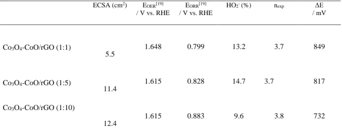
respectively. The corresponding ECSA values are of 5.5, 11.4 and 12.4 cm2. This suggests that the
catalysts prepared with high urea concentration with sheet-like and chrysanthemum-like structures have more exposed electroactive surface compared to broom-like structure, indicating that the dense-interconnected oxide/carbon favors the interfacial electrochemical reactions between the electrocatalyst and electrolyte. The electrocatalytic activity of the Co3O4-CoO/rGO nanocomposites towards OER was
investigated by linear sweep voltammetry in an O2-saturated 1 mol L-1 KOH electrolyte (Fig. 4B). From
potential values to drive a current density of 10 mA cm-2 (Table 2), one can conclude that the increase
of the amount of Co3O4 phase in the composite material leads to improved activity towards OER, which
becomes slightly higher than that of the IrO2 reference catalyst. This enhanced activity is attributed to
the higher amount of CoIII surface species for the catalysts prepared with the highest urea amount which
insights on OER kinetics at the surface of the nanocomposites, Tafel slopes were extracted from the Tafel plots (Fig. 4B). For all composites, the Tafel slope values are in the range of 65-70 mV dec-1.
These values suggest that OER process at the surface of the different catalysts follows the same mechanism with the first electron transfer being the rate limiting step, suggesting that Co3O4 is the main
active phase in this reaction [47].
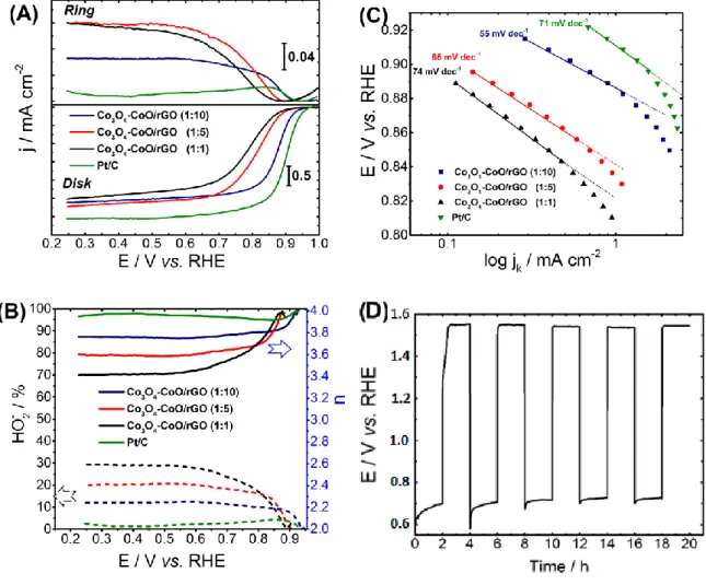
Rotating ring-disk electrode (RRDE) measurements were carried out to determine the electrocatalytic activity towards ORR as well as the selectivity of this process towards hydroxyl ions in O2-saturated alkaline electrolytes (Fig. 5A). The potential values to drive a current density of -1 mA cm -2 as activity indicator, peroxide production percentage and electron transfer number (n
exp) for the
nanocomposites catalysts at various urea amounts are reported in Table 3. From these results, it can be seen that the increase of the urea concentration during the composite synthesis leads to an increase of the electroactivity towards the ORR. This trend can be linked to the interfacial oxide–carbon interaction, enhancing the charge transfer of the Co3O4-CoO/rGO composite and therefore its activity towards ORR.
Besides, the sheet-like structure with Co3O4-CoO/rGO (1:10) makes the interface oxide-carbon sites
more accessible compared to the broom-like and chrysanthemum-like morphologies. Catalytic performances close to those of the commercial Pt/C catalyst were obtained for Co3O4-CoO/rGO (1:10).
On the other hand, the increase of oxide-oxide interface causing a lack of electronic conductivity at lower urea amount modifies the adsorption energies of reaction intermediates involved in the ORR process and consequently the nature of the ORR rate-determining step. This is confirmed by Tafel slope values (Fig. 5C), which increased from 55 mV.dec-1 for Co
3O4-CoO/rGO (1:10) to 65 and 75 mV.dec-1
for Co3O4-CoO/rGO (1:5) and (1:1), respectively. The percentage of peroxide species formed with
respect to total oxygen reduction products as well as the number of electrons exchanged per oxygen molecule (nexp) were determined from measured disk and ring currents, suggesting that the reaction
implies a mixed 4e- and 2e- reduction mechanism, with a predominance of the 4-electron pathway.
Results are shown in Fig. 5B and summarized in Table 3. The yield of peroxide species formed during the reduction process remains below 14% for all samples. This corresponds to electron transfer number
of about 3.7-3.8 at 0.80 V vs. RHE. In order to evaluate the ability of such catalyst as an air electrode, stability tests were carried out by alternatively performing OER and ORR at the catalyst surface. The most active and stable composite catalyst Co3O4-CoO/rGO (1:10) was selected for this test. The test was
carried out in a 8 mol L-1 KOH electrolyte by alternatively applying a current density of -20 mA cm-2
during 2 h and a current density of 20 mA cm-2 during 2 h. Results are shown in (Fig. 5D). It can be
observed that there is no activity loss for both OER and ORR processes. Indeed, the electrode potential difference between ORR and OER is initially of ca. 827 mV and it is of 817 mV after 20 h testing.
Conclusion
Mesoporous cobalt oxide onto rGO nanocomposites were obtained by an easy surfactant-free synthesis route. TEM and SEM analyses revealed that the three obtained materials possess cobalt-based nanostructures uniformly deposited onto rGO. Furthermore, it was shown that the concentration of urea during the synthesis enabled tuning the morphology of the obtained cobalt-based nanostructures: broom-like, chrysanthemum-like and micro-sized sheet-like morphologies were obtained when increasing the urea amount. The physical characterizations of these composite materials revealed that the obtained cobalt oxide material consists in a mixture of Co3O4 and CoO phases. Rietveld refinement of diffraction
patterns allowed obtaining, among others, lattice parameters of cubic CoO (aCoO) and Co3O4 (aCo3O4) as
well as phase quantification in the three obtained composite materials. The amount of CoO phase was clearly found to be gradually rising as the urea amount decreases. This increase of the CoO phase was also observed by XPS even if whatever the composite material, the amount of the Co3O4 is always higher
at the surface as compared to the bulk composition. Raman spectra further confirmed the increase of the Co3O4 amount and consequently, the decrease of that of CoO for higher urea concentrations and bring
to light different interactions with the substrate suggesting that the decrease of CoO amount could be linked to the interaction between the cobalt oxide and the rGO substrate, which is more important at higher urea concentration. In fact, the increase of urea concentration leads to a diminution of the oxide nanoparticles size and limits therefore their superposition effect, promoting their growth onto the GO substrate.
The electrochemical characterizations showed that the catalysts prepared at high urea concentrations (sheet-like and chrysanthemum-like morphologies) have more exposed electroactive surface compared to broom-like structure, indicating that the dense-interconnected oxide/carbon favors the interfacial electrochemical reactions between the electrocatalyst and electrolyte.
The electrocatalytic activity of the Co3O4-CoO/rGO nanocomposites towards OER was found to be
improved with the increase of the amount of Co3O4 phase in the composite material, becoming slightly
higher than that of the IrO2 reference catalyst for the two composite materials prepared at high urea
concentrations. This enhanced activity is attributed to the higher amount of CoIII surface species for
these catalysts, which promotes the formation of electroactive CoVI sites at lower potential. The
calculated Tafel slope values (in the 65-70 mV dec-1 range) indicated that OER process at the surface of
the different catalysts follows the same mechanism with the first electron transfer being the rate limiting step, confirming that the Co3O4 are the main active species in this reaction.
The increase of the urea concentration during the composite synthesis also leads to an increase of the electroactivity towards the ORR. This trend can be linked to the interfacial oxide–carbon interaction, enhancing the charge transfer of the Co3O4-CoO/rGO composite and therefore its electroactivity towards
ORR. Catalytic performances close to those of the commercial Pt/C catalyst were therefore obtained for the catalyst prepared with the highest urea amount, Co3O4-CoO/rGO (1:10). The increase of oxide-oxide
interface at lower urea amount causes a lack of electronic conductivity modifying the adsorption energies of reaction intermediates involved in the ORR process and consequently the nature of the ORR rate-determining step. This is confirmed by calculated Tafel slope values that increased from 55 mV.dec -1 for Co
3O4-CoO/rGO (1:10) to 65 and 75 mV.dec-1 for Co3O4-CoO/rGO (1:5) and (1:1), respectively.
The yield of peroxide species formed during the reduction process remains below 14% for the three catalysts, which corresponds to an electron transfer number between 3.7 and 3.8 at 0.80 V vs. RHE, suggesting that the reaction implies a mixed 4e- and 2e- reduction mechanism, with a predominance of
the 4-electron pathway.
In addition, the most active composite catalyst Co3O4-CoO/rGO (1:10) was shown to be very stable as
reversibility criterion (difference between the potential value required to reach 20 mA cm-2 during OER
in at 8 mol L-1 KOH electrolyte.
In conclusion, the composite materials obtained by the proposed easy surfactant-free synthesis route and specially the Co3O4-CoO/rGO (1:10) one are very promising candidates for the elaboration of a stable
and truly reversible air electrode in alkaline media for energy conversion and storage devices.
Acknowledgement
This work was supported by the Agence Nationale de la Recherche (ANR), project E Air (ANR-14-CE05-0036-01). IA is grateful for this financial support (PhD grant). This work was developed within the scope of the project CICECO-Aveiro Institute of Materials, FCT Ref. UID/CTM/50011/2019, financed by national funds through the FCT/MCTES. PF thanks FCT for the grant IF/00300/2015.
References
[1] Z.-F. Huang, J. Wang, Y. Peng, C.-Y. Jung, A. Fisher, X. Wang, Adv Energy Mater, 1700544 (2017).
[2] L. Li, Z.-w. Chang, X.-B. Zhang, Adv Sustain Syst, 1700036 (2017). [3] R. Cao, J.-S. Lee, M. Liu, J. Cho, Adv Energy Mater, 2, 816 (2012).
[4] B. Zhang, F. Guo, L. Yang, X. Jia, B. Liu, Z. Xie, D. Chen, H. Lu, R. Zhang, Y. Zheng, J Cryst
Growth, 459, 167(2017).
[5] Q. Zhao, Z. Yan, C. Chen, J. Chen, Chem Rev, 117, 10121 (2017).
[6] H. Wang, Y. Yang, Y. Liang, G. Zheng, Y. Li, Y. Cui, H. Dai, Energy Environ Sci, 5, 7931 (2012). [7] S.V.P. Vattikuti, C. Byon, C.V. Reddy, Mater Res Bull, 75, 193 (2016).
[8] L. Han, S. Dong, E. Wang, Adv Mater, 28, 9266 (2016).
[9] N.T. Suen, S.F. Hung, Q. Quan, N. Zhang, Y.J. Xu, H.M. Chen, Chem Soc Rev, 46, 337 (2017). [10] J. Chen, X. Wu, A. Selloni, Phys Rev B, 83 (2011).
[11] C. Goswami, K.K. Hazarika, P. Bharali, Mater Sci Energy Technol, 1, 117(2018). [12] C. Zhu, H. Li, S. Fu, D. Du, Y. Lin, Chem Soc Rev, 45, 517-531 (2016).
[13] A. Ambrosi, C.K. Chua, A. Bonanni, M. Pumera, Chem Rev, 114, 7150 (2014). [14] S. Mao, Z. Wen, T. Huang, Y. Hou, J. Chen, Energy Environ Sci, 7, 609(2014).
[15] K. Kumar, C. Canaff, J. Rousseau, S. Arrii-Clacens, T.W. Napporn, A. Habrioux, K.B. Kokoh, J
Phys Chem C, 120, 7949 (2016).
[16] Y.Y. Liang, Y.G. Li, H.L. Wang, J.G. Zhou, J. Wang, T. Regier, H.J. Dai, Nat Mater, 10, 780 (2011).
[17] Y. Liang, H. Wang, J. Zhou, Y. Li, J. Wang, T. Regier, H. Dai, J Am Chem Soc, 134, 3517 (2012).
[18] K. Kumar, I. Abidat, C. Canaff, A. Habrioux, C. Morais, T.W. Napporn, K.B. Kokoh,
ChemElectroChem, 5, 483 (2018).
[19] I. Abidat, E. Cazayus, L. Loupias, C. Morais, C. Comminges, T.W. Napporn, D. Portehault, O. Durupthy, A.-S. Mamede, C. Chanéac, J.-F. Lamonier, A. Habrioux, K.B. Kokoh, J Electrochem Soc, 166, H94 (2019).
[20] J. Duan, S. Chen, M. Jaroniec, S.Z. Qiao, ACS Catalysis, 5, 5207 (2015). [21] T.Y. Ma, S. Dai, M. Jaroniec, S.Z. Qiao, J Am Chem Soc, 136, 13925 (2014). [22] D.U. Lee, B.J. Kim, Z. Chen, J Mater Chem A, 1, 4754 (2013).
[23] J.B. Aladekomo, R.H. Bragg, Carbon, 28, 897 (1990).
[24] U.A. Paulus, T.J. Schmidt, H.A. Gasteiger, R.J. Behm, J Electroanal Chem, 495, 134 (2001). [25] T.M. Masikhwa, J.K. Dangbegnon, A. Bello, M.J. Madito, D. Momodu, F. Barzegar, N. Manyala,
J Phys Chem Solids, 94, 17 (2016).
[27] M. Roy, S. Ghosh, M.K. Naskar, Dalton Trans, 43, 10248 (2014).
[28] C. Su, W. Wang, Y. Chen, G. Yang, X. Xu, M.O. Tade, Z. Shao, ACS Appl Mater Interfaces, 7, 17663 (2015).
[29] I. Abidat, C. Morais, C. Comminges, C. Canaff, J. Rousseau, N. Guignard, T.W. Napporn, A. Habrioux, K.B. Kokoh, J Mater Chem A, 5, 7173 (2017).
[30] V.G. Hadjiev, M.N. Iliev, I.V. Vergilov, J Phys C: Solid State Phys, 21, L199 (1988). [31] J. Ren, Z. Wang, F. Yang, R.-P. Ren, Y.-K. Lv, Electrochim Acta, 267, 133 (2018). [32] B. Rivas-Murias, V. Salgueirino, J Raman Spectrosc, 48, 837 (2017).
[33] R. Hawaldar, P. Merino, M.R. Correia, I. Bdikin, J. Gracio, J. Mendez, J.A. Martin-Gago, M.K. Singh, Sci Rep, 2, 682 (2012).
[34] S. Claramunt, A. Varea, D. López-Díaz, M.M. Velázquez, A. Cornet, A. Cirera, J Phys Chem C, 119, 10123 (2015).
[35] T. Jawhari, A. Roid, J. Casado, Carbon, 33, 1561 (1995).
[36] E.F. Antunes, A.O. Lobo, E.J. Corat, V.J. Trava-Airoldi, A.A. Martin, C. Veríssimo, Carbon, 44 2202 (2006).
[37] X.M. Tang, J. Weber, S.N. Mikhailov, C. Müller, W. Hänni, H.E. Hintermann, J Non-Cryst
Solids, 185, 145 (1995).
[38] V. Mennella, G. Monaco, L. Colangeli, E. Bussoletti, Carbon, 33, 115 (1995).
[39] D. Yang, A. Velamakanni, G. Bozoklu, S. Park, M. Stoller, R.D. Piner, S. Stankovich, I. Jung, D.A. Field, C.A. Ventrice, R.S. Ruoff, Carbon, 47, 145 (2009).
[40] F. Tuinstra, J.L. Koenig, J Chem Phys, 53, (1970) 1126-1130. [41] M. Veres, S. Tóth, M. Koós, Diamond Relat Mater, 17, 1692 (2008).
[42] L.G. Cancado, A. Jorio, E.H. Ferreira, F. Stavale, C.A. Achete, R.B. Capaz, M.V. Moutinho, A. Lombardo, T.S. Kulmala, A.C. Ferrari, Nano Lett, 11, 3190 (2011).
[43] I. Abidat, C. Morais, S. Pronier, N. Guignard, J.D. Comparot, C. Canaff, T.W. Napporn, A. Habrioux, A.S. Mamede, J.F. Lamonier, K.B. Kokoh, Carbon, 111, 849 (2017).
[44] J.Y. Lee, T.C. Tan, Cyclic Voltammetry of Electrodeposition of Metal on Electrosynthesized Polypyrrole Film, J Electrochem Soc, 137, 1402 (1990).
[45] H.Y. Wang, S.F. Hung, H.Y. Chen, T.S. Chan, H.M. Chen, B. Liu, J Am Chem Soc, 138, 36 (2016).
[46] A. Bergmann, E. Martinez-Moreno, D. Teschner, P. Chernev, M. Gliech, J.F. de Araujo, T. Reier, H. Dau, P. Strasser, Nat Commun, 6, 8625 (2015).
Figures
Fig. 1: Schematic illustration of the fabrication of mesoporous Co3O4 mixed CoO onto reduced
graphene oxide composites by hydrothermal approach followed by heat treatment at 450 °C under N2
Fig. 2: SEM images (A, C, E) and TEM images (B, D, F) of the Co3O4-CoO/rGO nanocomposites: A
Fig. 3 A) Powder X-ray diffraction patterns of as-prepared hybrid Co3O4-CoO/rGO, B) High resolution
XPS spectrum of Co 2p region of the Co3O4-CoO/rGO composites. The reference spectra obtained with
CoO and Co3O4 and used for the decomposition are respectively green and red curves. The simulations
envelops are black curves. C) Cobalt region and D) carbon region of the Raman spectra recorded in the different Co-based nanocomposites.
Fig. 4. (A) Cyclic voltammograms of the Co3O4-CoO/RGO electrodes in 1 M KOH media at scan rate
of 20 mV s-1. (B) OER polarization curves obtained at 1600 rpm at a scan rate of 5 mV s-1 in O
2-saturated
1 M alkaline electrolytes on the Co3O4-CoO/RGO composites (Inset Fig. Tafel plots for the different
Fig. 5 (A) ORR polarization curves recorded with the different composites using a RRDE. These curves were recorded in an O2-saturated 1 mol L-1 KOH solution at a scan rate of 5 mV s-1, at 25 °C and at a
rotation rate of 1600 rpm. The ring is polarized at 1.2 V vs. RHE during the experiment. jR and jD are
currents densities measured with the ring electrode and the disk electrode, respectively. The catalyst loading is ca. 0.2 mg cm-2 (B) Calculated peroxide yield and electron transfer number (n
exp) exchanged
per oxygen molecule on the basis of RRDE electrochemical data. (c) Tafel plots of all samples. (D) Cycling stability test performed with Co3O4-CoO/rGO catalyst by alternatively applying a current
density of -20 mA cm-2 during 2 h and a current density of 20 mA cm-2 during 2 h. The test is performed
Table 1: Lattice parameter values of Co3O4 (aCo3O4) and CoO (aCoO) phases as well as mass phase
composition in the different composites
aCoO / Å aCo3O4 / Å % CoO % Co3O4
Co3O4-CoO/rGO (1:1) 4.2493(4) 8.0919(7) 58.8 41.2
Co3O4-CoO/rGO (1:5) 4.2524(2) 8.0845(4) 41.5 58.5
Table 2. Summary of important parameters of the different composite materials. SBET (m2 g-1) Metal loading from TGA (%wt. Co) Co3O4(b) speciation (% Co) CoO (b) speciation (% Co) AD/AG La * (nm) Co3O4-CoO/rGO (1:1) 75 54.5 71.17 28.83 3.43 4.91 Co3O4-CoO/rGO (1:5) 59 58.7 78.21 21.79 3.35 5.01 Co3O4-CoO/rGO (1:10) 33 59.4 82.02 17.98 3.37 4.98
(a) Co atoms in a chemical environment with an electronic density similar to the one encountered in CoO phase (b) Co atoms in a chemical environment with an electronic density similar to the one encountered in Co3O4 phase
Table 3. ORR and OER activities for different catalysts measured in 1 M KOH at a rotation rate of 1600 rpm. ECSA (cm2) E OER[19] / V vs. RHE EORR[19] / V vs. RHE HO2- (%) nexp ΔE / mV Co3O4-CoO/rGO (1:1) Co3O4-CoO/rGO (1:5) Co3O4-CoO/rGO (1:10) 5.5 11.4 12.4 1.648 1.615 1.615 0.799 0.828 0.883 13.2 14.7 9.6 3.7 3.7 3.8 849 817 732 [19] potential at 10 mA cm-2; [19] potential at -1 mA cm-2; [19] E OER-EORR