Publisher’s version / Version de l'éditeur:
Vous avez des questions? Nous pouvons vous aider. Pour communiquer directement avec un auteur, consultez la
première page de la revue dans laquelle son article a été publié afin de trouver ses coordonnées. Si vous n’arrivez pas à les repérer, communiquez avec nous à PublicationsArchive-ArchivesPublications@nrc-cnrc.gc.ca.
Questions? Contact the NRC Publications Archive team at
PublicationsArchive-ArchivesPublications@nrc-cnrc.gc.ca. If you wish to email the authors directly, please see the first page of the publication for their contact information.
https://publications-cnrc.canada.ca/fra/droits
L’accès à ce site Web et l’utilisation de son contenu sont assujettis aux conditions présentées dans le site LISEZ CES CONDITIONS ATTENTIVEMENT AVANT D’UTILISER CE SITE WEB.
Fire and Materials, 10th International Conference [Proceedings], pp. 1-17,
2007-01-29
READ THESE TERMS AND CONDITIONS CAREFULLY BEFORE USING THIS WEBSITE.
https://nrc-publications.canada.ca/eng/copyright
NRC Publications Archive Record / Notice des Archives des publications du CNRC :
https://nrc-publications.canada.ca/eng/view/object/?id=57b1204e-283b-4c94-97a2-7d3d4818e37a https://publications-cnrc.canada.ca/fra/voir/objet/?id=57b1204e-283b-4c94-97a2-7d3d4818e37a
Archives des publications du CNRC
This publication could be one of several versions: author’s original, accepted manuscript or the publisher’s version. / La version de cette publication peut être l’une des suivantes : la version prépublication de l’auteur, la version acceptée du manuscrit ou la version de l’éditeur.
Access and use of this website and the material on it are subject to the Terms and Conditions set forth at
Gypsum board fall-off in floor assemblies exposed to a standard fire
G y p s u m b o a r d f a l l - o f f i n f l o o r a s s e m b l i e s
e x p o s e d t o a s t a n d a r d f i r e
N R C C - 4 5 4 2 0
E l e w i n i , E . ; S u l t a n , M . A . ; H a d j i s o p h o c l e o u s ,
G . V .
A version of this document is published in / Une version de ce document se trouve dans: Fire and Materials, 10th International Conference, San Francisco, Jan. 29, 2007, pp. 1-15
The material in this document is covered by the provisions of the Copyright Act, by Canadian laws, policies, regulations and international agreements. Such provisions serve to identify the information source and, in specific instances, to prohibit reproduction of materials without written permission. For more information visit http://laws.justice.gc.ca/en/showtdm/cs/C-42
Les renseignements dans ce document sont protégés par la Loi sur le droit d'auteur, par les lois, les politiques et les règlements du Canada et des accords internationaux. Ces dispositions permettent d'identifier la source de l'information et, dans certains cas, d'interdire la copie de documents sans permission écrite. Pour obtenir de plus amples renseignements : http://lois.justice.gc.ca/fr/showtdm/cs/C-42
Exposed to a Standard Fire
Eman Elewini1, Mohamed A. Sultan2 and George V. Hadjisophocleous1
1 Department of Civil and Environmental Engineering, Carleton University, Ottawa, Canada K1S 5B6 2 Institute for Research in Construction, National Research Council of Canada, Ottawa, Canada K1A 0R6
ABSTRACT
This paper presents and discusses the results of gypsum board fall-off time in 80 full-scale fire resistance floor test assemblies using lightweight framed wood joists, wood-I joists and steel joists and wood trusses, protected with either one or two layers of Type X gypsum board. The effects of a number of assembly parameters such as: the number of gypsum board layers; resilient channels installation and spacing; insulation installation and frame type on the gypsum board fall-off time are presented. A comparison of the fire resistance and gypsum board fall-off time for floor assemblies protected with either one or two layers of Type X gypsum board is also presented.
INTRODUCTION
With the advent of performance-based codes and performance-based fire safety design options, the development of fire resistance models becomes essential. Development of such models faces several challenges such as the availability of reliable thermal and mechanical properties of materials at elevated temperatures and gypsum board fall-off time in lightweight framed assemblies. The gypsum board can provide up to 90% of fire resistance protection as it contains 21% of free and crystallized water. The understanding of gypsum board performance in protecting lightweight framed assemblies is essential in the development of acceptable and realistic fire resistance models.
The Institute for Research in Construction of the National Research Council of Canada (NRC-IRC), in collaboration with industry and government partners, carried out two major experimental research studies
(Floors-I1 and Floors-II2) to measure the fire resistance and acoustic performance of full-scale floor
assemblies with different frames including the wood joists, wood I- joists, steel C-joists and wood trusses. Details on the assemblies’ construction and fire resistance results of these studies can be found in References 1 and 2. This study on the gypsum board fall-off time (based on the data collected in References 1 and 2) was carried out jointly between NRC-IRC and Carleton University based on the data collected in the Floors-I and Floors-II studies. Gypsum board fall-off times were determined from test observations and video-recording cameras of the fire-exposed gypsum board surfaces. The effects on the gypsum board fall-off time of a number of parameters such as the number of gypsum board layers, resilient channels installation and spacing, insulation installation and type and framing type are present in this paper. Details on the effects of other parameters on the fall-off time can be found in Reference 3.
Gypsum Board
Gypsum board is a product that provides significant fire resistance protection to building assemblies. It is in a form of a sheet product that consists of a non-combustible core, that pounded with paper-laminated surfaces, which is at least 75% pure gypsum with up to 25% additives such as glass fibre and vermiculate as well as other materials to enhance the fire resistance performance by reducing the likelihood of crack propagations and board shrinkage when exposed to heat. The gypsum core is calcium sulphate dehydrate,
CaSO4 .2H2 O, a crystalline mineral that contains about 21% by weight chemically combined water. In
addition, gypsum usually contains a small amount of absorbed free water. As the gypsum is heated to a temperature in excess of 80°C, it begins to undergo a thermal degradation process known as calcinations, in which the chemically combined water dissociates from the crystal lattice. The chemical equation for this process is
CaSO4 .2H O2 → CaSO4 ½ H2 O + 3/2 H2 O
Calcium sulphate hemihydrate (CaSO4 ½ H2 O + 3/2 H2 O) is commonly known as plaster of Paris. As
the gypsum core reaches 125°C, calcinations are usually complete. Through continued heating, the remaining water is released as the hemihydrate undergoes dehydration to form anhydrous calcium
sulphate CaSO4.
DESCRIPTION OF TEST ASSEMBLIES
Eighty floor assemblies, 4.8 m long by 3.9 m wide, were constructed in accordance with
CAN/CSA-A82.31-M914. Floor framing consisted of solid wood, wood I-, steel C- joists and wood
trusses. In 72 floor assemblies (see Table 1) resilient channels, spaced either 203 mm or 406 mm o.c. or 610 mm o.c., were used and attached perpendicular to either the joists or trusses to support the gypsum board ceiling finish. Additional resilient channels were also installed to support gypsum board ends (board short dimension). The resilient channels, 14 mm deep by 58 mm wide, were fabricated from 0.6 mm thick galvanized steel sheets. The channels had a 34 mm wide web, designed to support the gypsum board connection, and one 18 mm wide flattened flange lip connected to the bottom of the joists or trusses. Three types of insulation were used: glass and rock fibre batts, and cellulose fibre insulation either sprayed wet on the underside of the sub-floor and on the side of the joists and allowed to dry to achieve an 11% moisture content or dry blown and supported at the bottom of the joists or trusses with a steel mesh.
The glass, rock and cellulose insulation satisfied CSA A101-M835, CAN/ULC S702-M976 and CGSB
51.60-M907, respectively. The resilient channels and insulation were used for acoustical purposes to
reduce the sound transmission across the floor. The sub-floor types used in the assemblies were either Canadian Softwood Plywood (CSP) or steel deck with concrete topping. The ceiling finish used in the assemblies was Type X gypsum board, 12.7 mm and 15.9 mm thick. The gypsum board used had the
Firecode C Core Type X designation and met the requirements of Type X gypsum board8,9. The gypsum
boards were supplied from one manufacturer to minimize potential variability associated with the production of such material by different producers. The boards were also packaged (100 boards) to avoid board damage in transportation from the manufacturer to the NRC-IRC laboratories. The gypsum boards
had an average surface density of 9.85 kg/m2 and 10.5 kg/m2 for a nominal 12.7 mm and 15.9 mm thick
board. The gypsum boards were attached perpendicular to either resilient channels in 72 assemblies or directly to the framing in 8 assemblies. Table 1 lists the variable parameters of the assemblies studied. Complete construction details can be found in References 1 and 2.
INSTRUMENTATION
In addition to the standard instrumentation specified in CAN/ULC-S101-M8910, numerous
thermocouples were placed within each floor assembly in order to obtain temperature histories at various locations during fire tests. Type K (20 gauge) chromel-alumel thermocouples, with a thickness of 0.91 mm, were used for measuring the temperatures of the sub-floor surface and gypsum board surface facing the floor cavity as well as the interface surface between the gypsum board for assemblies with two layers of gypsum board and between the gypsum board and insulation at the floor cavity side. Also, additional instrumentation to measure the deflection of the sub-floor was used at 9 locations: 3 along the centre line of the assembly and 3 on each side of the centre line at equal spacing. Details on the locations of the thermocouples and deflection gauges can be found in References 1 and 2. All floor assemblies were tested with a superimposed load depending on the components of the assembly. Assemblies FF-01A to
FF-09 were tested using a restricted load of 75% of maximum design load; however, assemblies FF-10 to FF-82 were tested on a maximum design load. Details on the loading system arrangement can be found in References 1 and 2. The superimposed load used in this study for each assembly is given in Table 1. Two video cameras were used to record the fire exposed gypsum board performance observations.
TEST CONDITIONS AND PROCEDURE
The assembly’s gypsum board ceiling finish was exposed to heat in a propane-fired horizontal
furnace, shown in Figure 1, in accordance with CAN/ULC-S101-M8910, “Standard Methods of Fire
Endurance Tests of Building Construction and Materials” which is similar to ASTM E11911 “Standard
Test Method for Fire Tests of Building Construction and Materials”. The furnace temperature was measured by nine (20 gauge) shielded thermocouples and the average of these thermocouples was used to control the furnace temperature in such a way that it followed, as closely as possible, the CAN/ULC-S101-M89 standard temperature-time curve.
The assembly was considered to have failed if one of the following failure criteria as per CAN/ULC-S101-M89 Standard, occurred first:
1. A single point temperature reading measured by one of the nine thermocouples under insulation on the unexposed surface rose 180°C above the ambient temperature,
2. The average temperature measured by the 9 thermocouples under the insulated pads on the unexposed surface rose 140°C above the ambient temperature,
3. There was passage of flame or gases hot enough to ignite cotton waste, and 4. The assembly is no longer able to bear the applied load.
RESULTS AND DISCUSSION
The results of the 80 full-scale fire resistance floor tests are summarised in Table 1 in which the fire resistance and gypsum board layers off time are provided for each assembly. The gypsum board fall-off was not discussed for all assemblies in Table 1 but provided for readers’ convince. The average temperatures at different surfaces in each assembly, furnace average temperature and three deflection measurements (maximum deflections) at the centre line of the assembly can be found in References 1 and 2.
Effect of Number of Gypsum Board Layers on Fall-Off Time
Ten floor assemblies (5 with one layer and the other 5 with two layers of gypsum board) were examined to investigate the effect of adding an additional layer of gypsum board to assemblies with one layer on the board fall-off time for assemblies with different types of joist.
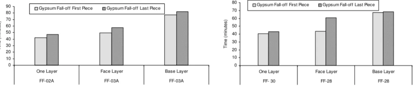
Assemblies with solid wood joists: The fall-off time for the first and last pieces of gypsum board in assemblies FF-02A and FF-03A is shown in Figure 1. For the assembly protected with a single layer of gypsum board, FF-02A, the first and last pieces of gypsum board fell-off at around 42 and 47 minutes while for the assembly FF-03A, protected with two layers of gypsum board, the first and last pieces of the face layer of gypsum board fell-off around 49 and 57 minutes, respectively. The fall-off time of the face layer’s first and last piece in the assembly with two layers of gypsum board was larger than in the assembly with one layer of gypsum. This could be a result of the heat absorbed by the gypsum board base layer when its free and molecular bound water was driven off from the core. After the fall-off of the first piece of the face layer, the frame in assembly FF-03A was still protected by the base layer until the fall-off of its first piece at around 77 minutes. This shows that adding a second layer of gypsum board had provided an additional 35 minutes protection to the frame and delayed the fall-off of the gypsum board layer exposed to furnace heat than in an assembly with only one layer of gypsum board.
Also, a comparison for the fall-off time of gypsum board layers for two more assemblies, 30 and FF-28, is shown in Figure 2. The first and last pieces of gypsum board, Assembly FF-30 protected with one layer of gypsum board, fall-off time was approximately at 40 and 43 minutes, respectively, and that is slightly lower than in Assembly FF-02A mentioned-above. This could be due to the variation in gypsum board production. For Assembly FF-28 with two layers of gypsum board, the first and last pieces of the face layer were at around 43 and 61 minutes, and these are also, slightly lower than in Assembly FF-03A. Again, this also could be due to gypsum board production variation. The first and last piece of the base layer fall-off time was at bout 67 and 69 minutes, respectively. The results show an additional protection of 27 minutes and delayed the fall-off time of the fire exposed gypsum board layer by 3 min for the frame of the assembly with double layers of gypsum board when comparing the fall-off time of the first piece of gypsum board for FF-30 with the first piece of the base layer of gypsum board for FF-28.
0 10 20 30 40 50 60 70 80 90
One Layer Face Layer Base Layer
FF-02A FF-03A FF-03A
T im e ( m inutes )
Gypsum Fall-of f First Piece Gypsum Fall-off Last Piece
Figure 1 Gypsum board fall-off in wood joist assemblies Figure 2 Gypsum board fall-off in wood joist with no insulation in cavity assemblies with no insulation in cavity
0 10 20 30 40 50 60 70 80
One Layer Face Layer Base Layer
FF- 30 FF-28 FF-28 T ime ( m inutes )
Gypsum Fall-off First Piece Gypsum Fall-off Last Piece
Assemblies with wood I-joists: The fall-off time of gypsum board layers for assemblies FF-16
(one layer) and NRC-02 (two layers) is shown in Figure 3. The first and last pieces of gypsum
board of FF-16 fell-off at around 36 and 43 minutes and the first and last pieces of the face layer
of NRC-02 fell-off at around 59 and 66 minutes. Considerable delay of 23 minutes resulted for
the fall-off of the first piece of the face layer for NRC-02 due to the cooling provided by the base
layer to the face layer when driving off the free and chemically bound water from the gypsum
board core. The base layer protected assembly NRC-02 until 67 minutes when the first piece of
the base layer fell-off. The result shows that adding a double layer for assembly NRC-02
provided extra protection of 31 minutes for the frame.
Also, Figure 4 presents the time to fall-off of gypsum board layers for two additional assemblies
FF-78 (one layer) and FF-81 (two layers). The figure shows that the first and last pieces of
gypsum board of assembly FF-78 fell-off at around 33 and 42 minutes and the first and last
pieces of the face layer of FF-81 fell-off at around 57 and 63 minutes.
0 10 20 30 40 50 60 70 80
One Layer Face Layer Base Layer
FF-16 NRC-02 NRC-02 Ti m e (m in u te s )
Gypsum Fall-off First Piece Gypsum Fall-off Last Piece
Figure 3 Gypsum board fall-off in wood I-joist assemblies Figure 4 Gypsum board fall-off in wood I-joist with insulation in cavity assemblies with insulation in cavity
0 10 20 30 40 50 60 70 80
One Layer Face Layer Base Layer
FF- 78 FF-81 FF-81 T im e ( m inute s )
Considerable delay of 24 minutes resulted for the fall-off of the first piece of the face layer for
FF-81 due to the cooling provided by the base layer to the face layer. The result shows that
adding a second layer of gypsum board provided an extra protection of 29 minutes for the frame
than in the assembly with one layer of gypsum board.
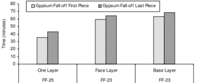
Assemblies with steel C-joists: The fall-off time of the gypsum board layers for assemblies FF-25 (one layer) and FF-23 (two layers) is shown in Figure 5. The first and last pieces of gypsum board fell-off at around 35 and 43 minutes for the assembly protected with one layer of gypsum board while the fall-off of the first and last pieces of the face layer of the assembly protected with double layers of gypsum board was recorded at around 59 and 64 minutes. A significant delay of 24 minutes, compared to the wood joist assemblies with no insulation in the floor cavity discussed above, resulted by adding another layer of gypsum board. The first and last pieces of the base layer fell-off at around 63 and 68 minutes. This shows that the protection time of the frame increased by 28 minutes when adding a second layer of 12.7 Type X gypsum board.
Figure 5 Gypsum board fall-off in steel C-joist assemblies with insulation in cavity
The results of the assemblies studied above for solid wood, wood-I and steel joists showed that the addition of another layer of gypsum board delayed substantially the first piece fall-off time of the fire exposed gypsum board layer by approximately 23 min for assemblies with insulation in the floor cavity and by approximately 5 min for assemblies with no insulation in the floor cavity. This could be due to the trap of the water migration within the gypsum board base layer caused by the presence of insulation.
0 10 20 30 40 50 60 70 80
One Layer Face Layer Base Layer
FF-25 FF-23 FF-23 T ime ( m inut es )
Gypsum Fall-off First Piece Gypsum Fall-off Last Piece
Effect of Resilient Channels Installation and Spacing on Gypsum Board Fall-off Time
Non-insulated assemblies with one layer of gypsum board: Four non-insulated wood joist assemblies, FF-01A; FF-02A; FF-30; and FF-33, were studied to investigate the effect of the resilient channels installation and spacing on the fall-off time of gypsum board layers. The assemblies were protected with only one layer of 12.7 mm thickness Type X gypsum board on the fire-exposed side. Assembly FF-01A was constructed without resilient channels, however, Assemblies FF-02A, FF-30, and FF-33 were constructed with resilient channels spaced at 406 mm o.c., 406 mm o.c., and 203 mm o.c., respectively, between the solid wood joists and gypsum board ceiling finish.
Figure 6 shows the fall-off time of the first and last pieces of gypsum board for the above four assemblies. The fall-off time for the first and last pieces of gypsum board for the assembly without resilient channels, FF-01A, occurred at approximately 24 and 31 minutes, respectively. The first and the last pieces of gypsum board for the assembly with resilient channels, FF-02A, installed at a spacing of 406 mm fell-off at around 42 and 47 minutes. In assembly FF-30 with resilient channels installed at a spacing of 406 mm, the first and last pieces of gypsum board fell-off at approximately 41 and 43 minutes, respectively. The fall-off time of the first and last pieces of gypsum board for the assembly with resilient channels, FF-33, installed at a spacing of 203 mm was around 39 and 42 minutes, respectively. These results show that decreasing the resilient channels spacing from 406 mm to 203 mm does not significantly affect the fall-off of gypsum board.
Figure 6 Gypsum board fall-off in non-insulated wood Figure 7 Gypsum board fall-off in non-insulated joist assemblies with and without resilient channels wood joist with resilient channels
20.00 25.00 30.00 35.00 40.00 45.00 50.00
First Piece Last Piece Gypsum Fall-off T im e ( m in ut e) FF-01A No RC FF-02A RC @ 406 FF-30 RC @ 406 FF-33 RC @ 203 30.00 35.00 40.00 45.00 50.00
First Piece Last Piece Gypsum Fall-off T im e ( m in inute) FF- 34 RC @ 203 FF- 66 RC @ 406
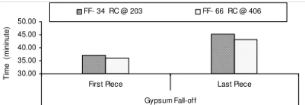
Insulated assemblies with one layer of gypsum board: Two solid wood joist assemblies with
insulation in the floor cavity, FF-34 and FF-66, were studied to investigate the effect of
increasing the resilient channel spacing from 203 to 406 mm, respectively, on the fall-off time of
gypsum board. The assemblies were protected with one layer of Type X gypsum board, 15.9
mm thick, installed on the fire-exposed side. The assemblies were constructed with rock fibre
insulation of 89 mm thick, installed above resilient channels and between wood joists. Figure 7
shows that the first and last pieces of gypsum board fell-off at around 37 and 45 minutes for
assembly FF-34 and 36 and 43 minutes for assembly FF-66. The finding shows that like the
non-insulated assembly mentioned above, decreasing the resilient channels spacing from 406 to
203 mm for insulated assemblies
does not significantly affect the fall-off of gypsum board.Non-insulated assemblies with two layers of gypsum board
Two solid wood joist assemblies FF-28 and FF-31 with two layers of Type X gypsum board were studied to investigate the effect of the resilient channels installation on the gypsum board fall-off time. The assemblies were constructed without insulation in the floor cavity. The resilient channels were spaced at 406 mm o.c. in Assembly FF-28 while Assembly FF-31 was constructed without resilient channels. Figure 8 shows the fall-off time of the gypsum board layers for assemblies FF-28 and FF-31. The first and last pieces of the face layer of gypsum board occurred at approximately 44 and 61 minutes for assembly FF-28 while for assembly FF-31 occurred at 56 and 61 minutes. The first and last pieces of the base layer of gypsum board fall-off for FF-28 occurred at about 67 and 69 minutes while for Assembly FF-31 occurred at around 65 and 67 minutes. The data show that fabrication of the assembly without resilient channels (FF-31) resulted in a delay of the fall-off time of gypsum board especially for the first fall-off of the gypsum board face layer.
Two additional solid wood joist assemblies FF-29 and FF-68 were studied to investigate the effect of the resilient channels spacing on the fall-off of gypsum board layers. The resilient channels were spaced at 406 mm for Assembly FF-29 and at 610 mm for Assembly FF-68. Figure 9 shows that the first and last pieces of face layer of gypsum board for assembly FF-29 were recorded at around 45 and 53 minutes while for FF-68 it was recorded at approximately 48 and 53 minutes. Also, Figure 9 shows the fall-off time of the first and last pieces of the base layer of gypsum board, which occurred at about 59 and 62 minutes for FF-29 and at approximately 52 and 53 minutes for Assembly FF-68. This finding shows a slight acceleration of the fall-off of the face layer of gypsum board for the assembly with resilient channel spacing of 406 mm (FF-29). However, as expected, the gypsum board fall-off for the base layer was faster in the assembly with wider resilient channel spacing.
Based on the results mentioned above for different assemblies protected with two layers of gypsum board, the installation of the resilient channels did not improve the behaviour of the gypsum board regardless of the spacing. The presented data also showed that changing the resilient channel spacing from 406 mm to
203 mm had insignificant effect on the fall-off of gypsum board. In contrast, increasing the spacing from 406 mm to 610 mm had a significant negative effect on the fall-off of gypsum board.
Figure 8 Effect of resilient channels installation Figure 9 Effect of resilient channels installation
20.00 30.00 40.00 50.00 60.00 70.00
First Piece Last Piece First Piece Last Piece
Face Layer Base Layer
Gypsum Fell-off Gypsum Fell-off
T im e ( m in u te ) FF-29 RC @ 406 FF-68 RC @ 610 20.00 30.00 40.00 50.00 60.00 70.00 80.00
First Piece Last Piece First Piece Last Piece Face Layer Base Layer Gypsum Fell-off Gypsum Fell-off
T im e ( m in u te) FF-28 RC @ 406 FF-31 No RC
on the gypsum board fall-off in assemblies with on the gypsum board fall-off in assemblies with layers of gypsum board and no insulation layers of gypsum board and no insulation
Effect of insulation installation in floor cavity on board fall-off time
Assemblies with one layer of gypsum board: Four solid wood joist floor assemblies, 02A, 07, FF-08, and FF-09 with one layer of Type X gypsum board, were studied to determine the effect of the cavity insulation installation and type on the fall-off time of gypsum board. Assembly FF-02A was fabricated without insulation in the floor cavity while Assemblies FF-07; FF-08; and FF-09 were constructed with wet sprayed cellulose fibre, glass fibre, and rock fibre insulation, respectively. The thickness of the glass and rock fibre batts was 90 mm while the average thickness of the cellulose fibre was 93 mm on the underside of the sub-floor and 86 mm on the sides of the joists.
Figure 10 Effect of insulation installation Figure 11 Effect of insulation installation
20.00 25.00 30.00 35.00 40.00 45.00 50.00
First Piece Last Piece
Gypsum Fall-off T ime ( m inutes ) . FF-37 (Non insulated) FF-50 (C1- 91/112) FF-38 (R-178) 20.00 25.00 30.00 35.00 40.00 45.00 50.00
First Piece Last Piece
Gypsum Fall-off T ime ( m inut es ) . FF-02A (Non-insulated) FF-07 (C1-93/86) FF-08 (G) FF-09 (R.)
on the gypsum board fall-off time in assemblies with on the gypsum board fall-off time in assemblies with wood joists and one layer of gypsum board steel C-joists and one layer of gypsum board
Figure 10 shows the time of the fall-off of the first and last pieces of gypsum board protecting the four assemblies. The assemblies insulated with glass and rock fibre batts had an early gypsum board fall-off. The fall-off time of the first and last pieces of gypsum board for FF-08 was at approximately 26 and 31 minutes and at around 26 and 32 minutes for FF-09. A delay is noticed for the assembly insulated with cellulose fibre insulation, the first piece and last pieces of gypsum board for FF-07 fell-off at around 34 and 38 minutes. The first and last pieces of gypsum board fall-off for the non-insulated assembly, FF-02A, occurred at around 42 and 47 minutes. This result shows that the gypsum board fall-off was delayed when using a non-insulated assembly regardless of the type of cavity insulation. This delay is due to the increased heat transfer to the floor cavity in non-insulated assemblies, which reduces the temperature of the gypsum board. On the other hand, the installation of the glass and rock fibre batts at the bottom of the floor cavity (on top of the resilient channels) added thermal resistance and reduced the heat transfer and consequently, increased the rate of rise of the temperature of the gypsum board and that resulted in an early fall-off. This reason also applies to the assembly insulated with cellulose fibre; however, there was a delay of the gypsum fall-off since the insulation was sprayed at the top of the floor cavity.
In addition to the solid wood joist mentioned above, the performance of the steel C-joist assemblies FF-37, FF-38, and FF-50 with one layer of Type X gypsum board is studied to investigate the effect of the cavity insulation installation and type on the fall-off time of the gypsum board. Assembly FF-37 was fabricated without cavity insulation while FF-38 was insulated with rock fibre insulation, 178 mm thick, and Assembly FF-50 was insulated with cellulose fibre insulation sprayed, 91 mm thick at the top of the cavity and 112 mm thick at the sides of the joists. Figure 11 shows the fall-off time for the first and last pieces of gypsum board of the steel joist assemblies. The fall-off time of the first and last pieces of gypsum board for the assembly insulated with rock fibre batts, FF-38, occurred at approximately 27 and 39 minutes while the fall-off time of the first and last pieces of gypsum board for the assembly insulated with cellulose fibre, FF-50, was at about 34 and 45 minutes. The figure also shows the fall-off time of the first and last pieces of the base layer of gypsum board for assembly FF-37, non-insulated assembly, which occurred at about 36 and 39 minutes. Like the results of assemblies with wood joists mentioned above, the comparison of the results shows that the first piece of gypsum board fell-off faster in the assembly insulated with rock fibre than those of non-insulated and with cellulose fibre insulation and the reason for that is the rock fibre insulation was located above the gypsum board which added thermal resistance to the board while in the non-insulated assembly and assembly with cellulose fibre located at the top of the board was facing the cavity with no direct thermal resistance which allowed the heat to be transferred to the cavity and board faced a less severe condition.
Based on the results of assemblies studied above, the installation of either the glass or rock or cellulose fibre insulation in assemblies with one layer of gypsum board had accelerated the fall-off of the gypsum board compared to an assembly with no insulation in floor cavity. However, the cellulose fiber had less severe effect than either the rock or the glass fibre insulation on the gypsum board fall-off.
Assemblies with two layers of gypsum board
Three wood joist assemblies with two layers of Type X gypsum board, FF-03A, FF-04A, and FF-06, were studied to investigate the effect of the floor cavity insulation installation and type on the fall-off time of the gypsum board layers. Assembly FF-03A was fabricated without cavity insulation while Assemblies FF-04A and FF-06 were insulated with rock fibre batts and glass fibre batts, 90 mm, thick.
Figure 12 Effect of cavity insulation installation Figure 13 Effect of cavity insulation installation
20.00 30.00 40.00 50.00 60.00 70.00 80.00 90.00
First Piece Last Piece First Piece Last Piece
Face Layer Base Layer
Gypsum Fall-off Gypsum Fall-off
T im e ( m inute s )
. FF-03A (Non-Insulated) FF-04A (R) FF-06 (G)
20.00 30.00 40.00 50.00 60.00 70.00 80.00
First Piece Last Piece First Piece Last Piece
Face Layer Base Layer
Gypsum Fall- off Gypsum Fall- off
T im e ( m inute) FF-22 (Non-insulated) FF-23 (G)
and type for wood joist assemblies and type for steel C-joist assemblies
Figure 12 shows that the fall-off time of the first piece of the face of gypsum board for the three assemblies FF-03A (no insulation), FF-04A (rock fibre insulation), and FF-06 (glass fibre insulation) occurred at about 50, 48, and 45 minutes, respectively, whereas the fall-off time for the last pieces of the face layer of gypsum board was recorded at approximately 57, 53, and 49 minutes. The fall-off time of the first and last pieces of the base layer of gypsum board for the assemblies is also shown in Figure 12. For assembly FF-03A, it occurred at around 78 and 82 minutes while for assemblies FF-04A and FF-06 it was at approximately 57 and 64 minutes, and at roughly 57 and 63 minutes. The results shows that an early fall-off of the gypsum board layers for the insulated assemblies with either rock or glass fibre compare to the fall-off time of the assembly with no insulation in floor cavity. As mentioned above, the installation of either rock or glass fibre above the gypsum board created an additional thermal resistance
and caused more heat to be retained within the gypsum board and consequently the board fell-off earlier in the insulated assembly compared to the non-insulated assembly.
The effect of the floor cavity insulation installation on the fall-off time for steel C-joist assemblies with two layers of Type X gypsum board was studied. The floor cavity was insulated with glass fibre batts in Assembly FF-24 while Assembly FF-23 was fabricated without cavity insulation. The fall-off time of the gypsum board layers for FF-22 and FF-23 is shown in Figure 13. The first and last pieces of the face layer of gypsum board fell-off at about 66 and 73 minutes for Assembly FF-22 whereas for Assembly FF-23, the fall-off time occurred at approximately 59 and 64 minutes. The figure also shows that the fall-off time of the first and last pieces of the base layer of gypsum board for the non-insulated assembly occurred at 73 and 74 minutes and for the assembly non-insulated with glass fibre batts at 63 and 69 minutes. The result shows that like the assemblies with wood joists mentioned above, for steel C-joist floor assemblies, the addition of insulation decreases the fall-off time.
Based on the results of assemblies with ether one or two layers of gypsum board, the installation
of insulation accelerates the fall-off of the gypsum board.
Effect of framing type on board fall-off time`
Four floor assemblies fabricated with solid wood joists (FF-29), wood-I-joist (FF-15), wood truss
(FF-42), and steel C-joist (FF-23) were studied to investigate the effect of the frame type on the
fall-off time in assemblies with two layers of Type X gypsum, glass fibre insulation and resilient
channels spaced at 406 mm o.c. The assemblies were fabricated with glass fibre batts insulation,
89 mm thick, in the floor cavity above the resilient channels. Figure 14 shows the fall-off time
of the gypsum board for the four assemblies. The fall-off of the first and last pieces of the face
layer of gypsum board occurred at around 45 and 53 minutes for the wood joist assembly, FF-29,
53 and 59 minutes for the wood-I-joist assembly, FF-15, 54 and 59 minutes for the wood truss
assembly, FF-42, and at roughly 59 and 64 for the steel joist assembly, FF-23. The first and last
piece of the base layer as shown in Figure 14 fell-off at approximately 59 and 62 minutes for
FF-29, 57 and 66 minutes for FF-15, 61 and 65 minutes for FF-42, and at about 63 and 69 minutes
for FF-23. The results for the face layer show that wood-I-joist assemblies behave similarly to
wood truss assemblies while wood joist assemblies have an early fall-off time. However, for the
base layer, results show that the fall-off time is more or less the same (between 57 to 63 min).
These results show that the effect of the frame type on the gypsum board fall-off is insignificant.
Figure 14 Effect of the frame type for assemblies insulated Figure 15 Effect of the frame type for assemblies
0.00 10.00 20.00 30.00 40.00 50.00 60.00 70.00 80.00
First Piece Last Piece First Piece Last Piece
Face Layer Base Layer
Gypsum Fall-off Gypsum Fall-off
T im e ( m in u te s ) . FF-29 WJ FF-15 WIJ FF-42 WT FF-23 SJ 0.00 10.00 20.00 30.00 40.00 50.00 60.00 70.00
First Piece Last Piece First Piece Last Piece
Face Layer Base Layer
Gypsum Fall-off Gypsum Fall-off
T im e ( m in u te s ) . FF-67 WJ FF-20 WIJ FF-79 WT FF-52 SJ
with glass fibre batts, two layers of gypsum board insulated with glass fibre, two layers of gypsum and resilient channels at 406 mm board and resilient channels at 610 mm
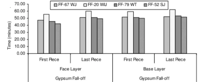
Four assemblies fabricated with wood joist (FF-67), wood-I-joist (FF-20), wood truss (FF-79), and steel C-joist (FF-52) were studied to investigate the effect of the frame type on the fall-off time for assemblies with two layers of Type X gypsum board, glass fibre insulation and resilient channels spaced at 610 mm
o.c. Figure 15 shows the fall-off time of the gypsum board for the four assemblies. The fall-off time of the first and last pieces of the face layer of gypsum board occurred at around 47 and 51 minutes for the wood joist assembly, FF-67, 56 and 60 minutes for the wood-I-joist assembly, FF-20, 45 and 51 minutes for the wood truss assembly FF-79 and at roughly 42 and 50 minutes for the steel joist assembly FF-52. The first and last piece of the base layer occurred at approximately 52 and 52 minutes for FF-67, 59 and 62 minutes for FF-20, 51 and 54 minutes for FF-79 and at about 50 and 52 minutes for FF-52. The results show that unlike the assemblies with resilient channels spaced at 406 mm o.c., the assemblies with different types of frames where resilient channels spaced at 610 mm o.c., the assembly with wood-I-joists has the longest fall-off time of the gypsum board, while the steel joist assembly have the shortest fall-off time.
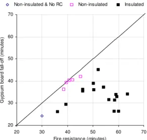
Fire Resistance vs Gypsum Board Fall-off
ypsum board can provide up to 90% of the assemblies’ protection2, therefore, its fire resistance depends
Figure 16 Fire resistance vs Gypsum Board-fall in Assemblies with One Layer of Gypsum Board imilar behaviour was observed for assemblies protected with two layers of gypsum board. Figure 17 G
on how long gypsum panels remain in place and protect the floor frame. Figure 16 shows a plot for the fire resistance and fall-off time of the first piece of gypsum board for the assemblies protected with a single layer of Type X gypsum board with and without insulation in the floor cavity. The results show that the fire resistance is fairly close to the fall-off time of the first piece of gypsum board for those assemblies with no insulation. However, in assemblies with insulation, the scatter was large. Therefore, for assemblies with one layer of gypsum board and no insulation in floor cavity, the fire resistance correlates well with the fall-off time of the gypsum board.
20 30 40 50 60 70 20 30 40 50 60 70
Fire resistance (minutes)
G y p s u m bo ar d fa ll-o ff ( m in ute s )
Non-insulated & No RC Non-insulated Insulated
S
shows that the assemblies fabricated without cavity insulation had fire resistance close to its fall-off time of the first piece of the base layer of gypsum, therefore, there is a good correlation between the fire resistance and the gypsum board fall-off for non-insulated assemblies with two layers of Type X gypsum board. However, in insulated assemblies, the correlations for both assemblies with one and two layers of gypsum board are weak. Further analysis is being conducted at the National Research Council to determine the reasons.
Figure 17 Fire resistance vs Gypsum Board-fall in Assemblies with Two Layers of Gypsum Board
CONCLUSIONS
This paper presents the experimental results of eighty fire resistance tests conducted at the National Research Council of Canada and analysed jointly with Carleton University to investigate the impact of various parameters on the gypsum board fall-off time in floor assemblies with wood, wood-I and steel C-joists as well as wood trusses protected with either one or two layers of Type X gypsum board and with and without insulation in floor cavity. Based on the analysis, the following key findings can be drawn: 40 50 60 70 80 90 100 110 40 50 60 70 80 90 100 110
Fire resistance (minutes)
G y ps u m bo ar d f al l-of f ( m in ut es ) Non-insulated & RC @ 610 St/Con Non-insulated Insulated
1. Adding a second layer of gypsum board delayed the fall-off time for the fire exposed gypsum board layer, however, in an assembly with two layers of gypsum board, the base layer did not remain attached as long as the face layer.
2. Increasing resilient channels spacing from 203 mm to 406 mm had an insignificant effect on the fall-off of gypsum board; however, increasing the spacing from 406 mm to 610 mm had a significant negative effect on the fall-off time of the gypsum board.
3. In assemblies with the same number of gypsum board, adding insulation in the floor cavity decreases the gypsum board fall-off time.
4. The effect of the frame type on the gypsum board fall-off is insignificant.
5. In assemblies with either one layer or two layers of gypsum board and no insulation in the floor cavity, the fire resistance correlates well with the fall off time of the gypsum board.
REFERENCES
1. Sultan, M.A., Seguin, Y.P., Leroux, “Results of Fire Resistance Tests on Full-Scale Floor Assemblies”, Internal Report No. 764, Institute for Research in Construction, National Research Council of Canada, Ottawa, ON, 1998.
2. Sultan, M.A, Latour, J.C., Leroux, P., Monette, R.C., Seguin, Y.P. and Henrie, J. “Results of Fire Resistance Tests on Full-scale Floor Assemblies – Phase II”, Research Report 184, Institute for Research in Construction, National Research Council Canada, Ottawa, Ontario, 2005.
3. Elewini, E. “Performance of Gypsum Board Exposed to Fire” M.Sc. Thesis, Department of Civil and Environmental Engineering, Carleton University, Ottawa, Canada, 2006.
4. CAN/CSA-A82.31-M91, Gypsum Board Application, Canadian Standards Association, Rexdale, ON, 1991.
5. CSA A101-M83, Thermal Insulation, Canadian Standards Association, Rexdale, Ontario, 1983. 6. CAN/ULC-S702-M97, Standard for Mineral Fibre Thermal Insulation for Buildings, Underwriters’
Laboratories of Canada, Scarborough, Ontario, 1997.
7. CAN/CGSB 51.60-M90, Cellulose Fibre Loose Fill Thermal Insulation, Canadian Standards Board, Ottawa, Ontario, 1990.
8. CAN/CSA-82.27-M91, Gypsum Board, Canadian Standards Association, Etobicoke, Ontario, Canada, 1991.
9. ASTM C36-97, Standard Specification for Gypsum Wallboard, American Society for Testing and Materials, West Conshohocken, PA, June 1997.
10. CAN/ULC-S101-M89, Standard Methods of Fire Endurance Tests of Building Construction and Materials. Underwriters' Laboratories of Canada, Scarborough, ON, 1989.
11. ASTM E119-88, Standard Test Method for Fire Tests of Building Construction and Materials, ASTM, West Conshohocken, PA, 1988.
Table-1: Parameters and Results for test assemblies First Piece Last Piece First Piece Last Piece
FF-01A WJ 235 406 1 12.7 X 1 Ply 15.9 *** *** *** *** 3830 30 Flame --- --- 24.22 31.20
FF-02A WJ 235 406 1 12.7 X 1 Ply 15.9 *** *** *** 406 3830 45 Flame --- --- 42.07 47.20
FF-03A WJ 235 406 2 12.7 X 1 Ply 15.9 *** *** *** 406 3830 80 Flame 49.42 57.30 77.43 82.20
FF-04A WJ 235 406 2 12.7 X 1 Ply 15.9 R 90 B 406 3830 72 Flame 48.19 53.15 56.50 63.43
FF-06 WJ 235 406 2 12.7 X 1 Ply 15.9 G 90 B 406 3830 67 Flame 44.43 48.50 57.30 62.45
FF-07 WJ 235 406 1 12.7 X 1 Ply 15.9 C1 93a/86b T 406 3830 59 Flame --- --- 34.00 38.22
FF-08 WJ 235 406 1 12.7 X 1 Ply 15.9 G 90 B 406 3830 36 Flame --- --- 26.14 31.00
FF-09 WJ 235 406 1 12.7 X 1 Ply 15.9 R 90 B 406 3830 60 Flame --- --- 26.35 32.11
FF-10 WIJ2 240 406 2 12.7 X 1 Ply 15.9 *** *** *** 406 3926 69 Struct 47.53 57.59 68.36 70.45
FF-11 WIJ5 240 406 2 12.7 X 1 Ply 15.9 *** *** *** 406 3830 74 Struct 49.47 65.15 73.46 76.45
FF-12 WIJ4 240 406 2 12.7 X 1 Ply 15.9 *** *** *** 406 4405 80 Flame 54.24 62.43 78.55 82.25 FF-13 WIJ2 240 406 2 12.7 X 1 Ply 15.9 *** *** *** 406 3926 72 Struct 56.06 70.00 69.18 74.20
FF-14 WIJ2 240 406 1 12.7 X 1 Ply 15.9 *** *** *** 406 4597 42 Struct --- --- 40.53 44.00
FF-15 WIJ2 240 406 2 12.7 X 1 Ply 15.9 G 90 B 406 3950 64 Struct 53.16 59.33 56.50 66.00
FF-16 WIJ2 240 406 1 12.7 X 1 Ply 15.9 R 90 B 406 4644 46 Struct --- --- 36.36 43.07
NRC-02 WIJ2 240 406 2 12.7 X 1 Ply 15.9 R 90 B 406 3950 77 Struct 59.28 66.31 67.04 75.18
FF-17 WIJ2 240 610 2 12.7 X 1 Ply 19 G 90 B 406 2969 75 Struct 59.35 69.24 69.04 74.50
FF-18 WIJ2 240 610 2 12.7 X 1 Ply 19 G 90 B 406 2490 74 Flame 60.00 65.16 68.16 70.20
FF-19 WIJ2 240 406 1 12.7 X 1 Ply 15.9 C1 88a/102b T 406 4046 52 Struct --- --- 45.10 46.53
FF-20 WIJ2 240 610 2 12.7 X 1 Ply 19 G 90 B 610 3112 65 Struct 55.41 60.00 59.38 62.01
FF-22 SJ 203 406 2 12.7 X 1 Ply 15.9 *** *** *** 406 2945 74.3 Struct 66.26 73.19 73.09 74.00 FF-23 SJ 203 406 2 12.7 X 1 Ply 15.9 G 90 B 406 2945 68 Struct 59.23 64.06 63.26 68.40 FF-24 SJ 203 610 2 12.7 X 1 Ply 15.9 G 90 B 406 1796 69 Struct 59.48 62.06 65.04 67.23 FF-25 SJ 203 406 1 12.7 X 1 Ply 15.9 R 90 B 406 2945 46 Struct --- --- 35.50 43.17 FF-26 St\Con *** *** 2 12.7 X 1 *** *** *** *** *** 406 4812 105 Struct 52.52 72.14 74.06 81.48 FF-27 SJ 203 406 2 12.7 X 1 Ply/Con 15.9/38 G 90 B 406 1915 60 Struct 49.26 55.24 53.22 58.05 FF-28 WJ 235 406 2 12.7 X 1 Ply 15.9 *** *** *** 406 5075 69 Struct 43.49 60.58 67.09 68.55 FF-29 WJ 235 406 2 12.7 X 1 Ply 15.9 G 90 B 406 5075 69 Struct 45.13 52.54 59.01 62.12 FF- 30 WJ 235 406 1 12.7 X 1 Ply 15.9 *** *** *** 406 5123 40,49 Struct --- --- 40.43 43.00 FF-31 WJ 235 406 2 12.7 X 1 Ply 15.9 *** *** *** *** 5027 67.1 Struct 56.06 61.1 65.32 67.12 FF-32 WJ 184 406 2 12.7 X 1 Ply 15.9 G 89 B 406 3304 67.15 Struct 53.08 57.08 60.10 62.30 Thick-ness (mm) Layer Number Thick-ness (mm) Type Type Layer Number Cavity Insulation Base Layer Load (N/m2) Fire Resist-ance (min.s) Mode of failure
Gypsum Board Fall-Off (min.sec) Face Layer Thick-ness (mm) Sub Floor Type Locat-ion Spacing (mm) Assembly Number
Joist Ceiling Finish
Type Depth (mm)
Spacing (mm)
First Piece Last Piece First Piece Last Piece FF- 33 WJ 235 406 1 12.7 X 1 Ply 15.9 *** *** *** 203 5123 39,55 Struct --- --- 39.35 42.00 FF- 34 WJ 235 406 1 15.9 X 1 Ply 15.9 R 89 B 203 5075 54,11 Struct --- --- 37.19 45.26 FF-35 WJ 235 406 2 12.7 X ---- Ply/GC 15.9/25.4 G 89 B 406 4644 68.27 Struct 53.14 57.50 60.44 64.00 FF- 36 WJ 235 406 1 15.9 X 2 Ply 15.9 R 178 B 406 4980 58,49 Struct --- --- 31.36 41.34 FF- 37 SJ 203 406 1 15.9 X 2 Ply 15.9 *** *** *** 406 3366 38,49 Struct --- --- 36.30 39.13 FF- 38 SJ 203 406 1 15.9 X 2 Ply 15.9 R 178 B 406 3318 53,38 Struct --- --- 26.41 38.43 FF-40 SJ 203 406 2 12.7 X ---- St/Con 51 *** *** *** 406 2351 75 Struct 60.39 76.55 72.35 79.12 FF-41 WT1 305 406 2 12.7 X 1 Ply 15.9 *** *** *** 406 5602 69.01 Struct 57.43 66.46 68.12 71.00 FF-42 WT1 305 406 2 12.7 X 1 Ply 15.9 G 89 B 406 5602 65.41 Struct 53.49 59.35 60.55 65.32 FF-43 SJ 203 406 2 12.7 X ---- St/Con 51 G 89 B 406 2341 68.25 Struct 54.28 59.41 60.10 66.11 FF-44 SJ 203 406 2 12.7 X ---- St/Con 51 G 89 B 610 2341 61 Struct 52.32 54.35 53.30 59.15
FF- 45 WIJ1 241 406 1 15.9 X 1 OSB 15.9 R 178 B 406 5315 39,31 Struct --- --- 29.58 37.58
FF-46 WT2 305 406 2 12.7 X 1 Ply 15.9 G 89 B 406 4213 67.36 Struct 55.19 59.45 61.41 67.40 FF-47 WT1 305 406 2 12.7 X ---- Ply/Con 15.9/38 G 89 B 406 5123 72 Struct 52.10 57.02 60.02 63.12 FF-48 WT1 305 610 2 12.7 X 1 Ply 15.9 G 89 B 406 3783 68.18 Struct 53.50 59.02 62.23 65.54 FF- 49 WJ 235 406 1 15.9 X 2 Ply 15.9 C1 55a /79b T 406 4980 54,13 Struct --- --- 37.31 44.18 FF- 50 SJ 203 406 1 15.9 X 2 Ply 15.9 C1 91a /112b T 406 3285 63,47 Struct --- --- 34.17 45.00 FF-51 SJ 203 406 2 12.7 X 1 Ply 15.9 *** *** *** *** 3342 65.55 Flame 51.16 61.29 66.39 68.45 FF-52 SJ 203 610 2 12.7 X 1 Ply 19 G 89 B 610 2097 52.3 Struct 42.17 49.50 50.14 51.41 FF-53 SJ 203 406 2 12.7 X ---- St/Con 51 R 89 B 406 2341 70 Struct 51.06 57.17 57.46 64.53 FF-54 SJ 203 610 2 12.7 X ---- St/Con 51 *** *** *** *** 1130 66 Struct 37.38 56.18 60.37 66.04
FF-55 WIJ2 241 610 2 12.7 X 1 OSB 19 G 89 B 406 3447 60.59 Struct 48.36 57.28 56.08 60.00
FF-56 WT3 406 406 2 12.7 X 1 Ply 15.9 *** *** *** 406 5650 65.05 Struct 54.35 62.08 61.51 64.24
FF- 57 WIJ6 241 610 1 15.9 X 2 OSB 15.9 R 89 B 305 4118 50,17 Struct --- --- 39.08 43.41
FF-58 WT4 330 406 2 12.7 X 1 Ply 15.9 G 89 B 406 6847 63.37 Struct 48.50 56.19 54.42 63.11 FF-59 WT1 305 610 2 12.7 X 1 Ply 19 G 89 B 610 3783 54.35 Struct 40.25 49.02 48.01 52.31 FF-60 WT1 305 406 2 12.7 X 1 Ply 15.9 *** *** *** *** 5602 61.03 Struct 43.15 58.45 59.07 60.55 FF-61 WIJ2 241 406 2 12.7 X ---- Ply/Con 15.9/38 G 89 B 406 4596 66.58 Struct 49.39 56.24 57.14 61.46 FF-62 SJ 203 610 2 12.7 X 1 Ply 19 *** *** *** *** 2123 54.59 Struct 46.15 55.31 54.07 56.00 FF-63 WT5 286 406 2 12.7 X 1 Ply 15.9 G 89 B 406 3543 64.04 Struct 51.28 57.23 57.07 62.34 FF-64 WJ 235 610 2 12.7 X 1 Ply 19 *** *** *** 610 3256 58.55 Struct 47.08 55.23 54.55 61.30 Face Layer Mode of failure
Gypsum Board Fall-Off (min.sec) Layer Number Cavity Insulation Base Layer Fire Resist-ance (min.s) Layer Number Load (N/m2 ) Type Thick-ness (mm) Locat-ion Spacing (mm) Thick-ness (mm) Type Assembly Number
Joist Ceiling Finish Sub Floor
Type Thickne ss (mm) Type Depth (mm) Spacing (mm)
First Piece Last Piece Fir Pie FF-65 SJ 203 610 2 12.7 X 1 Ply 19 C3 94a/100 st ce Last Piece b T 610 2092 68.55 Struct 48.45 52.08 52.39 FF- 66 WJ 235 406 1 15.9 X 1 Ply 15.9 R 89 B 406 5219 50,24 Struct --- --- 36.18 FF-67 WJ 235 610 2 12.7 X 1 Ply 19 G 89 B 610 3256 57.05 Struct 47.29 51.09 51.46 FF-68 WJ 235 406 2 12.7 X 1 Ply 15.9 G 89 B 610 5027 57.27 Flame 48.02 53.10 51.58 FF-69 WJ 235 610 2 12.7 X 1 Ply 19 R 89 B 610 3256 63.33 Struct 49.29 51.51 52.38 FF-70 WJ 235 406 2 12.7 X 1 Ply 15.9 C2 235 --- 610 4980 87.2 Struct 48.02 52.03 52.03 FF-71 WT1 305 610 2 12.7 X 1 Ply 19 *** *** *** *** 3783 56.16 Struct 44.41 51.19 54.28 FF-72 WT1 305 610 2 12.7 X 1 Ply 19 C1 89 T 610 3687 77.12 Struct 49.04 54.09 54.18 FF-73 WJ 235 610 2 12.7 X 2 Ply 15.9 G 89 B 610 3783 58.43 Struct 48.19 51.49 51.49 FF- 74 SJ 203 610 1 15.9 X ---- St/Con 51 C1 38a/89b T 406 3687 56,20 Struct --- --- 31.57 FF-75 WT1 305 610 2 12.7 X ---- Ply/Con 19/38 G 89 B 610 3208 60.55 Struct 44.12 50.03 50.28
FF- 76 WIJ3 241 406 1 15.9 X 2 Ply 15.9 C2 241 --- 305 5410 80,19 Struct --- --- 38.58
FF-77 WIJ2 241 406 2 12.7 X 1 Ply 15.9 *** *** *** *** 5506 64.31 Struct 52.21 62.02 63.42
FF- 78 WIJ3 241 406 1 15.9 X 2 Ply 15.9 R 267 B 305 5458 59,38 Struct --- --- 33.00
FF-79 WT1 305 610 2 12.7 X 1 Ply 19 G 89 B 610 3783 54.35 Struct 45.31 51.30 51.27
FF-80 WT1 305 610 2 12.7 X 1 Ply 19 R 89 B 610 3735 59.34 Struct 45.10 50.24 50.24
FF-81 WIJ3 241 406 2 15.9 X 2 Ply 15.9 R 267 B 305 5363 90.19 Struct 56.41 62.48 65.41
FF-82 WT1 305 406 2 15.9 X 2 Ply 15.9 C2 305 --- 406 5793 99.14 Struct 50.50 63.13 61.33 WIJ 54.26 43.18 52.39 53.24 56.25 55.41 56.13 57.07 53.20 40.15 53.07 48.32 63.50 42.16 53.57 53.10 76.03 68.40
1 -44 mm wide x 38 mm deep WT1- 89 mm wide
OSB-Oriented strandboard
WIJ2 -38 mm wide and 38 mm deep WT2-64 mm wide B-Bottom
WIJ3 -58 mm wide and 38 mm deep WT3- truss oriented vertically
T-Top WIJ4 -64 mm wide and and 38 mm deep WT4- Finger Jointed wood truss 64 mm wide Struct-Structure WIJ5 -38 mm wide and 64 mm deep WT5- Metat web truss 63 mm wide
WIJ6 -63 mm wide and and 38 mm deep WJ-Wood joist C1- Cellulose Fibre Insulation, Wet Sprayed WIJ-Wood-I-joist C2- Cellulose Fibre Insulation, Dry Blown WT-Wood truss C3- Cellulose Fibre Insulation, Wet Sprayed with Adhesive SJ-Steel joist G-Glass fibre batts insulation Ply-Plywood R-Rock fibre batts insulation St/Con-Steel/Concrete a Cellulose Insulation Thickness on under sub-floor Ply/Con-Plywood/Concrete b Cellulose insulation Thickness on joist sides Ply/GC-Plywood/Gypsum-Concrete
Ba Locat-ion Spacing (mm) Face Layer Fire Resist-ance (min.s) Mode of failure
Gypsum Board Fal (min.sec) Type Depth (mm) Spacing (mm) Layer Number Layer Number Type Thick-ness (mm) Type Thick-ness (mm) Assembly Number
Joist Ceiling Finish Sub Floor Cavity Insulation
Load (N/m2) Thick-ness (mm) Type se Layer l-Off