Publisher’s version / Version de l'éditeur:
Langmuir, 25, 5, pp. 3173-3177, 2009-01-26
READ THESE TERMS AND CONDITIONS CAREFULLY BEFORE USING THIS WEBSITE. https://nrc-publications.canada.ca/eng/copyright
Vous avez des questions? Nous pouvons vous aider. Pour communiquer directement avec un auteur, consultez la première page de la revue dans laquelle son article a été publié afin de trouver ses coordonnées. Si vous n’arrivez pas à les repérer, communiquez avec nous à [email protected].
Questions? Contact the NRC Publications Archive team at
[email protected]. If you wish to email the authors directly, please see the first page of the publication for their contact information.
NRC Publications Archive
Archives des publications du CNRC
This publication could be one of several versions: author’s original, accepted manuscript or the publisher’s version. / La version de cette publication peut être l’une des suivantes : la version prépublication de l’auteur, la version acceptée du manuscrit ou la version de l’éditeur.
For the publisher’s version, please access the DOI link below./ Pour consulter la version de l’éditeur, utilisez le lien DOI ci-dessous.
https://doi.org/10.1021/la803521t
Access and use of this website and the material on it are subject to the Terms and Conditions set forth at
A study of simultaneous patterning and alignment of semiconductor
nanorods via polymerization-induced phase separation
Greener, Jesse; Van Der Loop, Tibert Hendrik; Paquet, Chantal; Scholes,
Gregory; Kumacheva, Eugenia
https://publications-cnrc.canada.ca/fra/droits
L’accès à ce site Web et l’utilisation de son contenu sont assujettis aux conditions présentées dans le site LISEZ CES CONDITIONS ATTENTIVEMENT AVANT D’UTILISER CE SITE WEB.
NRC Publications Record / Notice d'Archives des publications de CNRC:
https://nrc-publications.canada.ca/eng/view/object/?id=065d63e6-6eb5-4a87-a611-c7f89e8701be https://publications-cnrc.canada.ca/fra/voir/objet/?id=065d63e6-6eb5-4a87-a611-c7f89e8701beA Study of Simultaneous Patterning and Alignment of Semiconductor
Nanorods via Polymerization-Induced Phase Separation
Jesse Greener,
†Tibert Hendrik van der Loop,
†,§Chantal Paquet,
‡Gregory Scholes,
†and
Eugenia Kumacheva*
,†Department of Chemistry, UniVersity of Toronto, 80 Saint George Street, Toronto, ON, M5S 3H6 Canada, and Steacie Institute for Molecular Sciences, National Research Council of Canada, 100 Sussex DriVe,
Ottawa, ON, K1A 0R6 Canada
ReceiVed October 22, 2008. ReVised Manuscript ReceiVed December 3, 2008
We report simultaneous patterning and alignment of semiconductor nanorods (NRs) in nanorod-polymer films by using photolithographic polymerization-induced phase separation (PIPS). Exposure of the nanoparticle-monomer mixture to UV irradiation through a mask resulted in the site-specific photoinitiated polymerization of the monomer, which was followed with flow of the NRs from the areas rich in polymer to the areas rich in monomer. The orientation of NRs in the direction of flow was trapped in the polymerized films and characterized in polarization absorption experiments.
Introduction
Alignment of semiconductor and metal nanorods (NRs) allows one to exploit the collective optical and electronic size- and shape-dependent properties of individual nanoparticles. Moreover, the micrometer scale patterning of aligned NRs can lead to interesting properties of the NR arrays, which arise from bridging the nano- and micrometer size regimes. Polarization-dependent absorption properties of aligned NRs in patterned arrays have potential applications in displays,1cryptography, and cell tagging.2
Current methods used for the alignment of anisotropic nanoparticles include heating and stretching of the composite NR-polymer films,3electric field-assisted orientation of
semi-conductor NRs,4,5end-to-end NR self-assembly,6and assembly of NRs on templates such as carbon nanotubes and DNA moolecules.7,8 These methods either produce small-size NR arrays, require multistep procedures, or have not been combined with patterning. On the other hand, laser writing selectively suppresses anisotropic properties of an initially ordered array of nanorods.9
In the present work, we report a preliminary experimental study of the simultaneous alignment and patterning of semi-conductor NRs in polymer films by using polymerization-induced phase separation (PIPS). The method exploits the miscibility of the system (e.g., a monomer and a liquid crystal) prior to
polymerization and phase segregation of the system (e.g., a polymer and a liquid crystal component) during polymerization. PIPS is a robust method that is extensively used for producing polymer-dispersed liquid crystal films and composite thermo-plastics.10-13Recently, PIPS was successfully exploited for the
photolithographic patterning of semiconductor quantum dots in polymer films.14Exposure of the nanoparticle-monomer mixture
to UV irradiation through a mask resulted in the localized photoinitiated polymerization of the monomer, which was followed with flow of nanocrystals from the areas rich in polymer to the areas rich in monomer, due to the favored interactions of nanoparticles with the monomer phase.
Here, we hypothesized that the NRs flowing from the regions exposed to UV light to the light-protected regions are oriented in the direction of flow and upon complete polymerization of the monomer become trapped in that orientation. The preferential orientation of NRs was characterized in polarization absorption experiments. Since the alignment did not rely on the chemical nature of NRs, we expect that the results of this work can be applied to other types of NRs with comparable aspect ratios to produce large area patterned films comprising aligned NRs.
Experimental Section
Materials. The monomer 2-ethylhexyl methacrylate (EHMA, 99%), the photoinitiator 1-hydroxycyclohexyl phenyl ketone (HPCK), cadmium oxide (99.99%), zinc oxide powder (99.9%), sulfur powder (99.98%), selenium powder (100 mesh, 99.999%), tributylphosphine (TBP, 97%), trioctylphosphine (TOP, 97%), 1-octadecene (ODE, 90%), oleic acid (OA, 90%), trioctylphosphine oxide (TOPO, 90%), octadecylamine (ODA, 90%), and trichloro(1H,1H,2H,2H-perfluo-rooctyl)silane, (97%) were purchased from Aldrich Canada. Oc-tadecyl phosphonic acid (ODPA) was purchased at PCI Synthesis. All chemicals were used without further purification. The surfactants TBP, TOP, and TOPO were used in the synthesis of CdSe cores, and ODA, ODE, and OA were used in the synthesis of the ZnS shells.
†University of Toronto.
‡Steacie Institute for Molecular Sciences.
§Current address: Universiteit van Amsterdam, Roeterseiland Complex, Nieuwe achtergracht, 166 1018WV, Amsterdam.
(1) Dirix, Y.; Bastiaansen, C.; Caseri, W.; Smith, P. AdV. Mater. 1999, 11, 223.
(2) Wang, Y.; Tang, Z.; Correa-Duarte, M. A.; Liz-Marza´n, L. M.; Kotov, N. A. J. Am. Chem. Soc. 2003, 125, 2830.
(3) Pe´rez-Juste, J.; Rodrı´guez-Gonza´lez, B.; Mulvaney, P.; Liz-Marza´n, L. M.
AdV. Funct. Mater. 2005, 15, 1065.
(4) Ryan, K. M.; Mastroianni, A.; Stancil, K. A.; Liu, H.; Alivisatos, A. P.
Nano Lett. 2006, 6, 1479.
(5) Gupta, S.; Zhang, Q.; Emrick, T.; Russell, T. P. Nano Lett. 2006, 6, 2066.
(6) (a) Nie, Z.; Fava, D.; Kumacheva, E.; Zou, S.; Walker, G. C.; Rubinstein, M. Nat. Mater. 2007, 6, 609. (b) Nie, Z.; Fava, D.; Winnik, M. A.; Rubinstein, M.; Kumacheva, E. J. Am. Chem. Soc. 2008, 130, 3683.
(7) Dong, L.; Hollis, T.; Connolly, B. A.; Wright, N. G.; Horrocks, B. R.; Houlton, A. AdV. Matter. 2007, 19, 1748.
(8) Jua´rez, B. H.; Klinke, C.; Kornowski, A.; Weller, H. Nano Lett. 2007, 7, 3564.
(9) Wilson, O.; Wilson, G. J.; Mulvaney, P. AdV. Mater. 2002, 14, 1000.
(10) Moschiar, S. M.; Riccardi, C. C.; Williams, R. J. J.; Verchere, D.; Sautereau, H.; Pascault, J. P. J. Appl. Polym. Sci. 1991, 42, 717.
(11) Riccardi, C. C.; Borrajo, J.; Williams, R. J. J. Polymer 1994, 35, 5541.
(12) Nephew, J. B.; Nihei, T. C.; Carter, S. A. Phys. ReV. Lett. 1998, 80, 3276.
(13) Vaia, R. A.; Tomlin, D. W.; Schulte, M. D.; Bunning, T. J. Polymer 2001,
42, 1055.
(14) Paquet, C.; Kumacheva, E. AdV. Funct. Mater. 2007, 17, 3105–3110.
10.1021/la803521t CCC: $40.75 2009 American Chemical Society Published on Web 01/26/2009
Methods. Synthesis of Core-Shell CdSe/ZnS NRs and Their
Patterning.Synthesis of CdSe NRs was accomplished using the protocol described elsewhere.15Following the synthesis of cores,
the ZnS shells were synthesized.16,17For CdSe nanocrystals, their
wurtzite structure results in a broken symmetry along the c-axis, which is the direction of growth and is also the polar axis.18The
growth of the ZnS shell did not significantly alter the aspect ratio of the NRs.17We note that the utilization of CdSe/ZnS NRs was
not critical for their alignment: very similar results were obtained for CdSe nanorods. The use of core-shell CdSe/ZnS nanorods was motivated by their strong photoluminescence in the polymer matrix, in contrast with quenched luminescence of CdSe. The NRs were mixed with 2-ethylhexyl methacrylate comprising 1 wt % photo-initiator, 1-hydroxycyclohexyl phenyl ketone. The mixture of a monomer, nanorods (1-4.5 vol %), and a photoinitiator was introduced in a 100µm thick cell with UV-transparent quartz glass windows. The thickness of the cell and the corresponding thickness of the composite film were optimized to favor PIPS and suppress Rayleigh-Be´nard convection resulting from temperature gradients.14
A shadow mask with a periodic pattern of opaque and transparent regions was placed on the top of the window. The shielded 900µm wide regions of the mask were separated by the 100 µm wide transparent lines. Printing resolution of the masks was 2400 dpi, corresponding to a nominal resolution of 11µm.
Characterization of NRs and Patterned Films. Transmission electron microscope (TEM) images were acquired with a Hitachi HD-2000 scanning transmission electron microscope. Samples for TEM imaging were prepared by depositing a droplet of nanorod solution on a 400 mesh carbon-coated copper grid (Electron Microscopy Sciences). The concentration of the NRs in toluene was chosen such that after evaporation no more than a monolayer was left on the surface. Transmission and photoluminescence images of the patterned hybrid films were acquired with a Roper Scientific photometric CCD mounted on an Olympus EX51 microscope with a 4× magnifying lens. Fluorescence imaging was accomplished with an EXFO X-Cite 120PC XL light source system with a 535 nm/50 excitation filter and a 610 nm/75 fluorescence filter.
Polarization-dependent measurements of absorption and transmis-sion of the hybrid films were conducted using a Varian Cary 5000 UV-vis-near-IR spectrophotometer with polarizing and depolarizing UV-vis optics. All experiments were repeated five times. (Prior to these measurements, with the use of a Harrick crystalline quartz depolarizer, we ensured that the excitation beam exhibited even intensity throughout all linear polarization angles.) A manually operated Bruker polaroid sheet polarizer (positioning accuracy (3.5°) was placed in front of the depolarized excitation beam. To account for the contribution of the polymer in the optical properties of the hybrid film, we examined the NR-depleted regions. The birefringence of these regions for the PIPS film mounted on a glass slide resulted in a 30°polarization of light. In order to prevent artifacts in the detector output, which could arise from the differential detector sensitivity and interference phenomena in its detector-side optics, a second depolarizer, identical to the first, was placed in the beam path after the polymer film. Transmission measurements were conducted for the NR-rich and NR-depleted regions of the film at various polarization angles by using a 0.3 × 10 mm mask. Absorption spectra of the NRs in the films were obtained by relating the transmission spectra of the rich regions to those of the NR-depleted regions via the Beer-Lambert law at a particular polarization angle. The generalized absorption equation at a given polarization angleθ is given by
Aθ) -log
(
Tθ NR-rich
⁄ TθNR-depleted
)
(1) where TθNR-richand TθNR-depletedrepresent transmission spectra of theNR-rich or NR-depleted regions of the film, respectively.
Results and Discussion
Figure 1 schematically shows the approach to the alignment of semiconductor NRs in polymer films. A layer of the mixture of EHMA, CdSe/ZnS NRs, and photoinitiator is exposed through a mask to UV irradiation (Figure 1 (top), t ) 0), which passes through the light-transparent regions of the mask and initiates polymerization of the EHMA in those regions. Since mixing of NRs with the monomer EHMA is favored in comparison with the polymer, NRs diffuse away from the advancing polymer fronts to the UV-shielded regions (Figure 1, t > 0). When polymerization occurs in the light-protected regions (resulting from of a combination of thermal initiation and lateral diffusion of polymerizing molecules), the entire film becomes solidified. We hypothesized that the NRs orient in the direction of flow, so that their long axes are colinear to the diffusion path, and that this alignment can be trapped in the solidified film.
Figure 2A shows the TEM images of the core-shell CdSe/ ZnS NRs used in the present work. The NRs had a mean length and width of 23.7 and 3.8 nm, respectively, so that the aspect ratio was 6.2. The optical properties of the core-shell CdSe/ZnS NRs (as well as CdSe NRs) are presented in Figure 2B. A strong primary absorption peak is centered at 608 nm; a shoulder on a rising background, corresponding to a secondary transition state, is located near 520 nm. The core-shell NRs have dramatically stronger photoluminescence than CdSe rods, which indicated that a ZnS shell had formed around the CdSe core.17 These properties are consistent with those reported previously for the NRs synthesized under similar conditions.15-17In the next step, we ensured that absorbance and emission properties of the core-shell NRs did not change when they were mixed with the 2-ethylhexyl methacrylate monomer or the corresponding polymer.
We first examined the evolution of the PIPS-induced patterns of the NRs as a function of the UV exposure time. Figure 3 shows a series of fluorescence images of the composite film taken after 15, 20, 50, and 120 min of UV exposure. In these images, dark and bright regions represent depleted and NR-rich zones of the film, respectively. For reference, we positioned a representation of the shadow mask above each of the fluorescence images of the hybrid film. The detectably brighter
(15) Peng, A.; Peng, X. J. Am. Chem. Soc. 2002, 124, 3343.
(16) Xie, R.; Kolb, U.; Li, J.; Basche´, T.; Mews, A. J. Am. Chem. Soc. 2005,
127, 7480.
(17) Mokari, T.; Banin, U. Chem. Mater. 2003, 15, 3955.
(18) Hu, J.; Li, L.; Yang, W.; Manna, L.; Wang, L.; Alivisatos, A. P. Science
2001, 292, 2060.
Figure 1.Approach to orientation of semiconductor NRs via PIPS. For simplicity, molecules of the photoinitoator are not shown. Note that the NRs and the mask are not shown to scale.
fluorescent NR-rich regions were in anticorrelation to the pattern of the mask.
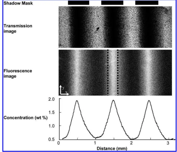
Noticeable PIPS-induced patterns of NRs evolved 20 min after the beginning of UV illumination (Figure 3). The image shows two dark NR-depleted regions, each surrounded by two noticeably brighter NR-rich fronts. As can be seen after 50 min, these fronts advanced into the UV-shielded regions toward each other and merged in a single bright region. Further increase in irradiation time resulted in NRs being in an increasingly concentrated and narrow bright zone near the center of the light-protected region. The top and middle panels of Figure 4 show the transmission and fluorescence images of the ultimate patterned film, respec-tively. The periodic variation in concentration of NRs in the film is shown in the bottom panel. The images are in anticorrelation: the NR-rich regions appear dark under visible light (transmission) and bright when fluorescence was excited withλ ) 535 nm. The local concentration of the NRs was calculated from the high-resolution fluorescence image of the film in which pixels were characterized by I(x,y,t), that is, the digital intensity registered
by the CCD camera at position (x,y) and time t. Our rationale was as follows. The average intensity I(t) should be the same at any stage of the PIPS process because when NRs diffuse to the light-protected regions of the film, their total numbers, and hence the average fluorescence intensity, should be conserved. First, we correlated the total NR concentration, C0, in the film of 1 vol
% to the average intensity of the fluorescence of the film at t ) 0. The uniformity of the fluorescence intensity across the sample (based on image analysis) was experimentally confirmed, so that
I(xi,yj,t ) 0) ) Ij(t0), where xiand yjare any arbitrary positions
in the x- and y-directions and Ij(t0) is the averaged pixel intensity
at t ) 0. Next, we experimentally determined that Ij(t0) ) Ij(t120),
where t0and t120correspond to the beginning (t ) 0 min) and
end (t ) 120 min) of the PIPS process, respectively. We related
Ij(t120) to C0and converted the local pixel intensity at 120 min
to local concentration according to eq 2
C(xi, yj, t120)
I(xi, yj, t120)
) C0
Ij(t120)
(2) where NR concentration and image fluorescence intensity at any particular position in the film after 120 min are given by C(xi,yj,t120)
and Ij(xi,yj,t120), respectively. By following these calculations, we
produced a two-dimensional concentration map of the NR-polymer patterned film, which was then averaged along the
y-direction to obtain a one-dimensional concentration profile along the x-direction. The bottom panel of Figure 4 shows that the NR-poor and NR-rich regions of the film exhibited local NR concentrations ranging between 0.5 and 2.0 vol %, respectively. To determine the orientation of NRs in the nanoparticle-rich regions of the film, we conducted two polarization-dependent spectroscopy experiments. In the first series of experiments, we measured the polarization-dependent transmission of the NR-rich regions of the film. Our convention was that the angle,θ, between the linearly polarized light and the direction of NR flow (and hence their alignment) is θ ) 0° (Figure 5, inset). For comparison purposes, this is the same direction as the x-axis in Figure 4 (middle). Conversely, atθ ) 90°, the polarization of light was perpendicular to the direction of NR flow.
Figure 5 shows the periodic variation in intensity of the transmission, T(θ), between -90°e θ e 90°. The value of T was lowest when the incident light was polarized parallel to the direction of flow of NRs (θ ) 0°) and highest when it was perpendicular (θ ) (90°). For comparison, we plotted the sinusoid Test(θ) ) -A cos(2θ), which represents the expected
variation in transmission for angleθ changing from +90°to -90°, where A is the measured amplitude of T(θ) of ∼0.007%. The two transmission curves, T(θ) and Test(θ) were phase-shifted
by 15°, corresponding to half the measured birefringence in the system (see the section titled Characterization of NRs and Patterned Films). Assuming the measured birefringence in the Figure 2.(A) TEM image of the CdSe/ZnS core-shell nanorods used
in PIPS experiments. (B) Absorbance (s) and fluorescence, PL, spectra (- - -) of CdSe (red) and CdSe/ZnS (black) nanorods dispersed in toluene solution for PLλex)430 nm.
Figure 3.Evolution of the fluorescence patterns in the NR-polymer films with increasing UV irradiation time. The scale bar refers to all images. The width of the transparent regions of the shadow mask is exaggerated for eye guiding.
system was due to the flow-oriented polymer,19we note that a 15°phase-shift corresponds to the average angle through which linearly polarized light is rotated as it traverses the sample.
In the second series of experiments, we determined alignment of NRs in the NR-rich regions of the film by measuring the
orientation-dependent absorption of polarized light. We measured four transmission spectra atθ ) 90°andθ ) 0°for the NR-rich and NR-depleted regions of the film. Intensities of polarization-dependent absorption (A90and A0) were determined using eq 1
as A0) -log
(
T 0 NR-rich ⁄ T0NR-depleted)
(3) A90) -log(
T 90 NR-rich ⁄ T90NR-depleted)
(4) where T0NR-richand T0NR-depletedare the transmission spectra atθ )0° polarization for the NR-rich and NR-depleted regions, respectively. Similarly, T90NR-richand T90NR-richare the transmission
spectra atθ ) 90°.
Next, we determined the order parameter, S, of the nanorods in the NR-rich region as20,21
S )
(
A0-A90)
⁄(
A0+A90)
(5) The electronic absorption spectrum of CdSe nanorods involves the sum of absorption into each of the five optically bright exciton fine structures.22-24The vast majority of the dipole transitionstrength is attributed to those states designated as F ) (1b and
(19) Tsvetkov, V. N. Rigid-Chain Polymers: Hydrodynamics and Optical
Properties in Solution; Consultants Bearing: New York, 1989.
(20) Fritz, K. P.; Scholes, G. D. J. Phys. Chem. B. 2003, 107, 10141.
(21) (a) Acharya, S.; Patla, I.; Kost, J.; Efrima, S.; Golan, Y. J. Am. Chem.
Soc. 2006, 128, 9294. (b) Acharya, S.; Baran Panda, A.; Efrima, S.; Golan, Y.
AdV. Mater. 2007, 19, 1105.
(22) Norris, D. J.; Efros, A. L.; Rosen, M; Bawendi, M. G. Phys. ReV. B 1996,
53, 16347.
(23) Shabaev, A.; Efros, A. L. Nano Lett. 2006, 6, 2856.
(24) Scholes, G. D. AdV. Funct. Mater. 2008, 18, 1157.
Figure 4.Transmission (top) and fluorescence (middle) images of a section of the patterned film after 120 min photoirradiation. The dashed lines overlaid on the fluorescence image represent the width of the mask used in the polarization-based spectrophotometer measurements. The corresponding concentration profile (bottom) is shown below the images. Both the transmission and fluorescence images share the same scale along the x-axis shown in the concentration profile. The width of the transparent regions of the shadow mask is exaggerated for eye guidance.
Figure 5.Variation in transmission of the NR-rich regions of the patterned film with varying polarizer angle,θ. The dotted sinusoid shows the estimated transmission, Test(θ). Inset shows schematically how θ relates to the long axis of a nanorod.
F ) 0b. The F ) 0b state is linearly polarized along the crystallographic c-axis and can therefore be used to ascertain the order parameter S according to eq 5. However, the F ) (1b states, which contribute the other ∼2/3 of the dipole strength, follow selection rules for circularly polarized light in the plane normal to the c-axis. Even when the excitation light is linearly polarized and propagating normal to the c-axis, the F ) (1b states are photoexcited by projection. A more detailed discussion of these selection rules is given elsewhere.25To obtain an accurate estimate of the order parameter, we multiplied the value of S obtained from eq 5 by a factor of 3. Figure 6 shows the spectral
variation of the corrected value of S. In the vicinity of the absorption peaks of NRs at 530 and 608 nm, the value of S increased. This effect indicated that a higher population of nanorods in NR-rich regions than in NR-poor regions was aligned along the direction of NR flow atθ ) 0°.
In summary, our work shows that photolithographic PIPS allows simultaneous patterning and alignment of semiconductor nanorods in NR-polymer composite films. The process can be used for producing large-area patterned nanostructured films with moderate alignment of nanorods in light-protected regions of the film. We stress that the alignment of NRs in the NR-rich regions occurs solely due to their flow and not because of NR-NR interactions, which were used previously at significantly higher NR concentrations.26Future experiments have to examine the
effect of aspect ratio on NR alignment and patterning. We expect that further increase in NR concentration in the films, and hence in light-protected regions, will allow for the combination of flow-induced and NR-NR-interaction-flow-induced alignment, thereby enhancing NR alignment. Second, since thermal effects may suppress NR orientation, further optimization of polymerization conditions during the PIPS process may prove beneficial in controlling NR alignment.
Acknowledgment. The authors thank NSERC Canada for
financial support of this work. The authors are grateful to Ivan Gorelikov for assistance in synthesis of semiconductor nanorods.
LA803521T
(25) Scholes, G. D.; Kim, J.; Wong, C. Y. Phys. ReV. B 2006, 73, 195325. Phys. 2004(26) Li, L.; Marjanska, M.; Park, G. H. J.; Pines, A.; Alivisatos, A. P. J. Chem., 120, 1149. Figure 6.Spectral variation in order parameter calculated from eq 5.
Peaks at 608 and 530 nm correspond to the absorption bands in CdSe NRs.