Publisher’s version / Version de l'éditeur:
Proceedings of the ASME 2016 Internal Combustion Engine Fall Technical
Conference, ICEF 2016, p. V001T03A006, 2016-10-09
READ THESE TERMS AND CONDITIONS CAREFULLY BEFORE USING THIS WEBSITE.
https://nrc-publications.canada.ca/eng/copyright
Vous avez des questions? Nous pouvons vous aider. Pour communiquer directement avec un auteur, consultez la
première page de la revue dans laquelle son article a été publié afin de trouver ses coordonnées. Si vous n’arrivez pas à les repérer, communiquez avec nous à PublicationsArchive-ArchivesPublications@nrc-cnrc.gc.ca.
Questions? Contact the NRC Publications Archive team at
PublicationsArchive-ArchivesPublications@nrc-cnrc.gc.ca. If you wish to email the authors directly, please see the first page of the publication for their contact information.
NRC Publications Archive
Archives des publications du CNRC
This publication could be one of several versions: author’s original, accepted manuscript or the publisher’s version. / La version de cette publication peut être l’une des suivantes : la version prépublication de l’auteur, la version acceptée du manuscrit ou la version de l’éditeur.
For the publisher’s version, please access the DOI link below./ Pour consulter la version de l’éditeur, utilisez le lien DOI ci-dessous.
https://doi.org/10.1115/ICEF2016-9367
Access and use of this website and the material on it are subject to the Terms and Conditions set forth at
The combustion and emissions performance of a syngas-diesel dual
fuel compression ignition engine
Guo, Hongsheng; Neill, W. Stuart; Liko, Brian
https://publications-cnrc.canada.ca/fra/droits
L’accès à ce site Web et l’utilisation de son contenu sont assujettis aux conditions présentées dans le site LISEZ CES CONDITIONS ATTENTIVEMENT AVANT D’UTILISER CE SITE WEB.
NRC Publications Record / Notice d'Archives des publications de CNRC:
https://nrc-publications.canada.ca/eng/view/object/?id=b2d8b745-6b68-41e4-9667-1ad91fbe6820 https://publications-cnrc.canada.ca/fra/voir/objet/?id=b2d8b745-6b68-41e4-9667-1ad91fbe68201
Proceedings of the ASME 2016 Internal Combustion Engine Division Fall Technical Conference ICEF2016 October 9-12, 2016, Greenville, SC, USA
ICEF2016-9367
THE COMBUSTION AND EMISSIONS PERFORMANCE OF A SYNGAS-DIESEL
DUAL FUEL COMPRESSION IGNITION ENGINE
Hongsheng Guo, W. Stuart Neill, Brian Liko
Energy, Mining and Environment Portfolio, National Research Council Canada 1200 Montreal Road, Ottawa, Ontario, Canada K1A 0R6
ABSTRACT
Remote communities in Canada heavily rely on reciprocating diesel generators for heat and power generation. These engines utilize diesel fuel that is imported at great expense and generate green-house gas (GHG) and pollutant emissions. Replacing diesel fuel in these engines by syngas derived from a thermo-chemical treatment of local renewable biomass can not only lower the fuel cost but also reduce GHG and pollutant emissions for remote communities. Besides, syngas-diesel dual fuel combustion can maintain the ability to revert back to diesel operation and therefore ensure reliable heat and power supply when syngas is not available.
In this study, the combustion and emissions performance of a syngas-diesel dual fuel engine was investigated at low and medium loads. A single cylinder direct injection diesel engine was modified to operate using a dual fuel strategy. The diesel fuel was directly injected to the cylinder, while syngas was injected into the intake port. The effects of syngas fraction and composition on energy efficiency, cylinder pressure, exhaust temperature, and combustion stability were recorded and analyzed. The emissions data, including PM, NOx, CO, and
unburned hydrocarbon, were also analyzed and reported in the paper.
The results suggest that the substitution of diesel by a syngas caused a slight decrease in brake thermal efficiency and an increase in CO emissions. The effect of a syngas on soot emissions depended on the composition and/or quality. The inert component content of a syngas significantly affected NOx
emissions in a syngas-diesel dual fuel internal combustion engine.
INTRODUCTION
Canadian remote communities heavily rely on reciprocating diesel generators for heat and power generation. These engines utilize diesel fuel that is imported at great
expense and generate significant green-house gas (GHG) and pollutant emissions. Syngas is a gaseous fuel and usually a product of gasification of biomass or municipal wastes. It consists primarily of hydrogen (H2), carbon monoxide (CO),
carbon dioxide (CO2), nitrogen (N2) and other minor
components. Partial replacement of diesel fuel in these diesel generators by syngas derived from gasification of local renewable biomass can not only reduce GHG and pollutant emissions but also lower the cost to import diesel fuel in remote communities. Dual fuel concept has been proven to be an efficient and realiable way to use gaseous fuel in compression ignition (CI) engines [1]. Using the concept of syngas-diesel dual fuel combustion can also maintain the ability to revert back to diesel operation and therefore ensure reliable heat and power supply in remote communities when syngas generation is not available.
In gaseous fuel-diesel dual fuel engines, while diesel fuel is always directly injected into the cylinder, gaseous fuel can be either directly injected into cylinder or injected into the intake manifold. Although direct injection of gaseous fuel has been successfully applied to natural gas-diesel dual fuel engines, this technology needs a complex high pressure injector. In relative terms, port injection gaseous fuel requires less modifications to convert a conventional diesel engine to a dual fuel engine. This paper discusses port injection syngas-diesel compression ignition dual fuel engine.
Although many studies have been conducted for natural gas-diesel dual fuel internal combustion engines [3-8], relatively not enough investigations have been conducted for syngas-diesel dual fuel engines. Garnier et al. [9] established a combustion predictive model and analyzed the combustion and emissions performance of a 2.8 KW syngas-diesel compression ignition dual fuel engine. The effect of H2 content in syngas on
the performance and emissions of a supercharged syngas-diesel dual fuel engine was investigated by Roy et al. [10]. They found that the engine power with higher H2-content syngas was
higher at the lower end of the optimum fuel–air equivalence ratio window and nitrogen oxide (NOx) emissions were higher.
2 Sahoo et al. [11] investigated the effect of H2/CO ratio of
syngas on the performance of a 5.2 KW CI syngas-diesel engine at a fixed diesel injection timing. Inert components in syngas have been ignored and syngas/diesel ratio was not investigated in [11]. Bika et al. [12] conducted a research on the combustion and emissions performance of a CI engine with syngas being injected into intake port, and noted that engine thermal efficiency decreased with increasing syngas/diesel ratio. Spaeth and Ciccarelli [13] investigated the performance characteristics of a diesel piloted CI engine fueled with methane and syngas, respectively, and noted that syngas produced slightly lower thermal efficiency than methane at a given equivalence ratio. Most of these syngas-diesel dual fuel studies were conducted on light-duty engines. Little information has been reported on the application of syngas in heavy-duty diesel engines that have been widely used for heat and power generation in remote communities.
The objective of this paper is to investigate the combustion and emissions performance of a heavy-duty syngas-diesel engine employing a dual fuel combustion strategy. The investigation focuses on low and medium loads with the emphasis on energy efficiency and emissions characteristics , as well as the effects of syngas composition and quality. The engine setup and experimental procedure are described first, followed by results and discussion. Finally, concluding remarks are provided.
ENGINE SETUP AND EXPERIMENTAL PROCEDURE
Engine Setup
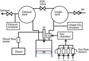
The engine used in the investigation is a modified single-cylinder version of Caterpillar’s 3400-series heavy-duty engine. The schematic of the experimental setup is shown in Fig. 1. The basic engine configuration is given in table 1.
The original engine was modified to suit for syngas-diesel dual fuel combustion. The simulated syngas was injected into the intake port by a gaseous fuel injection manifold that includes eight injectors manufactured by Alternative Fuel Systems Inc. The number of injector needed, start of syngas injection, and injection pulse width were controlled by the driven software provide by Alternative Fuel Systems Inc.
The original mechanically-actuated diesel injector was replaced by a prototype common rail fuel injector system to deliver diesel fuel directly into cylinder. The fuel rail pressure, start of diesel fuel injection and diesel injection pulse width were controlled by a data acquisition hardware (National Instruments, model PXI-1031chassis, 8184 embedded controller, and 7813 R RIO card connected to cRIO-9151 expansion chassis) and a LabVIEW-based software (Drivven Inc., Stand-Alone Direct Injector Drive System).
The syngas used was a mixture of bottled H2, CO, CO2,
and N2. The flow rates of these components were measured
separately by Bronkhorst mass flowmeters before they were mixed and injected into the engine intake port. A gas chamber was installed between the gaseous fuel flow meters and gas injector (GI) manifold to reduce the pressure osicillation.
Fig. 1 Schematic of experimental setup. Table 1 Basic engine parameters.
Parameter Value
Basic engine model Caterpillar 3401 Parent engine Caterpillar 3400 series Number of cylinder 1
Bore x stroke 137.2 mm x 165.1 mm Compression ratio 16.25:1
Displacement 2.44 liter
Number of valve 4
Combustion chamber type Quiescent Diesel fuel injection type Direct injection
Diesel fuel injector Ganser CRS AG National gas injection type Port injection
Gaseous fuel injector AFS Gs60 injectors Maximum power output 74.6 kW (@2100 rpm) An intake surge tank and an exhaust surge tank were used to help reduce pressure pulsation and simulate the turbocharging system. Compressed and temperature-controlled air was supplied to the intake surge tank to provide required intake pressure and temperature. The intake air flow rate was measured by a turbine mass flowmeter (EG&G Flow Technology, model FT-20C1NA-GEA-1). The diesel flow rate was measured by a Bronkhorst mass flowmeter.
The engine was connected to the dynamometer by a flexible drive coupling (KopFlex Inc., model Holset 3.0 Max-C “CB”). Engine loading was accomplished by an eddy-current dynamometer (Mid-West, model 1014) rated to absorb 131 kW at 2500 rpm. A load cell (Lebow, model 3169) measured the dynamometer load. Engine speed was sensed by a Hall-effect transducer. A DC electric motor was used to start and motor the engine. The engine speed and load were controlled by engine’s electronic control module and an AVL Digalog Testmate.
A water-cooled pressure transducer (Kistler Corp., model 6041A) flush-mounted in the cylinder head was used to measure cylinder pressure. The cylinder pressure data was measured for 100 consecutive engine cycles with 0.2 oCA
Exhaust
tank Intaketank
EGR valve GI Diesel Gas chamber DI Exhaust
analyzer Intake COanalyzer 2
Diesel flow meter Air Exhaust H2 CO N2CO2 Gas flow meters
3 resolution using a real-time combustion analysis system (AVL LIST GmbH, IndiModule).
A heated probe was mounted after the exhaust tank to sample the gaseous emissions. California Analytical Instruments’ series 600 gas analyzers were used to measure CO2, CO, NOx, and total unburned hydrocarbons (THC)
emissions. Soot emissions were measured by a commercialized laser-induced incandescence (LII) system (Artium LII300).
The diesel fuel used in the study was a Canadian ultra-low-sulfur diesel (ULSD) fuel. The properties of the diesel fuel are listed in table 2.
Syngas quality and composition are usually affected by gasification condition and feedstock. We investigated syngases from several gasification conditions. In this paper, we report the combustion and emissions performance of three of these syngases, syngases 1, 4 and 5. The results for syngases 2 and 3 that have compositions produced by fluidized bed are not reported in this paper. The compositions, energy contents and stoichiometric air/fuel ratio, (A/F)st, of the three investigated
syngases are shown in Table 3. Syngas 1 has a typical composition produced by a downdraft air-blown gasifier, and syngas 4 has a typical composition produced by a downdraft oxygen-blown gasifier. The difference between syngases 1 and 4 reflects the syngas quality or energy content effect. Syngas 5 is an artificially constructed one that has the same contents of inert components as syngas 1 but a different H2/CO ratio. The
difference between syngases 1 and 5 reflects the effect of H2/CO ratio of syngas. It is noted that syngases have much
lower heating values and stoichiometric air/fuel ratios than diesel fuel. Among the investigated syngases, syngas 1 has the lowest heating value and stoichiometric air/fuel ratio, while syngas 4 has the highest.
Table 2 Properties of the diesel fuel. Density, kg/m3 Cetane number LHV, MJ/kg H/C ratio (A/F)st 826.5 45.4 42.94 1.88 14.52
Table 3 Tested syngas fuels and their volume compositions and low heating values.
Syngas # H2 (%) CO (%) CO2 (%) N2 (%) LHV* (MJ/kg) (A/F)st Syngas 1 18.0 21.0 13.0 48.0 4.06 1.06 Syngas 4 34.0 48.0 12.0 6.0 10.29 2.65 Syngas 5 29.0 10.0 13.0 48.0 4.38 1.19
*
Based on low heating values of H2 and CO and composition. Experimental ConditionsDue to the significant experimental cost of using bottled gases, the investigation was conducted at 25 and 50% engine loads for syngas 1, while only at 25% load for syngases 4 and 5. The brake mean specific pressure (BMEP) being 4.05 and 8.10 bar, respectively, at 25 and 50% loads. The engine speed (N) was fixed at 910 rpm, which is the speed of the Mode 2 of
the AVL-8 Mode Heavy-Duty Cycle engine test proceedure. The relative air/fuel ratio (λ) was fixed at 2.75 and 2.17 which correspond to the fuel/air equivalence ratios of 0.36 and 0.46, respectively, at 25 and 50% loads. The intake temperature was kept as 40 oC during the experiment. The combustion phasing,
CA50 – the crank angle (CA) position at which 50% cumulative heat release was reached, was fixed at 4.0 CA degrees (after top dead center - ATDC) around which diesel-only combustion had the best brake thermal efficiency. The external exhaust gas recirculation (EGR) was not used. All tests were conducted at steady state conditions.
The syngas fraction is defined as the energy fraction coming from syngas, i.e.
syngas syngas syngas syngas syngas D D m LHV m LHV m LHV (1)
where m is mass flow rate, LHV is lower heating value. The subscripts syngas and D represent syngas and diesel, respectively. The syngas fractions investigated were 0, 25 and 50% at BMEP = 4.05 bar, and 0, 25, 50 and 60% at BMEP = 8.10 bar. Higher syngas fraction was not investigated due to the limit in the minimum diesel injection pulse width.
RESULTS AND DISCUSSION
We first present the effect of the fraction of syngas 1 on engine performance and emissions at BMEP = 4.05 and 8.10 bar. Then the effect of syngas quality is discussed by comparing the difference between the performances of syngases 1 and 5. Finally we discuss the effect of H2/CO ratio by comparing the
difference between the performances of syngases 1 and 4.
Effect of Syngas 1 Fraction on Engine Performance
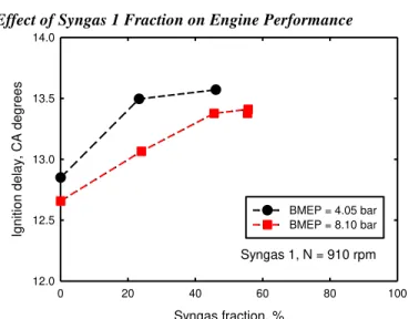
Fig. 2 Variation of ignition delay as a function of syngas 1 fraction. CA50 = 4.0 degrees (ATDC).
Figure 2 shows the variation of ignition delay, defined as the crank angle variation form the start of diesel fuel injection to the position at which 5% cumulative heat release was reached, as a function of syngas fraction for syngas 1 at BMEP = 4.05 and 8.10 bar. It is noted that the increase of syngas fraction resulted in an increase in ignition delay. Since λ was
Syngas 1, N = 910 rpm Syngas fraction, % 0 20 40 60 80 100 Ignit ion delay , CA degr ees 12.0 12.5 13.0 13.5 14.0 BMEP = 4.05 bar BMEP = 8.10 bar
4 constant during the experiment, this increase in ignition delay was because the two primary burning components of syngas, H2 and CO, have higher ignition temperatures than diesel.
Fig. 3 Variation of peak cylinder pressure as a function of syngas 1 fraction. CA50 = 4.0 degrees (ATDC). Figure 3 shows that the peak cylinder pressure slightly increased with increasing syngas fraction at both loads.
Fig. 4 Variation of intake pressure as a function of syngas 1 fraction. CA50 = 4.0 degrees (ATDC).
The variation of intake pressure as a function of syngas is displayed in Fig.4. It revealed that intake pressure slightly increased with increasing syngas fraction at a fixed speed/load/λ condition. This was simply due to the introduction of syngas to intake port. This result also suggests that if intake pressure is kept constant in a port injection syngas-diesel dual fuel engine, the increase in syngas fraction will lead to a decrease in λ at a fixed speed/load condition.
The variation of brake thermal efficiency as a function of syngas 1 fraction is displayed in Fig. 5. It indicates that the increase in syngas fraction caused a decrease in brake thermal efficiency, which is qualitatively consistent with the observation of Bika et al. [12]. This was primarily due to the increase in incomplete combustion of CO and H2, as will be
shown later. The decrease was more significant at BMEP = 4.05 bar because of the lower pressure and temperature inside cylinder which resulted in more incomplete combustion of CO and H2.
Fig. 5 Variation of brake thermal efficiency as a function of syngas 1 fraction. CA50 = 4.0 degrees (ATDC). Although not shown, we should mention that the coeifficient of variation in indicated mean effective pressure (COVIMEP) didn’t significantly change with increasing syngas
fraction. The COVIMEP never exceeded 2.0% in the experiment. Effect of Syngas 1 on Emissions
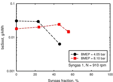
Figure 6 displays the variation of brake specific soot emissions as a function of syngas 1 fraction. It is observed that a small amount of syngas 1 caused little change or a slight increase, but further increasing syngas 1 fraction caused a decrease in soot emissions. This variation trend in soot emissions might be due to the combined effects of soot formation and oxidation rates inside cylinder when syngas 1 fraction increased.
Fig. 6 Variation of brake specific soot emissions as a function of syngas 1 fraction. CA50 = 4.0 degrees (ATDC). Since both H2 and CO, the two burning components of
syngas 1, are sooting-free fuels, soot formation in the
syngas-Syngas 1, N = 910 rpm Syngas fraction, % 0 20 40 60 80 100 P eak pre ssure , bar 60 70 80 90 100 110 BMEP = 4.05 bar BMEP = 8.10 bar Syngas 1, N = 910 rpm Syngas fraction, % 0 20 40 60 80 100 Int ake pre ssure , kP a 100 110 120 130 140 150 160 BMEP = 4.05 bar BMEP = 8.10 bar Syngas 1, N = 910 rpm Syngas fraction, % 0 20 40 60 80 100 B rake t her mal ef ficiency , % 30 33 36 39 42 45 BMEP = 4.05 bar BMEP = 8.10 bar Syngas 1, N = 910 rpm Syngas fraction, % 0 20 40 60 80 100 bsS oot , g/ kW h 0.001 0.01 0.1 BMEP = 4.05 bar BMEP = 8.10 bar
5 diesel dual fuel combustion was primarily from the combustion of diesel fuel. When syngas 1 fraction increased, the combustion temperature decreased owing to the significant content of inert components and incomplete combustion of H2
and CO, which resulted in a decrease in soot oxidation rate. Meanwhile, the increase in syngas 1 fraction also caused a decrease in soot formation rate, since all components of syngas suppressed soot formation when mixed with hydrocarbon fuels due to the combined dilution and thermal effects [14-16]. When a small amount of diesel fuel was substituted with syngas 1, the decrease in soot oxidation rate was similar to or slightly more significant than the decrease in soot formation rate, which led to little change or a slight increase in soot emissions. With further increasing syngas 1 fraction, the decrease in soot formation rate exceeded the decrease in soot oxidation rate, which caused the soot emissions to decrease.
Fig. 7 Variation of NOx emissions as a function of syngas
fraction. CA50 = 4.0 degrees (ATDC).
Figure 7 shows the variation of brake specific NOx
emissions as a function of syngas 1 fraction. The substitution of diesel by syngas 1 caused a monotonic decrease in NOx
emissions. This was due to the decrease in temperature caused by the significant amount of inert component in syngas and incomplete combustion of H2 and CO.
It is noted that the NOx emissions at BMEP = 4.05 bar was
similar to that at 8.10 bar. We should point out that this does not mean that the NOx formation rate at BMEP = 4.05 bar was
similar to that at BMEP = 8.10 bar. Although not shown due to space limit, the result did suggest that NOx concentration in the
exhaust of BMEP = 4.05 bar was much lower than in that of BMEP = 8.10 bar. The similarity in brake specific NOx
emissions at the two loads was due to the lower thermal efficiency and higher λ that resulted in higher specific exhaust flow rate at BMEP = 4.05 bar than at BMEP = 8.10 bar.
Figure 8 displays the variation of brake specific CO emissions as a function of syngas 1 fraction. At BMEP = 4.05 bar, the temperature was lower and increasing syngas fraction further reduced temperature. Meanwhile, more CO appearing in the crevice and boundary zones with increasing syngas fraction,
which resulted in more incomplete combustion of H2 and CO.
Therefore, brake specific CO emissions monotonically increased with increasing syngas fraction.
At BMEP = 8.10 bar, temperature was relatively higher than at BMEP = 4.05 bar. When a small amount of diesel fuel was substituted by syngas, CO emissions increased because CO appearing in crevice and boundary zones increased. This was similar to the situation at BMEP = 4.05 bar. However, with further increasing syngas fraction, H2 in syngas started to
enhance the combustion of CO. As a result, the combined effects of more CO in crevice and boundary zones and the enhancement of H2 for CO combustion resulted in little change
in CO emissions with further increasing syngas fraction.
Fig. 8 Variation of brake specific CO emissions as a function of syngas fraction. CA50 = 4.0 degrees (ATDC).
Effect of Syngas Quality on Energy Efficiency and Emissions
Different gasification operation conditions result in the variation in bruning components of syngas. Syngas 1 in table 3 is the one with the same composition as that of the product of a air-blow downdraft gasification, while syngas 4 is the one with the same compostion as that of the product of a oxygen-blow downdraft gasification. The primary difference between the syngases 1 and 4 is the significantly lower inert component concentration and higher heating value for syngas 4. In order to investigate the effect of this syngas quality difference on energy efficiency and emissions of the syngas-diesel dual fuel engine, the performances of syngas 1-diesel and syngas 4-diesel dual fuel combustion are compared below.
Figure 9 compares the brake thermal efficiencies of the dual fuel engine using syngases 1 and 4 at 4.05 bar. It is observed that brake thermal efficiency was higher when syngas 1 was used. This might be because more heat was released before top dead center for syngas 4. Although the combustion phasing was fixed at 4.0 CA degrees (ATDC) and the heating value of syngas 4 was higher than that of syngas 1, more heat was released before top dead center for syngas 4 because of the shorter ignition delay of syngas 4 than that of syngas 1. This caused the slightly lower brake thermal efficiency when syngas 4 was used. However, we should point out that this does not mean that syngas 1 is better than syngas 4 in terms of the effect
Syngas 1, N = 910 rpm Syngas fraction, % 0 20 40 60 80 100 bsNO x , g/ kW h 5.0 5.5 6.0 6.5 7.0 7.5 8.0 BMEP = 4.05 bar BMEP = 8.10 bar Syngas 1, N = 910 rpm Syngas fraction, % 0 20 40 60 80 100 bsCO , g/ kW h 0 10 20 30 40 50 60 70 BMEP = 4.05 bar BMEP = 8.10 bar
6 on thermal efficiency, since combustion phasing was not optimized for syngas-diesel dual fuel combustion in this investigation. Therefore, it may be needed to further optimize the combustion phasing of syngas-diesel dual fuel combustion in future.
Fig. 9 Brake thermal efficiency for syngases 1 and 4. CA50 = 4.0 degrees (ATDC).
Fig. 10 Brake specific soot emissions of syngases 1 and 4. CA50 = 4.0 degrees (ATDC).
Figure 10 displays the variation of soot emissions as a function of syngas fraction for syngases 1 and 4. We observe that soot emissions were lower when syngas 4 was used. This was primarily because of the higher temperature inside cylinder which resulted in higher soot oxidation rate when syngas 4 was used. Compared to syngas 1-diesel dual fuel combustion, the higher temperature of syngas 4-diesel dual fuel combustion was because of the significantly lower content of inert component.
Figure 11 compares the brake specific NOx emissions when
syngases 1 and 4 were used. Being different from the effect of syngas 1, the substitution of diesel by syngas 4 caused an increase in NOx emissions. Although both heating values and
stoichiometric air/fuel ratio of syngas 4 are lower than those of diesel, a simple calculation suggests that at a constant λ, the total mass (fuel + air) introduced into the cylinder for the same
energy input was lower for syngas 4 combustion than for diesel combustion. This might cause a slightly higher combustion temperature for syngas 4 combustion than for diesel combustion. Besides, because the H2 and CO in syngas 4
participated in reactions, the temperature in both premixed ignition zone and subsequent diffusion combustion zone became higher, which led to higher NOx formation rate in
combustion zones for syngas 4 combustion. These are the two factors that resulted in the increase in NOx emissions when
diesel was substituted by syngas 4.
Fig. 11 Brake specific NOx emissions for syngases 1 and 4.
CA50 = 4.0 degrees (ATDC).
Fig. 12 Brake specific CO emissions for syngases 1 and 4. CA50 = 4.0 degrees (ATDC).
Figure 12 displays the variation of brake specific CO emissions as a function of syngas fraction for syngases 1 and 4. Syngas 4 generated higher CO emissions than syngas 1 at αsyngas = 25%, but the situation slightly reversed at αsyngas= 50%.
As discussed before on the effect of syngas 1, the increase in CO emissions with increasing syngas fraction was because more CO was trapped in the cooler crevice and boundary zones, which resulted in some of the CO not being oxidized during the combustion process. When 25% diesel was substituted by
BMEP = 4.05 bar, N = 910 rpm Syngas fraction, % 0 20 40 60 80 100 B rake t her mal ef ficiency , % 30 31 32 33 34 35 36 Syngas 1 Syngas 4 Syngas fraction, % 0 20 40 60 80 100 bsS oot , g/ kW h 0.001 0.01 0.1 Syngas 1 Syngas 4 BMEP = 4.05 bar, N = 910 rpm Syngas fraction, % 0 10 20 30 40 50 60 bsNO x , g/ kW h 5 6 7 8 9 10 11 12 Syngas 1 Syngas 4 BMEP = 4.05 bar, N = 910 rpm Syngas fraction, % 0 20 40 60 80 100 bsCO , g/ kW h 0 10 20 30 40 50 60 70 Syngas 1 Syngas 4 BMEP = 4.05 bar, N = 910 rpm
7 syngas, the combustion temperature variation was not significant and the CO concentration of syngas 4 was higher than that of syngas 1. Therefore, CO emissions of syngas 4 was higher than that of syngas 1. However, with further increasing syngas fraction to 50%, syngas 4 caused temperature to increase, which enhanced the oxidation of CO compared to syngas 1. As a result, CO emissions became lower for syngas 4 substitution than for syngas 1 substitution.
Effect of H2/CO Ratio on Energy Efficiency and Emissions
Different gasification mode and feedstock may result in variation in H2/CO ratio in syngas. In order to examine the
effect of H2/CO on combustion and emissions performance in a
syngas-diesel dual fuel engine, we artificially constructed syngas 5 which had the exactly same content of inert component as syngas 1 but higher H2/CO ratio.
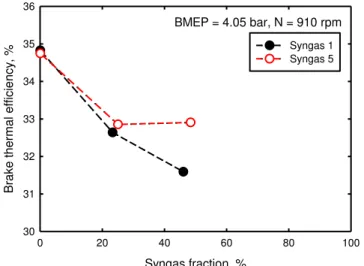
Fig. 13 Brake thermal efficiencies of syngases 1 and 5. CA50 = 4.0 degrees (ATDC).
Figure 13 compares the brake thermal efficiencies of the dual fuel combustion when syngases 1 and 5 were used. We observe that thermal efficiency was higher when diesel was substituted by syngas 5 than by syngas 1. This might be because the higher H2 concentration in syngas 5 resulted in
lower ignition temperature and therefore less incomplete combustion of H2 and CO.
Figures 14-16 compare the emissions of soot, NOx and CO
for the dual fuel combustion when syngases 1 and 5 were used. We note that the substitution of diesel by syngas 5 resulted in less soot emissions than that of syngas 1. Being different from the lower soot emissions of syngas 4 (Fig. 10), the difference between the soot emissions of syngases 1 and 5 was primarily due to the chemical effect of H2 and CO, since the combustion
temperature difference between syngases 1 and 5 was not significant. As mentioned previously, both H2 and CO are
sooting-free burning components. The mixing of them with other hydrocarbon fuels usually result in the decrease in soot emissions due to the combination of dilution and chemical effects. The dilution effect is due to the decrease in the concentration of sooting component, i.e. diesel fuel in this study. Therefore, the dilution effects of syngases 1 and 5 should
be similar at the same syngas fraction. However, CO chemically promotes soot formation while H2 chemically
suppresses soot formation when they are mixed with other hydrocarbon fuels [14,16]. Although the dilution effect is usually much more significant than the chemical effect [14-16], the combined dilution and chemical effect of CO is less significant than that of H2 in terms of decrease in soot
formation rate. As a result, the substitution of diesel by syngas 5 caused less soot emissions than that of syngas 1, since the H2/CO ratio in syngas 5 was higher.
Fig. 14 Brake specific soot emissions for syngas 1 and 5. CA50 = 4.0 degrees (ATDC).
The difference between NOx emissions of syngases 1 and 5
was not significant. This was because the variation of H2/CO
ratio caused change in not only heating value but also stoichiometric air/fuel ratio. As a result, the variation in H2/CO
ratio did not cause significant change in combustion temperature and NOx emissions.
Fig. 15 Brake specific NOx emissions of syngases 1 and 5.
CA50 = 4.0 degrees (ATDC).
CO emissions from the dual fuel combustion using syngas 5 was much lower than using syngas 1, as shown in Fig. 16. It was because the CO concentration in syngas 5 was much lower
BMEP = 4.05 bar, N = 910 rpm Syngas fraction, % 0 20 40 60 80 100 B rake t her mal ef ficiency , % 30 31 32 33 34 35 36 Syngas 1 Syngas 5 Syngas fraction, % 0 20 40 60 80 100 bsS oot , g/ kW h 0.001 0.01 0.1 Syngas 1 Syngas 5 BMEP = 4.05 bar, N = 910 rpm Syngas fraction, % 0 20 40 60 80 100 bsNO x , g/ kW h 5 6 7 8 9 10 11 12 Syngas 1 Syngas 5 BMEP = 4.05 bar, N = 910 rpm
8 than that in syngas 1 and therefore there was less incompleted CO in exhaust gas.
We should point out that the performance of a dual fuel engine is more sensitive to combustion phasing than a diesel engine because of more incomplete combustion of burning components [5]. A change in combustion phasing may cause the variation in not only fuel efficiency but also emissions performance. Therefore, it is necessary to further optimize the combustion phasing of syngas-diesel dual fuel combustion engines in future.
Fig. 16 Brake specific CO emissions of syngases 1 and 5. CA50 = 4.0 degrees (ATDC).
CONCLUSIONS
The combustion and emissions performance of a syngas-diesel dual fuel engine has been investigated at low and medium load conditions by a modified single-cylinder version of 75 KW Caterpillar’s 3400-series heavy-duty engine. Three simulated syngases with different syngas qualities and compositions were examined. The results suggest that there is good potential to partially replace diesel fuel by syngas generated by gasification of biomass to save energy cost and reduce green-house gas emissions in remote communities. However, the engine combustion and emissions performance may slightly change with replacing diesel fuel by syngas.
Following results have been obtained in this investigation: (1) The substitution of diesel fuel by a syngas usually
resulted in a slight decrease in brake thermal efficiency at low and medium load conditions. This decrease may become less or negiligible with increasing engine load;
(2) The effect of syngas on soot emissions depended on the composition and/or quality of syngas. A higher H2/CO ratio or lower inert component content in a
syngas led to lower soot emissions;
(3) The substitution of diesel fuel by syngas caused an increase in CO emissions at a low load condition. However, at a medium load condition, a small amount
of syngas substitution increased CO emissions, but further increasing syngas fraction did not significantly affect CO emissions;
(4) The inert component content of a syngas significantly affected NOx emissions in a syngas-diesel dual fuel
internal combustion engine. Generally the substitution of diesel fuel by syngas caused a decrease in NOx
emissions, but a syngas with low inert component content might increase NOx emissions.
Further investigation at higher load conditions and optimization of combustion phasing will be conducted in future.
ACKNOWLEDGMENTS
Funding for this work was provided by Natural Resources Canada through the PERD AFTER (Project AFTER16), PERD Energy End Use (project 3B03.003) and PERD BEST programs, and National Research Council Canada through the internal Bioenergy Program.
REFERENCES
[1] Wagemakers, A., Leermakers, C, 2012, "Review on the Effects of Dual-Fuel Operation, Using Diesel and Gaseous Fuels, on Emissions and Performance", SAE Technical Paper Series, SAE2012-01-0869.
[2] Jones, H.L., Taggart-Cowan, G.P., Rogak, S.N., Bushe, W.K., Munshi, S.R., Buchholz, B.A., 2005, “Source apportionment of particulate matter from a diesel pilot-ignited natural gas fuelled heavy duty DI engine”, SAE Technical Paper Series, SAE 2005-01-2149.
[3] Karim, G.A., 1980, “A Review of the Combustion Process in the Dual Fuel Engine - the Gas Diesel Engine”, Prog. Energy Combust. Sci., Vol. 6, pp. 277-285.
[4] Singh, S., Krishnan, S.R., Srinivasan, K.K., Midkiff, K.C., Bell, S.R., 2004, “Effect of pilot injection timing, pilot quantity and intake charge conditions on performance and emissions for an advanced low-pilot-ignited natural gas engine”, Int. J. Engine Research, Vol. 5, pp. 329-348.
[5] Maxey, C., Kalaskar, V., Kang, D., Boehman, A., 2013, “Impact of supplemental natural gas on engine efficiency, performance, and Emissions”, SAE Technical Paper Series, SAE 2013-01-0847.
[6] Hountalas, D.T., Rakopoulos, C.D., Rakopoilos, D.C., 2008, “Combustion and Performance Characteristics of a DI Diesel Engine Operating from Low to High Natural Gas Supplement Ratios at Various Operating Conditions”, SAE Technical Paper Series, SAE 2008-01-1392.
[7] Papagiannakis, R.G., Rakopoulos, C.D., Hountalas, D.T., Rakopoulos, D.C., 2010, “Emission Syngas fraction, % 0 20 40 60 80 100 bsCO , g/ kW h 0 10 20 30 40 50 60 70 Syngas 1 Syngas 5 BMEP = 4.05 bar, N = 910 rpm
9 characteristics of high speed, dual fuel, compression ignition engine operating in a wide range of natural gas/diesel fuel proportions”, Fuel, Vol. 89, pp. 1397-1406.
[8] Guo, H., Neill, W.S., Liko, B., “An Experimental Investigation on the Combustion and Emissions Performance of a Natural Gas – Diesel Dual Fuel Engine at Low and Medium Loads”, ASME 2015 Internal Combustion Engine Division Fall Technical Conference, ICEF2015-1041.
[9] Garnier, C., Bilcan, A., Le Corre, O., 2005, “Characterisation of a Syngas-Diesel Fuelled CI Engine”, SAE Technical Paper, SAE2005-01-1731. [10] Roy, M.M., Tomita, E., Kawahara, N., Harada, Y.,
Sakane, A., 2009, “Performance and emission comparison of a supercharged dual-fuel engine fueled by producer gases with varying hydrogen content”, International Journal of Hydrogen Energy, Vol. 34, pp. 7811-7822.
[11] Sahoo, B.B., Saha, U.K., Sahoo, N., 2011, “Effect of Load Level on the Performance of a Dual Fuel Compression Ignition Engine Operating on Syngas Fuels With Varying H2/CO Content”, Journal of Engineering for Gas Turbines and Power, Vol. 133, pp. 122802-1 ~ 122802-12.
[12] Bika, A.S., Franklin, L. and Kittelson, D., 2011, “Cycle Efficiency and Gaseous Emissions from a Diesel Engine Assisted with Varying Proportions of Hydrogen and Carbon Monoxide (Synthesis Gas)”, SAE Technical Paper, SAE 2011-01-1194.
[13] Spaeth, C., Ciccarelli, G., 2012, “Performance of a diesel fuel piloted syngas compression ignition engine”, Proceedings of Combustion Institute - Canadian Section Spring Technical Meeting, Toronto, Canada.
[14] Guo, H., Thomson, K.A., Smallwood, G.J., 2009, “On the Effect of Carbon Monoxide Addition on Soot Formation in a Laminar Ethylene/Air Coflow Diffusion Flame”, Combustion and Flame, Vol. 156, pp.1135–1142.
[15] Guo, H., Smallwood, G.J., 2008, “A Numerical Study on the Influence of CO2 Addition on Soot Formation in an Ethylene/Air Diffusion Flame”, Combust. Sci. Technol., Vol. 180, pp.1695–1708.
[16] Guo, H., Liu, F., Smallwood, G.J., Gülder, Ö.L, 2006, “A Numerical Study on the Influence of Hydrogen Addition on Soot Formation in a Laminar Ethylene-Air Diffusion Flame”, Combustion and Flame, Vol. 145, pp.324-338.