Publisher’s version / Version de l'éditeur:
AIP Advances, 6, 9, pp. 095009-1-095009-8, 2016-09
READ THESE TERMS AND CONDITIONS CAREFULLY BEFORE USING THIS WEBSITE. https://nrc-publications.canada.ca/eng/copyright
Vous avez des questions? Nous pouvons vous aider. Pour communiquer directement avec un auteur, consultez la
première page de la revue dans laquelle son article a été publié afin de trouver ses coordonnées. Si vous n’arrivez pas à les repérer, communiquez avec nous à [email protected].
Questions? Contact the NRC Publications Archive team at
[email protected]. If you wish to email the authors directly, please see the first page of the publication for their contact information.
NRC Publications Archive
Archives des publications du CNRC
This publication could be one of several versions: author’s original, accepted manuscript or the publisher’s version. / La version de cette publication peut être l’une des suivantes : la version prépublication de l’auteur, la version acceptée du manuscrit ou la version de l’éditeur.
For the publisher’s version, please access the DOI link below./ Pour consulter la version de l’éditeur, utilisez le lien DOI ci-dessous.
https://doi.org/10.1063/1.4962964
Access and use of this website and the material on it are subject to the Terms and Conditions set forth at
Multi-parameter sensor based on random fiber lasers
Xu, Yanping; Zhang, Mingjiang; Lu, Ping; Mihailov, Stephen; Bao, Xiaoyi
https://publications-cnrc.canada.ca/fra/droits
L’accès à ce site Web et l’utilisation de son contenu sont assujettis aux conditions présentées dans le site LISEZ CES CONDITIONS ATTENTIVEMENT AVANT D’UTILISER CE SITE WEB.
NRC Publications Record / Notice d'Archives des publications de CNRC:
https://nrc-publications.canada.ca/eng/view/object/?id=78136446-69a9-4fba-87a4-7d054cbba16d https://publications-cnrc.canada.ca/fra/voir/objet/?id=78136446-69a9-4fba-87a4-7d054cbba16d
Multi-parameter sensor based on random fiber lasers
Yanping Xu, Mingjiang Zhang, Ping Lu, Stephen Mihailov, and Xiaoyi BaoCitation: AIP Advances 6, 095009 (2016); doi: 10.1063/1.4962964
View online: http://dx.doi.org/10.1063/1.4962964
View Table of Contents: http://scitation.aip.org/content/aip/journal/adva/6/9?ver=pdfcov
Published by the AIP Publishing
Articles you may be interested in
A preliminary study of multi-parameter POD curves for a guided waves based SHM approach to lightweight materials
AIP Conf. Proc. 1706, 030018 (2016); 10.1063/1.4940490
Lyapunov exponents for multi-parameter tent and logistic maps
Chaos 21, 043104 (2011); 10.1063/1.3645185
Multi‐Parameter Exponentially Fitted, P‐stable Obrechkoff Methods
AIP Conf. Proc. 1389, 217 (2011); 10.1063/1.3636706
Multi‐parameters Characterization of Electromigration Noise in Metal Interconnection
AIP Conf. Proc. 1129, 637 (2009); 10.1063/1.3140555
Sensor node development of a low power, high data rate Multi-Parameter Sensor (MPS) system
AIP ADVANCES 6, 095009 (2016)
Multi-parameter sensor based on random fiber lasers
Yanping Xu,1Mingjiang Zhang,1,2Ping Lu,3Stephen Mihailov,3 and Xiaoyi Bao1,a
1Department of Physics, University of Ottawa, Ottawa, Ontario K1N 6N5, Canada 2Institute of Optoelectronic Engineering, Department of Physics and Optoelectronics,
Taiyuan University of Technology, Taiyuan 030024, China
3National Research Council Canada, Ottawa, Ontario K1A 0R6, Canada
(Received 5 July 2016; accepted 5 September 2016; published online 13 September 2016)
We demonstrate a concept of utilizing random fiber lasers to achieve multi-parameter sensing. The proposed random fiber ring laser consists of an erbium-doped fiber as the gain medium and a random fiber grating as the feedback. The random feedback is effectively realized by a large number of reflections from around 50000 femtosec-ond laser induced refractive index modulation regions over a 10cm standard single mode fiber. Numerous polarization-dependent spectral filters are formed and super-imposed to provide multiple lasing lines with high signal-to-noise ratio up to 40dB, which gives an access for a high-fidelity multi-parameter sensing scheme. The num-ber of sensing parameters can be controlled by the numnum-ber of the lasing lines via input polarizations and wavelength shifts of each peak can be explored for the simul-taneous multi-parameter sensing with one sensing probe. In addition, the random grating induced coupling between core and cladding modes can be potentially used for liquid medical sample sensing in medical diagnostics, biology and remote sensing in hostile environments. © 2016 Author(s). All article content, except where
oth-erwise noted, is licensed under a Creative Commons Attribution (CC BY) license (http://creativecommons.org/licenses/by/4.0/).[http://dx.doi.org/10.1063/1.4962964]
In optical materials that appear opaque, multiple scattering usually takes place thousands of times in a random fashion for the penetrated light rays before they exit. Based on this type of propagation randomness, random lasers have been extensively studied and researched since the first time the laser action was obtained in disordered structures as proposed by Ambartsumyan, etc. in 1966.1Over the past several decades, random lasers have been observed and demonstrated in various random media,2–10including crystal powder material, laser dye with nanoparticles, rare-earth pow-ders, semiconductor powder, polymer films with silver nanoparticles and even dye treated human tissues. The unique emission spectra and cost-effective features of random lasers make themselves excellent candidates in applications of environment lighting,11remote sensing,12speckle-free imag-ing,13document coding,14and medical diagnostics.10,15The directionality and lasing efficiency of random lasers could be improved and optimized by replacing the disordered medium with optical fibers, namely the random fiber laser (RFL). The 1-D optical fiber waveguide provides good confine-ment in the transverse directions of the light rays trapped inside and effective one-dimension random feedback. RFLs have been realized using Er-doped fiber gain, Raman gain, and Brillouin gain with random feedback induced by Rayleigh scattering,16–21or artificially induced randomness such as a photonic crystal fiber filled with a suspension structure,22Bragg gratings in rare-earth doped fiber,23 and polymer optical fiber.24Either in-coherent or coherent lasing outputs have been observed in these random lasing systems, with lasing spectra of bell-shaped peaks as broad as terahertz level25or even narrow spikes as sharp as sub-kilohertz.26,27RFLs based on the Raman gain has been widely used in many fields, including providing the distributed Raman amplification with lower effective noise and good stability in telecommunication applications,28,29remote temperature point-based sensing
aElectronic mail:[email protected].
095009-2 Xu et al. AIP Advances 6, 095009 (2016)
systems up to 300km,30,31and extending the sensing range in the distributed sensing systems.32,33 The Brillouin gain based RFL has been utilized in spectral characterization for lasing linewidth measurements21as well as random bit generation.34
In this letter, a multi-parameter sensor based on the RFL composed of a fiber ring laser with Er-doped gain and an injection of a fiber random grating is proposed and experimentally demon-strated. The random fiber grating consisting of around 50000 index modification spots induced by femtosecond laser with a randomly varying separation in the scale of several microns provides highly disordered scattering feedback, which could be amplified by the Er-doped gain with wide bandwidth. The resultant sub-nanometer sharp spectral peaks associated with high-Q resonances are utilized for multi-parameter sensing. By controlling the polarization state of the light to be scattered by the random grating, selective modes could be amplified as a result of lasing lines with wide spectral separations. Different from fixed cavity laser that can only support one peak or multiple peaks with integer numbers of longitudinal modes, these multiple lasing lines are contributed by the multiple random modes which originate from different Fabry-Perot (FP) cavities formed by the scattering centers along the random grating sample. Furthermore the randomly distributed refractive index modification spots introduce random birefringence along the sample, making the FP filters polar-ization dependent. Hence the lasing lines have different strain and temperature dependence due to different index modifications as well as dispersion effects. With the sharp peaks of high-Q value in the RFL, simultaneous multi-parameter measurements could be realized with better resolution compared with the single-pass random grating sensor.35In a previous work where a Raman random fiber laser with multiple lasing lines was achieved based on multiple fiber Bragg gratings (FBG) and Rayleigh feedback from a 22km long optical fiber.36Each lasing line is potentially able to be used for sensing depending on the temperature response of the FBG reflectors. However, the proposed random fiber laser based sensor possesses more advantages over the previous scheme such as same sensing head for multi-parameter sensing, higher SNR of the lasing lines, simple and cost-effective fabrication process without the need of phase mask or critical alignment and vibration control in the FBG manufacturing process, higher compactness and lower power consumption.
The fiber random grating samples are inscripted by using a femtosecond Ti:sapphire regenerative amplifier (Spitfire, Coherent) operating at a wavelength of 800 nm with a repetition rate of 100 Hz and a pulse duration of 80 fs as shown schematically in Fig.1. A beam reducer was used to reduce the beam width to match the open aperture of the objective (50×/0.6, Nikon). The dichroic mirror was used to guide the laser beam into the objective which was fixed on a translation stage driven by a piezo positioning system, which allows Z-direction focusing and random dithering along the fiber axis with a maximum displacement of 2.5 µm. A standard single-mode fiber (Corning SMF-28) was clamped by fiber holders on two translation stages, which are able to move along the fiber axis with a speed of 100 µm/s during the fabrication process. A CCD camera after the dichroic mirror was used to monitor the fiber alignment and the micro-machining process during the fabrication of the optical fiber random gratings. A grating plane normal to the fiber axis of induced index change with a diameter of ∼10 µm and a thickness of less than 1 µm across the fiber core was produced by a single femtosecond laser pulse with the combination of the cylindrical lens and the objective. The optical image of the fiber random grating sample is shown in Fig.1. The index modification was processed spot by spot with a spacing of d randomly varied between 0 µm and 3.5 µm with a pulse energy of 1.0 µJ. The spacing randomness was predetermined by the random number generated by a computer and stored for repeatable uses afterwards. Around 50000 spots were made along the 10 cm long fiber sample. The main purpose of producing such a large number of modification spots is to increase the randomness of the feedback from the random grating as well as to enhance the random feedback strength.The bottom figure of Fig.1shows typical reflection (blue) and transmission (red) spectra of the random grating sample. It is illustrated that only a small proportion of the incident light would be reflected backward at the spots with localized changes in the refractive indices. Higher attenuation in the transmission spectrum is due to the significant refraction and absorption loss at the non-uniform index modification regions. It is also noted that the interference pattern is hardly observed in the transmission spectrum as the energies of the transmitted cladding modes are relatively small compared to that of the transmitted core mode, leading to a minimum visibility in the transmitted interference spectrum.
095009-3 Xu et al. AIP Advances 6, 095009 (2016)
FIG. 1. Experimental setup of the femtosecond laser based micro-machining system for random grating fabrication with an example of reflection and transmission spectra (bottom figure) of a random grating sample.
The experimental setup for the random grating based Erbium-doped fiber ring laser is shown in Fig.2. A C-band Erbium-doped fiber amplifier (EDFA) ranging from 1528nm to 1565nm was used as the laser seed and gain medium. The amplified spontaneous emission (ASE) from the EDFA then passed through the isolator and the first polarization controller (PC 1). The isolator was placed next to the EDFA to avoid the damage induced by the backflow of the lasing light and the PC 1 was used to adjust the input polarization of the light before it was sent to the random grating sample through an optical circulator. The enlarged figure shows a schematic drawing of the light scattering in the random grating. The randomly backscattered light from the random grating was guided to another
FIG. 2. The schematic experimental setup of the random grating based Erbium-doped fiber ring laser; the magnified figure is a schematic illustration of the backscattering within the random grating sample; EDFA: Erbium-doped fiber amplifier; PC: Polarization controller.
095009-4 Xu et al. AIP Advances 6, 095009 (2016)
PC followed by an optical coupler with a ratio of 95/5. 95% of the light was sent back to the ring resonator, while 5% was used for detection.
As shown in Fig.2, the distributed backscattered light from the random grating is induced by the randomly distributed scattering centers which are generated by random index modification. These frozen scattering centers could be considered fully deterministic in time, but their amplitudes and locations are randomly distributed. The backscattered light at the input end of the random grating (Port 3 of the circulator) is the summation of all the scattered light waves from different scattering centers. Then the backscattered light is re-amplified by the EDFA and the re-amplified light is once again backscattered by the random grating. The lasing process is established through the interference between lights with different loop trips along the ring resonator. In simulations, only the amplified spontaneous emissions from the EDFA and the light after the first round trip are taken into account for the interference for simplicity. If the amplified spontaneous emissions are denoted by EASE, the
light after the round trip through the random grating could be expressed as
ER= N X i=1 EASEAiexp(−i 4πnzi λ ) (1)
Where N is the total number of the scattering centers, Ai and zi are the reflection coefficient and
position of each scattering center, n is the refractive index of optical fiber, λ is the wavelength of the light, c is the light speed in vacuum. The backscattered light is then amplified by the EDFA and re-sent to the random grating sample. Therefore considering the phase term introduced by the light travelling outside the random grating length, the ASE after one loop could be written as
E′ ASE= exp(−i 2πnL λ ) N X i=1 GEASEAiexp(−i 4πnzi λ ) (2)
Where L is the length of the loop, and G is the gain value provided by the EDFA. It could be seen from the above equations that the amplitude and phase of the ASE after one loop trip are determined by the spectrum of the initial ASE, the position and reflection coefficient of each scattering center,
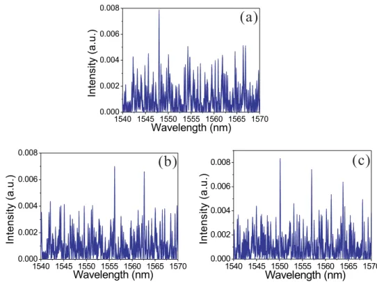
FIG. 3. Simulated lasing output of the random grating based Erbium-doped fiber ring laser with different input polarizations: (a) one lasing line, (b) two lasing lines, and (c) multiple lasing lines.
095009-5 Xu et al. AIP Advances 6, 095009 (2016)
and the loop length. Thus the constructive interference between E′
ASEand EASEcan be obtained by
computing the product of <E′
ASE·EASE>. However, when the polarization of the input light is changed
by adjusting PC1, the previous set of scattering centers that provide the effective backscattering is no longer effective due to the polarization mismatch. The reflection coefficients and positions of the scattering centers for the input light with new polarization are re-distributed. In this circumstance, both Aiand ziin the above equations will follow a new random distribution, leading to a brand new
spectrum of the light wave after first loop trip.
Fig.3shows the simulated lasing output of the random grating based Erbium-doped fiber ring laser with different input polarizations. In the simulations, the length of the loop is set to 50m and around 500 scattering centers were randomly generated along the 10cm long modified SMF. Considering the birefringent effect of the randomly induced index change by femtosecond laser, the polarization influence of the input ASE sent to the random grating sample is simulated by changing the random distribution of the locations and reflection coefficients of the scattering centers. E′
ASEis
calculated as a function of the spectrum of the ASE based on Eq. (2). The interference between the
E′
ASEand EASEis computed as shown in Fig.3(a)(b)(c)with different input polarizations. It is noted
that the output lasing lines strongly depend on the random distribution of the scattering centers and the polarization induced re-distribution of the scattering centers. Multiple lasing lines with large spectral separations could be observed as a result of multiple resonances of the constructive interference between E′
ASEand EASE.
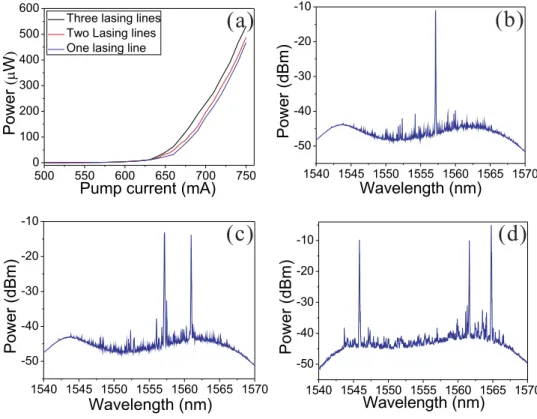
In the experiments, the random grating sample was placed in an aluminous soundproof box to protect the backscattering light from the environmental disturbances. The output power of the EDFA was gradually increased to reach the threshold and activate the ring laser. A portion of the ring laser output from the 5% port of the coupler was sent to an Optical Spectral Analyzer (OSA) for spectrum characterization. The polarization of the input light was adjusted by controlling the PC1. The laser output powers as the function of the EDFA current were plotted in Fig.4(a) with different input polarization states. Fig.4(b)(c)(d)show the corresponding measured lasing spectra of
FIG. 4. (a) Lasing thresholds indicated by the laser output power as a function of pump current for different numbers of emitted lasing lines. Experimental results of the lasing spectra with different input polarizations: (b) one lasing line, (c) two lasing lines, and (d) three lasing lines.
095009-6 Xu et al. AIP Advances 6, 095009 (2016)
the random grating based fiber ring laser with different numbers of lasing lines. The EDFA currents for all cases were set above the threshold values. By changing the input polarization state of the ASE to the random grating sample, the outcome lasing spectra respond with different numbers of lasing lines associated with different random modes. The randomly distributed scattering centers induced by the femtosecond laser micro-machining introduce random birefringence along the fiber and form numerous polarization dependent spectral filters which are superimposed with each other, leading to specific coherent resonant lasing lines. The threshold for more lasing lines has a tendency to decrease. It is also notified that the resonant lasing lines are built up with very high signal-to-noise ratio up to 40dB, which is limited by the gain provided by the EDFA. The separation of these lasing lines could be as large as about 19nm, which is due to the spectral filtering effect of the FP filters formed by the closely separate scattering centers, that is, the resonant wavelength is selected by the polarization-dependent filters. Because of different spacing among the index modification spots, multiple lasing lines selected by different FP cavities have different strain and temperature dependence due to different index modulations at different locations, which gives access to the parameter measurement using the RFL imposed by the random grating feature.
The wavelength responses of the multiple lasing lines could be utilized for measuring parameters which influence the phase differences of those FP filters formed along the random grating sample. The phase changes are different for FP cavities at different locations and also impacted by external disturbances with different extents at different wavelengths, leading to distinct wavelength shifts among the resultant multiple lasing lines. In experiments, temperature measurements were conducted by placing the random grating sample into an oven. The output lasing spectra at each temperature were recorded when the temperature inside the oven remained stable. To characterize the strain sensitivity of the proposed sensor, the two ends of the random grating were anchored horizontally between a motorized translational stage and a stationary stage. The system is capable of stretching the sensor longitudinally by controlling the motorized stage along the axis of the random grating with a sequential strain step of 100 µε. As shown in Fig.5(a), two lasing lines at 1545.4nm and 1564.4nm are selected for monitoring the spectral shifts responding to the temperature and strain variations. It could be seen from the figure that both lines experience significant spectral shifts when
FIG. 5. (a) Illustration of lasing line shifts as a result of temperature change; wavelength shift calibration results of temperature and strain measurements for Line 1(b) and Line 2 (c).
095009-7 Xu et al. AIP Advances 6, 095009 (2016)
the surrounding temperature of the random grating was increased from 28◦
C to 77◦
C. It was also noticed that in the experiments the variation in the peak intensities of the lasing lines and generation of extra lasing lines were observed when relatively high temperature or large strain was applied on the sensor. However, if the external disturbances are not so large that the induced refractive index change is quite small compared to the femtosecond laser induced refractive index modification which is in the order of 10-4∼10-5 in the random grating, the target lasing lines still remain there for the spectral shift monitoring. More details of the temperature and strain measurements are depicted in Fig.5(b)(c), in which the wavelength shift-related temperature coefficients for both lasing lines are 10.0pm/◦
C and 10.4pm/◦
C and the wavelength shift-related strain coefficients for both lasing lines are 1.60pm/µε and 1.53pm/µε, respectively.
A character matrix MT,ǫ is defined to represent the sensing performance of the lasing lines in the random grating based fiber ring laser by
∆λ1 ∆λ2 = MT,ε ∆T ∆ε = CT1 Cε 1 CT 2 C ε 2 ∆T ∆ε = " 10.0 1.60 10.4 1.53 # ∆T ∆ε (3)
where ∆λ1 and ∆λ2represent the spectral shift of Line 1 and 2 induced by temperature and strain variations. C1T, Cε
1, C
T
2, andC ε
2 are the temperature and strain coefficients of Line 1 and 2, respectively. The character matrix MT,ǫ can be used to simultaneously determine the variations in the temperature and strain from the spectral shifts of lasing lines. Error analysis for the measurement of multiple parameters is given by:37
δT δε = M′ T,ε ∆ δλ1 δλ2 (4)
where δT and δε are the errors of temperature and strain, ∆ is the determinant of MT,ε, MT′,ε, is the adjugate matrix of MT,ε, and δλ1and δλ2are the errors of the spectral shift of lasing lines. According to the error analysis for simultaneous multi-parameter measurements, the calculated maximum errors of temperature and strain measurements are 2.3◦
C and 15.2µε.
In summary, a multi-parameter fiber-optic sensor based on random fiber laser has been proposed and experimentally demonstrated. A polarization sensitive random grating fabricated by femtosecond laser micro-machining was injected to an Erbium-doped fiber ring laser, generating multiple high-fidelity lasing lines. By choosing different lasing lines and monitoring their spectral responses to the external disturbances, multi-parameter sensing could be realized. The sensing error is able to be further improved by replacing with a gain of broader bandwidth, so as to yield more distinct responses to the varied parameters. The innovative concept of utilizing the random laser for parameter quantification could be extended to applications in medical diagnostics, biology and remote sensing in hostile environments by substituting the random grating medium with target-oriented materials.
The authors are thankful to the Natural Sciences and Engineering Research Council of Canada (NSERC) Discovery Grant and Canada Research Chair Program (CRC in Fiber Optics and Photonics).
1R. V. Ambartsumyan, N. G. Basov, P. G. Kryukov, and V. S. Letokhov,IEEE J. Quantum Electron.2(9), 442–446 (1966). 2S. Gottardo, O. Cavalieri, O. Yaroshchuk, and D. S. Wiersma,Phys. Rev. Lett.93(26), 263901 (2004).
3J. Zhu, W. Li, Y. Sun, J. Lu, X. Song, C. Chen, Z. Zhang, and Y. Su,Appl. Phys. Lett.106(19), 191903 (2015). 4N. M. Lawandy, R. M. Balachandran, A. S. L. Gomes, and E. Sauvain,Nature368(6470), 436–438 (1994). 5G. R. Williams, S. B. Bayram, S. C. Rand, T. Hinklin, and R. M. Laine,Phys. Rev. A65(1), 013807 (2002).
6H. Cao, Y. G. Zhao, S. T. Ho, E. W. Seelig, Q. H. Wang, and R. P. H. Chang,Phys. Rev. Lett.82(11), 2278–2281 (1999). 7M. Sasaki, Y. Inose, K. Ema, T. Ohtsuki, H. Sekiguchi, A. Kikuchi, and K. Kishino,Appl. Phys. Lett.97, 151109 (2010). 8S. F. Yu, C. Yuen, S. P. Lau, W. I. Park, and G.-C. Yi,Appl. Phys. Lett.84(17), 3241–3243 (2004).
9X. Meng, K. Fujita, Y. Zong, S. Murai, and K. Tanaka,Appl. Phys. Lett.92(20), 201112 (2008). 10R. C. Polson and Z. V. Vardeny,Appl. Phys. Lett.85(7), 1289–1291 (2004).
11J. Dubois and S. la Rochelle, US Patent 5,966,227 (1999). 12D. S. Wiersma and S. Cavalieri,Nature414, 708–709 (2001).
13B. Redding, M. A. Choma, and H. Cao,Nat. Photonics6(6), 355–359 (2012).
14D. S. Wiersma, “The physics and applications of random lasers,”Nat. Phys.4(5), 359–367 (2008).
15R. Choe, A. Corlu, K. Lee, T. Durduran, S. D. Konecky, M. Grosicka-Koptyra, S. R. Arridge, B. J. Czerniecki, D. L. Fraker,
A. DeMichele, B. Chance, M. A. Rosen, and A. G. Yodh,Med. Phys.32, 1128–1139 (2005).
16S. K. Turitsyn, S. A. Babin, A. E. El-Taher, P. Harper, D. V. Churkin, S. I. Kablukov, J. D. Ania-Casta˜n´on, V. Karalekas,
095009-8 Xu et al. AIP Advances 6, 095009 (2016)
17A. A. Fotiadi,Nat. Photonics4(4), 204–205 (2010).
18I. D. Vatnik, D. V. Churkin, and S. A. Babin,Opt. Express20(27), 28033–28038 (2012).
19Z. N. Wang, Y. J. Rao, H. Wu, P. Y. Li, Y. Jiang, X. H. Jia, and W. L. Zhang,Opt. Express20(16), 17695–17700 (2012). 20T. Zhu, X. Bao, and L. Chen,J. Lightwave Technol.29(12), 1802–1807 (2011).
21Y. Xu, D. Xiang, Z. Ou, P. Lu, and X. Bao,Opt. Lett.40(9), 1920–1923 (2015).
22C. J. de Matos, L. de S Menezes, A. M. Brito-Silva, M. A. Martinez G´amez, A. S. Gomes, and C. B. de Ara´ujo,Phys. Rev.
Lett.99(15), 153903 (2007).
23M. Gagn´e and R. Kashyap, Opt. Express 17(21), 19067–19074 (2009).
24Z. Hu, B. Miao, T. Wang, Q. Fu, D. Zhang, H. Ming, and Q. Zhang,Opt. Lett.38(22), 4644–4647 (2013).
25S. K. Turitsyn, S. A. Babin, D. V. Churkin, I. D. Vatnik, M. Nikulin, and E. V. Podivilov,Phys. Rep.542, 133–193 (2014). 26M. Pang, X. Bao, and L. Chen,Opt. Lett.38, 1866–1868 (2013).
27M. Pang, X. Bao, L. Chen, Z. Qin, Y. Lu, and P. Lu,Opt. Express21, 27155–27168 (2013).
28D. V. Churkin, S. Sugavanam, I. D. Vatnik, Z. N. Wang, E. V. Podivilov, S. A. Babin, Y. J. Rao, and S. K. Turitsyn,
Adv. Opt. Photonics7(3), 516–569 (2015).
29X.-H. Jia, Y.-J. Rao, F. Peng, Z.-N. Wang, W.-L. Zhang, H.-J. Wu, and Y. Jiang,Opt. Express21, 6572–6577 (2013). 30Z. N. Wang, Y. J. Rao, H. Wu, P. Y. Li, Y. Jiang, X. H. Jia, and W. L. Zhang,Opt. Express20, 17695–17700 (2012). 31H. Martins, M. B. Marques, and O. Fraz˜ao,Opt. Express19, 18149–18154 (2011).
32X.-H. Jia, Y.-J. Rao, Z.-N. Wang, W.-L. Zhang, C.-X. Yuan, X.-D. Yan, J. Li, H. Wu, Y.-Y. Zhu, and F. Peng,Opt. Express
21, 21208–21217 (2013).
33Z. N. Wang, J. J. Zeng, J. Li, M. Q. Fan, H. Wu, F. Peng, L. Zhang, Y. Zhou, and Y. J. Rao,Opt. Lett.39, 5866–5869 (2014). 34D. Xiang, P. Lu, Y. Xu, S. Gao, L. Chen, and X. Bao,Opt. Lett.40(22), 5415–5418 (2015).
35Y. Xu, P. Lu, S. Gao, D. Xiang, P. Lu, S. Mihailov, and X. Bao,Opt. Lett.40(23), 5514–5517 (2015).
36A. E. El-Taher, P. Harper, S. A. Babin, D. V. Churkin, E. V. Podivilov, J. D. Ania-Castanon, and S. K. Turitsyn,Opt. Lett.
36(2), 130–132 (2011).

![[PDF] Apprendre ADO.Net par la pratique cours et exercices complet | Cours visual basic](data:image/gif;base64,R0lGODlhAQABAIAAAP///wAAACH5BAEAAAAALAAAAAABAAEAAAICRAEAOw==)