Publisher’s version / Version de l'éditeur:
Vous avez des questions? Nous pouvons vous aider. Pour communiquer directement avec un auteur, consultez la
première page de la revue dans laquelle son article a été publié afin de trouver ses coordonnées. Si vous n’arrivez pas à les repérer, communiquez avec nous à PublicationsArchive-ArchivesPublications@nrc-cnrc.gc.ca.
Questions? Contact the NRC Publications Archive team at
PublicationsArchive-ArchivesPublications@nrc-cnrc.gc.ca. If you wish to email the authors directly, please see the first page of the publication for their contact information.
https://publications-cnrc.canada.ca/fra/droits
L’accès à ce site Web et l’utilisation de son contenu sont assujettis aux conditions présentées dans le site
LISEZ CES CONDITIONS ATTENTIVEMENT AVANT D’UTILISER CE SITE WEB.
5th International Conference on Structural Health Monitoring of Intelligent
Infrastructure (SHMII-5) [Proceedings], 2011-12-11
READ THESE TERMS AND CONDITIONS CAREFULLY BEFORE USING THIS WEBSITE. https://nrc-publications.canada.ca/eng/copyright
NRC Publications Archive Record / Notice des Archives des publications du CNRC :
https://nrc-publications.canada.ca/eng/view/object/?id=0ca1a87e-2265-4b44-bb49-dcddf82d2395 https://publications-cnrc.canada.ca/fra/voir/objet/?id=0ca1a87e-2265-4b44-bb49-dcddf82d2395
NRC Publications Archive
Archives des publications du CNRC
This publication could be one of several versions: author’s original, accepted manuscript or the publisher’s version. / La version de cette publication peut être l’une des suivantes : la version prépublication de l’auteur, la version acceptée du manuscrit ou la version de l’éditeur.
Access and use of this website and the material on it are subject to the Terms and Conditions set forth at
Field monitoring of reinforced concrete bridge barriers reinforced with
GFRP and steel bars
Field monitoring of reinforced
concrete bridge barriers
reinforced with GFRP and steel
bars
Claude, J.-F; Ahmed, E.; Cusson, D.; Benmokrane, B.
NRCC-54572
A version of this document is published in5th International Conference on Structural Health Monitoring of
Intelligent Infrastructure (SHMII-5), Cancun, Mexico, December 11-15, 2011
The material in this document is covered by the provisions of the Copyright Act, by Canadian laws, policies, regulations and international agreements. Such provisions serve to identify the information source and, in specific instances, to prohibit reproduction of materials without written permission. For more information visit http://laws.justice.gc.ca/en/showtdm/cs/C-42
Les renseignements dans ce document sont protégés par la Loi sur le droit d’auteur, par les lois, les politiques et les règlements du Canada et des accords internationaux. Ces dispositions permettent d’identifier la source de l’information et, dans certains cas, d’interdire la copie de documents sans permission écrite. Pour obtenir de plus amples renseignements : http://lois.justice.gc.ca/fr/showtdm/cs/C-42
- 1 -
Field monitoring of reinforced concrete bridge
barriers reinforced with GFRP and steel bars
Jean-Francois Claude
University of Sherbrooke, Canada
Ehab Ahmed
University of Sherbrooke, Canada
Daniel Cusson
Institute for Research in Construction,
NRC, Canada
Brahim Benmokrane
University of Sherbrooke, Canada
Through a collaboration project between the Ministry of Transportation of Quebec
(MTQ) and the University of Sherbrooke, the field monitoring of GFRP and steel
reinforced concrete barriers is being conducted. The barriers are constructed on
6-lane concrete bridge using high performance concrete with a compressive strength of
50 MPa after 28 days.
The barrier under consideration was constructed on the 410-overpass bridge on the
Highway 410 separating the 6-lane bridge into three lanes in each direction. The
field monitoring included two sections of 23 m-long and 24 m-long. The first section
(24 m-long) was reinforced with GFRP bars and the second one (23-m long) was
reinforced with galvanized steel bars. The main objective was to monitor the crack
initiation and propagation as well as the strain evolution in both reinforced sections.
Besides, the effect of early age shrinkage and cracking of the high performance
concrete was captured thought the monitoring.
The GFRP bars were instrumented with fibre-optic sensors (FOS) at different
locations along the barrier length while the steel bars were instrumented with
vibrating wire strain gauges (VWSG). Thermometers (TH-T) were also used for
temperature measurements. In addition to the FOS and the vibrating wire strain
gauges, electrical resistance strain gauges (ESG) were also used for additional
measurements. The vibrating wire sensors and thermometers were connected to two
multiplexer and a Datalogger type CR10X to capture their readings while the FOS
sensors were connected to a 16-channel DMI unit to capture and store their readings.
The readings of the ESG, however, were captured using the P-3500 readout unit.
The results and the general discussion of the measured readings as well as some
concluding remarks are presented.
Corresponding author’s email:
Ehab.Ahmed@USherbrooke.ca
Field monitoring of reinforced concrete bridge barriers reinforced
with GFRP and steel bars
- 2 -
1
Master Student, Dept. of Civil Engineering, University of Sherbrooke, Quebec, Canada
2
Postdoctoral Fellow, Dept. of Civil Engineering, University of Sherbrooke, Quebec, Canada
3
Institute for Research in Construction, NRC, Ottawa, Ontario, Canada
4
Canada and NSERC Research Chair Professor, Dept. of Civil Engineering, University of Sherbrooke, Sherbrooke, Quebec, Canada
ABSTRACT: Through a collaboration project between the Ministry of Transportation of Quebec (MTQ) and the University of Sherbrooke, the field monitoring of GFRP and steel reinforced concrete barriers is being conducted. The barriers are constructed on 6-lane concrete bridge using high performance concrete with a compressive strength of 50 MPa after 28 days. The barrier under consideration was constructed on the 410-overpass bridge on the Highway 410 separating the 6-lane bridge into three lanes in each direction. The field monitoring included two sections of 23 m-long and 24 m-long. The first section (24 m-long) was reinforced with GFRP bars and the second one (23-m long) was reinforced with galvanized steel bars. The main objective was to monitor the crack initiation and propagation as well as the strain evolution in both reinforced sections. Besides, the effect of early age shrinkage and cracking of the high performance concrete was captured thought the monitoring reading.
The GFRP bars were instrumented with fibre-optic sensors (FOS) at different locations along the barrier length while the steel bars were instrumented with vibrating wire strain gauges (VWSG). Thermometers (TH-T) were also used for temperature measurements. In addition to the FOS and the vibrating wire strain gauges, electrical resistance strain gauges (ESG) were also used for additional measurements. The vibrating wire sensors and thermometers were connected to two multiplexer and a Datalogger type CR10X to capture their readings while the FOS sensors were connected to a 16-channel DMI unit to capture and store their readings. The readings of the ESG, however, were captured using the P-3500 readout unit. The results and the general discussion of the measured readings as well as some concluding remarks are presented.
1 INTRODUCTION
In North America, the deterioration of concrete structures due to the corrosion of steel reinforcement is one of the challenging issues that face the construction industry. Reinforced concrete bridges are among those structures that suffer from corrosion and related deteriorations. This problem is exacerbated when large amounts of de-icing salts are used on bridges during the winter season. Whereas there is a multitude of methods to protect the steel reinforcement from corrosion, such as epoxy coating or galvanizing, the use of non-corrodible fibre-reinforced polymer (FRP) materials can eliminate it.
Reinforced concrete bridge barriers normally exhibit transverse shrinkage cracking which depends on the concrete type and the surrounding environmental conditions as well as the reinforcement type and ratio. These cracks work as localised corrosion initiators. Thereafter, the corrosion of the steel bars leads to sequential deteriorations such as the spalling of the concrete cover and the loss of functionality of the structural element. Thus, replacing the steel reinforcement with non-corrodible GFRP bars will eliminate the potential of corrosion and increase the predicted service live of the reinforced concrete (RC) barriers. However, due to the difference in the mechanical properties and bond characteristics between the GFRP and steel bars, the behaviour of GFRP-reinforced concrete barriers has to be investigated.
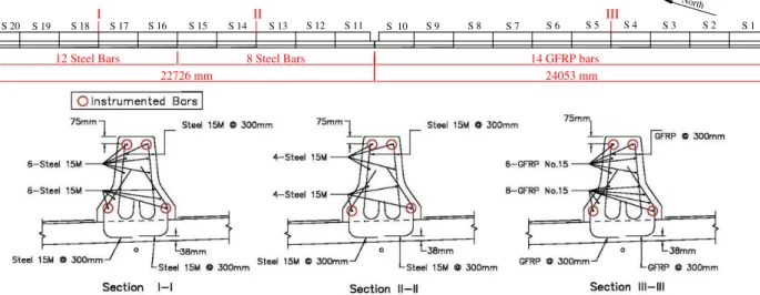
The MTQ is currently using two standard designs for the GFRP and steel-reinforced barriers of Type MTQ 202ME. Both of them have the same transverse reinforcement amount of GFRP or steel bars (15M@300 mm). However, the steel-reinforced barrier contains 8 steel bars (15M) as longitudinal reinforcement and the GFRP-reinforced barrier contains 14 GFRP bars (No. 15) as longitudinal reinforcement. As the longitudinal reinforcement plays the main role in controlling restrained shrinkage and consequently transverse cracking in the barrier walls, the MTQ aims at investigating the optimum design of the barrier wall and determining the horizontal
- 3 -
reinforcement amount that should be provided. This was planned to be achieved through the median barriers of the 410 overpass bridge on Hwy 410, Sherbrooke, Quebec. Two sections reinforced with GFRP and steel bars were considered in this investigation. The structural details and behaviour of this project can be found elsewhere (Claude et al. 2011). In order to monitor the behaviour of the median barrier, a multitude of sensors were selected to capture the strain and temperature variations of the barrier over time. A total of 98 sensors were attached to the reinforcing bars and embedded in concrete. The sensors include fibre optic sensors (FOS), vibrating wire strain gauges (VWSG), thermometers (TH-T) and electrical resistance strain gauges (ESG). The vibrating wire sensors were connected to one multiplexer and a datalogger type CR10X to capture their readings while the FOS sensors were connected to a 16-channel DMI unit to capture and store their readings. This paper presents the details of the instrumentations as well as their readings. Typical readings from the FOS, VWSG and ESG strains are also presented. The results are discussed and concluding remarks are presented.
2 DESCRIPTION OF THE BRIDGE BARRIERS
The median barrier considered in this investigation was part of the Hwy 410 overpass bridge going over Boulevard de l’Université in the municipality of Sherbrooke (Canada), and was built in June 2010. The six-lane bridge was built as part of the extension of Highway 410 in Sherbrooke. It was constructed using typical slab-on-girder structural system with a total length of about 47.0 m. The median barrier was of Type MTQ 202ME and was cast using a ready-mix high-performance concrete of Type MTQ XIII (50 MPa). Figure 1 shows the general layout of the bridge (plan view), and the cross-section geometry of the median barrier. In order to study the behaviour of different reinforcement type and rate the barrier has been divided into two principal sections. The first section (S1 to S10 in Figure 2) was reinforced with 14 longitudinal GFRP bars No. 15 designated according to CAN/CSA S807-10 (2010). The second section itself is divided into two sections reinforced with 15M galvanized steel bars. The first sub-section (S10 to S15 in Figure 2) was reinforced with a total of 8 steel bars 15M while the second one (S16 to S20 in Figure 2) was reinforced with a total of 12 steel bars 15M. Figure 2 shows the cross-sections of the median barrier as well as the locations of the longitudinal instrumented bars.
As an innovative solution to eliminate the corrosion of steel reinforcement and related concrete deteriorations, MTQ decided to use the non-corrodible glass fiber-reinforced polymer (GFRP) reinforcing bars as reinforcement for concrete barrier. Consequently, through a collaboration project with the University of Sherbrooke, this project was mandated to study shrinkage and cracking behavior of median barriers reinforced with GFRP and galvanized steel bars in order to evaluate the efficient amount of horizontal reinforcement that is necessary to keep the crack widths under control. Besides, it was also decided to employ a long-term monitoring technique to evaluate the performance of the GFRP-reinforced concrete barrier.
(a) (b)
Median Barrier
GFRP-Reinforced Section Steel Reinforced Sections
Supporting steel beams 46791 46767 46779 24053 22726 830
- 4 -
Figure 1. Layout of the project: (a) Hwy 410 overpass bridge; (b) Median barrier cross-section (Dimensions in mm)
Figure 2. Reinforcement details of the median barrier
3 INSTRUMENTATIONS
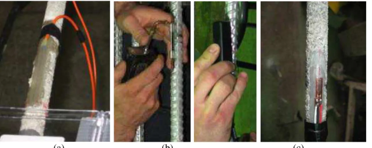
Since the main objective was to investigate and monitor the shrinkage and cracking behavior of the median barrier of Type MTQ 202ME, A set of sensors as well as appropriate readout units were selected to monitor the performance of the barrier (GFRP- and steel-reinforced sections). The instrumentations included a total of 15 fibre optic sensors (FOS) attached to the GFRP reinforcing bars; 20 vibrating wire strain gauges of type SM2 (VWSG) attached to the steel bars; 8 vibrating wire strain gauges of type EM5 (VWSG) embedded in the concrete; 4 thermometers (TH-T); and 51 electrical resistance strain gauges (ESG) attached to both GFRP and steel bars. Figure 2 shows the location of the instrumented bars while the locations of the different sensors that were attached to the top and the bottom reinforcing bars (steel and GFRP) are shown in Figure 3. Figures 4 and 5 show the different sensors after being installed. The FOS, VWSG, and ESG were attached to four longitudinal bars (2 bottom bars and 2 top bars) to capture the strain variation along the depth of the barrier. The vibrating wire strain gauges for concrete were installed in the concrete at the level of the instrumented longitudinal bars. The thermometers were installed close to these reinforcing bars to determine the actual temperature surrounding the bars for temperature corrections of the strain data.
14 GFRP bars 12 Steel Bars 8 Steel Bars
North S 1 S 2 S 3 S 4 S 5 S 6 S 7 S 8 S 9 S 10 S 12 S 13 S 14 S 15 S 16 S 17 S 18 S 19 S 20 S 11 22726 mm 24053 mm I II III
- 5 -
Figure 3. Instrumentation layout of the median barrier (plan view)
(a) (b) (c)
Figure 4. Instrumentation of the reinforcing bars: (a) Fiber optic sensors glued on GFRP bars; (b) VWSG (SM2) welded on steel bars; (c) ESG glued on steel and GFRP bars
- 6 -
(a) (b)
Figure 5. Instrumentation of the barrier: (a) VWSG (EM5) embedded in concrete; (b) Thermometers (TH-T) attached to the reinforcing bars
Three readout units were needed to collect the strain and temperature readings from the VWSG, FOS, TH-T and ESG. These units were Datalogger CR10X for the vibrating wire sensors as well as the TH-T sensors, DMI unit for the fiber optic sensors, and P-3500 readout unit for the electrical resistance strain gauges. The TH-T and VWSG sensors were connected and controlled by a Datalogger unit type CR10X (Figure 6a) while the FOS were connected through a 16-channel DMI unit (Figure 6d). To accommodate the number sensors that were installed, two multiplexers (Figure 6b; 6c) were installed and the VWSG and TH-T sensors were connected to it which, in turn, were connected to the Datalogger CR10X (Figure 6a). These units are installed at the North-West side of the bridge abutment. Thus, the reading from TH-T, VWSG and FOS were respectively store in the Datalogger and DMI units. For the moment, no phone line is installed in the units so the results must be taken periodically with portable PC. On the other hand, the ESG data are being collected manually by a P-3500 unit (Figure 6e). In addition to that, a crack mapping is done periodically through visual observation and measurement where the crack widths were measured using a hand-held microscope of 50X magnifying power. After connecting the FOS sensors to the DMI unit, the pre-prepared program was uploaded to the Dadalogger CR10X by connecting it to a computer and using the PC200W software (Campbell 2010). On the other hand, FISO Commander 2 Standard software (FISO 2010) was used to program the DMI unit. The readings of the Datalogger CR10X are being acquired using the PC200W software (Campbell 2010) while the readings of the DMI unit are being collected using FISO Commander 2 Standard software (FISO 2010).
- 7 -
(a) (b) (c)
(d) (e)
Figure 6. Readout units and multiplexers: (a) Datalogger CR10X; (b) Multiplexer-1; (c) Multiplexer -2; (d) DMI for FOS; (e) P-3500
4 MONITORING RESULTS
4.1 Temperature variation
The variation of the temperature inside the median barrier in the GFRP- and steel-reinforced section was captured using the four TH-T and two VWSG sensors starting from June 9, 2010. The measured temperature variation inside the barrier wall is presented in Figure 7. It can be noticed that the temperature range from -12 oC to 41 oC during the period of data taking. Also, in this figure, the effect of cement hydration heat can be clearly observed during the first day after casting (June 9, 2010), after that time the concrete temperature followed the ambient air temperature. Thus, the temperature variation is expected to follow the seasonal temperature changes.
Figure 7. Temperature variation in the median barrier
4.2 Strains in GFRP and steel bars
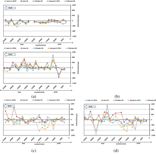
The strain variations in the reinforcing bars (GFRP and steel) were recorded using the FOS, VWSG, and ESG, and are presented in Figure 8. Therefore, the graphs in this figure show the deformations along the barrier length depending on the location of the sensors attached to the
- 8 -
four instrumented longitudinal bars. It should be noted that the strain values presented in these four figures were measured from June 2010 to February 2011.
It should be mentioned that the initial readings for FOS, VWSG, and ESG that were taken directly before casting on June 2009 were used as initial readings and were set to zero values. Thus, the reported strains include the induced strains from shrinkage of the concrete as well as the temperature variation.
The maximum measured tensile strain in the bottom reinforcement between June 2010 and February 2011was small in comparison to the top instrumented bars. This is attributed to the restraint from the bridge deck slab, which affects more the deformation at the bottom of the barrier than at the top.
(a) (b)
(c) (d)
Figure 8. Strain profile in the instrumented bars: (a) Bottom - East side; (b) Bottom - West side; (c) Top - East side; (d) Top - West side
4.3 Crack mapping and widths
As soon as the formwork was removed on June 16, 2010 (7 days after casting), the crack pattern and the initial crack widths in the GFRP- and steel-reinforced sections were recorded. The initial maximum crack width recorded in the steel-reinforced sections of the barrier (with either 8 or 12 bars) was 0.15 mm. The initial crack spacing ranged from 406 mm to 1434 mm with an average of 749 mm in the section reinforced with 8 steel bars 15M (S11-S16). However, in the
-1200 -800 -400 0 400 800 1200 D e fo rm a ti o n ( με) Location (mm)
June 11, 2010 June 16 October 26 January 6, 2011 February 28
Steel GFRP North -1200 -800 -400 0 400 800 1200 D e fo rm a ti o n ( με) Location (mm)
June 11, 2010 June 16 October 26 January 6, 2011 February 28
North GFRP Steel -1200 -800 -400 0 400 800 1200 D e fo rm a ti o n ( με) Location (mm)
June 11, 2010 June 16 October 26 January 6, 2011 February 28
Steel GFRP North -1200 -800 -400 0 400 800 1200 D e fo rm a ti o n ( με) Location (mm)
June 11, 2010 June 16 October 26 January 6, 2011 February 28
Steel GFRP
- 9 -
section reinforced with 12 steel bars 15M (S16-S20), the initial crack spacing ranged from 316 mm to 2195 mm with an average of 905 mm. The GFRP-reinforced section exhibited an initial maximum crack width of 0.18 mm, which is almost the same as that of the steel-reinforced section. The initial crack spacing ranged from 406 mm to 1166 mm with an average of 705 mm, which is also close to the average value measured in the steel-reinforced section. It should be noted that the sudden changes in the barrier geometry and reinforcement detail at the light pole between S10 and S11 resulted in the formation of two additional transverse cracks with larger widths (0.33 mm and 0.34 mm).
The time evolution of crack width is presented in Figure 9. The cracks in both of the GFRP- and steel-reinforced sections developed in the first month after removing the formwork. Since then, only one crack appeared in each of the two sections on October 28, 2010. However, the crack width in both reinforced sections has increased from June 16 to October 28, as clearly shown in Figure 9. Thereafter, the crack widths followed the seasonal temperature variation and have decreased with decreasing ambient temperature in the winter season.
Figure 9. Evolution of average crack width
5 CONCLUDING REMARKS
1- The instrumentation set for strain variation and temperature work well towards long-term monitoring and evaluating the structural performance of the GFRP- and steel-reinforced concrete bridge barriers.
2- The Datalogger (CR10X) and the DMI units are working well and they are capable of controlling the entire set of sensors installed in the barriers, except the ESG which are being measured using the P-3500.
3- The variations in the recorded longitudinal strains and in the measured crack widths were observed to follow the seasonal variation of temperature.
4- The long-term monitoring of the bridge barrier will enable a better understanding of the behaviour of the GFRP- and steel-reinforced barriers under real environmental conditions and the optimization of bridge barrier designs of Type MTQ 202ME.
6 ACKNOWLEDGMENTS
The authors would like to express their special thanks and gratitude to the Natural Science and Engineering Research Council of Canada (NSERC) and The Ministry of Transportation of Quebec (MTQ). The authors are grateful to the consulting engineering firm Teknika-HBA Inc. The authors would also like to thank the technical staff of the structural lab of the Dept. of Civil Eng. at the Univ. of Sherbrooke for their help with the bridge instrumentation in this project.
16/Jun/2010 16/Jul/2010 16/Aug/2010 15/Sep/2010 16/Oct/2010 15/Nov/2010 16/Dec/2010
0.00 0.05 0.10 0.15 0.20 0.25 0.30 0 50 100 150 200 Cr ack W id th (m m ) Time (Days) GFRP(S1-10) Steel (S11-15) Steel (S16-20) Total Reinforcements
- 10 -
7 REFERENCES
Campbell Scientific Inc. 2010. Datalogger support software : PC200W version 4.1 & LoggerNet version
3.4.1. North Logan, Utah, USA. (www.campbellsci.com).
Canadian Standards Association (CSA). 2010. Specification for fibre-reinforced polymers. CAN/CSA S807–10, Rexdale, Ontario, Canada, 27p.
Claude, J.-F, Ahmed, E, Cusson, D, and Benmokrane, B. 2011. Early-Age Cracking of Steel and GFRP-Reinforced Concrete Bridge Barriers. Proceedings of the 2nd International Engineering Mechanics and Materials Specialty Conference, CSCE, Ottawa, Ontario, June 14-17, CR-ROM, 10 p.