S P E C I A L I S S U E
Andreas J. Wirth · Thomas L. Mueller · Wim Vereecken · Cyril Flaig · Peter Arbenz · Ralph Müller ·
G. Harry van Lenthe
Mechanical competence of bone-implant systems can
accurately be determined by image-based micro-finite
element analyses
Received: 9 December 2008 / Accepted: 3 October 2009 / Published online: 29 October 2009 © Springer-Verlag 2009
Abstract The precise failure mechanisms of bone implants are still incompletely understood. Micro-computed tomography in combination with finite element analysis appears to be a potent methodology to determine the mechanical stability of bone-implant constructs. To assess this microstructural finite element (µFE) analysis approach, pull-out tests were designed and conducted on ten sheep vertebral bodies into which orthopedic screws were inserted.µFE models of the same bone-implant constructs were then built and solved, using a large-scale linear FE-solver.µFE calculated pull-out strength correlated highly with the experimentally mea-sured pull-out strength (r2= 0.87) thereby statistically supporting the µFE approach. These results suggest that bone-implant constructs can be analyzed usingµFE in a detailed and unprecedented way. This could potentially facilitate the development of future implant designs leading to novel and improved fracture fixation methods.
Keywords Bone-implant competence · Micro-finite element analysis (µFEA) · Bone microstructure · Peri-implant bone quality· Mechanical testing · Pull-out strength
1 Introduction
Osteoporosis is a bone disease characterized by a reduction in bone mineral density (BMD) and structural deterioration of bone tissue, leading to an increased risk of fracture. According to the National Osteoporosis Foundation in the United States, 10 million U.S. citizens (of which 8 million are women) already have the A. J. Wirth and T. L. Mueller contributed equally to this work.
This research was funded by the AO Foundation (network grant CPP1). Computational time was granted by the Swiss National Supercomputing Centre (CSCS).
A. J. Wirth· T. L. Mueller · W. Vereecken · R. Müller · G. H. van Lenthe (
B
)Institute for Biomechanics, ETH Zurich, HPI F 22, Wolfgang-Pauli-Strasse 14, 8093 Zurich, Switzerland E-mail: [email protected] URL: http://www.biomech.ethz.ch/ Tel.: +41-44-632-4591 Fax: +41-44-633-1573 T. L. Mueller E-mail: [email protected] C. Flaig· P. Arbenz
Chair of Computational Science, ETH Zurich, Zurich, Switzerland E-mail: [email protected]
W. Vereecken· G. H. van Lenthe
disease and almost 34 million more are estimated to be at risk for osteoporosis [1]. The estimation is that half of the women and a quarter of men aged 50 years or older will suffer an osteoporosis related fracture within their lifetime [2]. Due to the rapidly ageing American population, the annual direct costs of osteoporosis in the US are projected to reach $25.3 billion by 2025 and even $50 billion by 2040. This phenomenon can be directly transferred to most developed countries [3,4]. About 2 million osteoporosis-related fractures occur every year in the US in men and women aged 50 or older of which just fewer than 300,000 are hip fractures and almost 550,000 are vertebral fractures [2].
The fact, that osteoporosis leads to fractures, is known. In contrast, the assumption that osteoporosis com-plicates the treatment of these fractures is rather not [5], and it has not been in the focus of treatment planning up to now. For a long time orthopedic implants were developed for patients with a good bone stock. The funda-mental that bone mechanical properties depend on density and structure was not really considered. Therefore, it is not surprising that implants developed for good bone quality fail in osteoporotic bone [6,7]. Furthermore, recent studies are becoming available that show a correlation between the rate of implant failure and local bone quality [8–11]. From engineering principles it can be expected that implant stability depends on implant fixation, on the amount and quality of peri-implant bone and on how that bone deforms and eventually fails during implant loading. It would equally depend on the size, location, and quality of the local bone-implant contact areas. Indeed, experiments have shown that prototypes specifically designed for severely osteoporotic bone survive significantly longer during cyclic testing than comparable conventional implants [12]. However, a detailed understanding of the mechanisms underlying implant anchorage and stability is lacking and it is not clear to what extent size, location, and quality of the local bone-implant contact areas play a role in the pro-cesses of local damage and final implant failure. In order to develop better implants, a thorough understanding of factors leading to failure as well as the knowledge how to influence them is needed.
Not all these failure mechanisms can be investigated by experimental measurements, e.g. no methods exist to measure the forces acting on a screw in vivo, nor do sophisticated osteoporotic animal models exist that could allow testing orthopedic screws in low-quality bone. Furthermore, access to osteoporotic human bone is generally very limited, which limits the use of standardized tests and hinders doing proper statistics. Therefore computer simulations, finite element (FE) models in particular, have great potential to establish as an alternative for experimental biomechanical tests on bone-screw structures. FE analyses of bone-implant constructs have addressed phenomena at the apparent level, such as overall structural competence [13,14], as to get a better understanding of load distributions when using different kinds of implant configurations. Other FE models addressed the effects of screw design, and analyzed overall geometries, thread profiles and surfaces [15,16]. Whereas in all these models bone’s macroarchitecture could be handled relatively easily, its material properties, which are tightly linked to bone’s microarchitecture [17], are more difficult to model. Hence, nearly all studies have simplified cortical and trabecular bone to homogeneous and isotropic linear elastic materials. Although such simplifications may be justified for the determination of non-local phenomena [14], the application of averaged bone properties for local analysis in highly heterogeneous and anisotropic cancellous bone may not be reasonable; instead, it seems appropriate that for cases like this the discrete nature of trabecular bone has to be taken into account. At present, only very few publications exist that do not model trabecular bone as a continuum in the bone-implant constructs [18].
Finite element analyses based on micro-computed tomography (µCT) images of bone-implant constructs appear to be promising to further enhance our knowledge of the local stresses, strains, and deformation behav-ior of the bone in the vicinity of the implant. µCT has become the method of choice in quantifying 3D bone microstructure. Microarchitectural bone imaging is a nondestructive, noninvasive, and precise procedure with which both the apparent density and the trabecular microstructure of intact bones and bone samples can be assessed in a single measurement. It provides the necessary detail to accurately represent the complex microstructure of trabecular bone. DesktopµCT is a precise and validated technique [19–21], and has been used extensively to study bone microarchitecture [21–24], demonstrating that trabecular bone can have very distinct microarchitectures that are remarkably heterogeneous throughout the skeleton [25–27]. Direct voxel-to-element conversion is an easy and straight-forward approach to generate micro-structural finite element (µFE) models. Furthermore, this method is fast and can be completely automated. It can provide insight into the load transfer through the bone architecture and help to understand how differences in bone microarchitec-ture influence bone strength. These models are necessarily large to capmicroarchitec-ture the microstructural details of the bone, and require special solution schemes. Within the last few yearsµFE analysis has become a well-estab-lished technique for analyzing the mechanical quality of bone samples [28]. For linear deformation conditions, comparison between biomechanical compression tests on excised trabecular bone samples andµFE show very good agreement (r2 = 0.92) when a homogeneous, isotropic tissue modulus is applied [29,30]; this seems
to hold true for normal as well as osteoporotic bone [31]. As well, it has been shown that at the apparent level, theseµFE models can accurately predict trabecular bone failure for bovine [32] as well as for human trabecular bone [33]; theµFE-predicted apparent stresses and strains at failure were equal to experimentally measured values for the same bone specimens. Nevertheless the material properties for bone at the tissue level as determined by µFE differ in some cases from those determined by other experimental techniques; systemic experimental differences such as the scale of the tests and specimen preparation can explain these differences [34].
The steady increase in computational power over the last years, using parallel processors in supercomputers, has made it possible to analyze intact human bones, or large portions thereof [35–37]. A recent implementation even allowed to solve a model with nearly 1.5 billion degrees of freedom within 30 minutes, to simultaneously increase the level of detail and the size of the analyzed bone volume (BV) [38,39]. With that,µFE analyses have reached a level where relatively large objects can be analyzed in great detail, opening up for the first time a detailed analysis of implant behavior in trabecular bone. However, whether theseµFE models would provide accurate results for bone-implant constructs is not known, because first, bone and implant form two different entities, and second, they have largely differing material properties. Therefore, the aim of this study was to assess such models by relating computational findings to experimental biomechanical data on bone-implant constructs.
2 Methods
Four sheep spines, from a study unrelated to the present one, were provided by the slaughterhouse of the Vetsuisse Faculty at the University of Zurich and had been stored in a freezer at a temperature of−21◦C. All five sheep were female between 1 and 2 years old. Prior to dissection of individual vertebrae, the spines were thawed, and refrozen immediately after. In total, twelve vertebrae from the thoracic region (T1–T3) were harvested. Two of them were used in a pilot study, leaving ten specimens for this study.
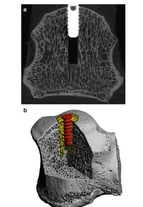
Commonly used dental screws were implanted. The screws had an outer thread diameter of 3.3 mm and a thread height of 10 mm (Fig.1). The screws were inserted in the upper surface of the vertebral body which was fixed in a clamp. Screw insertion was performed according to the manufacturer’s instructions. First, a receiving channel of 2.2 mm was drilled at 800 rpm to a depth of 18 mm after which a drill of 2.8 mm at 500 rpm enlarged this channel. After the creation of this pilot hole the screws were placed in the specimen using a torque-controlled screwdriver, according to the ASTM standard F 543. Insertion depth was 10 mm, corre-sponding to the thread height. To minimize inter-specimen variability, the time between thawing the samples and the insertion of the screws was standardized to 5 h. After screw insertion, all samples were frozen again at a temperature of−21◦C and stored for further processing.
2.1 Experimental testing
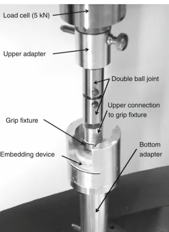
To prevent shear stresses and bending effects during screw extraction, care was taken to align the specimens properly in the mechanical testing device. For that purpose, a polymer part was placed on top of the screw’s grip fixture such that the screws were aligned vertically. With the polymer part still in place, each vertebra was put at the bottom of a special-purpose aluminum part (Fig.2). To fixate the sample, a mixture of meth-ylmethacrylate powder (MMA) and a liquid catalyst was used (Technovit 3040, Heraeus Kulzer GmbH), a polymer resin generally used for indirect surface testing. By mixing these two substances in a ratio of two to one, fluid PMMA was created which hardened after 15 min. This fluid was poured in the aluminum part in which the vertebra was resting. The part in which the embedding took place was subsequently connected by threaded holes to a custom-made aluminum adapter, fitting around the bottom platen of a universal mechanical testing machine (5 kN Allround-Line, Zwick GmbH, Ulm, Germany). To correct minor deflections in axial alignment, a double ball joint was used, connecting to the upper platen of the testing bench where the load cell was located.
At the start of the pull-out test the crosshead of the testing bench moved at a rate of 2.5 mm/ min until a pre-load of 10 N was reached, defined as the starting point of the test. Subsequently, the crosshead’s displacement rate was set to 5 mm/ min, according to the ASTM standard F 543. The test ended when the measured force had dropped to 80% of the maximally measured force. The displacement of the crosshead, as well as the force acting on the load cell, was recorded. Pull-out strength was defined as the maximum force measured in the experiment. Ultimate displacement was defined as the displacement reached at maximum force. In accordance
Fig. 1 aµCT grayscale image showing the thin trabecular bone structures, the drill canal, the implant as well as the implant bone interaction. The outer thread diameter of the implant is 3.3 mm. b Segmented 3D representation of the inserted screw into the sheep vertebra. Bone microstructure is still nicely visible, even though resolution of the image was lowered by a factor of three in each direction. One VOI with an outer radius of 3 mm is indicated
with the current methodology to quantify the stiffness of a bone sample, the stiffness of the bone-implant construct was defined as the slope of the force–displacement curve between 30 and 70% of pull-out strength.
2.2µCT scanning and analysis
Before embedding in the aluminum holders, each sample was imaged with a micro-computed tomography systemµCT 80 (Scanco Medical, Brüttisellen, Switzerland) using a 25µm nominal resolution to assess the trabecular bone architecture and screw geometry (Fig.1a). The samples had been taken out of the freezer and stored in a fridge at 4◦C for 22 h in a saline soaked towel. The bone-implant constructs were placed in a grip fixture, which itself fitted into a custom-made polymer part, used to align the screw exactly in the center of the µCT sample holders. Proper alignment was crucial to reduce imaging artifacts which would have hampered
Load cell (5 kN)
Upper adapter
Double ball joint
Upper connection to grip fixture Grip fixture
Bottom
Embedding device adapter
Fig. 2 Setup of the mechanical testing apparatus. The load cell is the connection to the upper part, the bottom adapter the connection to the lower part of the commercially available ZWICK testing device
further image processing and analyses. While being submersed in saline, the entire vertebrae with implanted screws were scanned with the screw axis coinciding with the sample rotation axis.
The reconstructed images were filtered using a constrained three-dimensional Gaussian filter to partially suppress noise in the volumes (σ = 1.2 and support = 1), and segmented using global thresholds to obtain representations of bone, implant and PMMA (Fig.1b). During segmentation, several image corrections were applied to reduce imaging artifacts [40].
Analyses for bone volume fraction (BV/TV) were performed in cylindrically shaped volumes of interest (VOI) around the screws. The long axes of the VOIs were aligned with the center line of the screws. In order to reduce the influences ofµCT measurement artifacts, the volume between the screw threads was neglected. The height of the VOIs was taken constant at 13 mm, hence, 3 mm higher than the screw’s length (Fig.1b). This was motivated by the stress and strain distributions seen in microstructural FE analysis of two pilot tests. The radius of the cylindrical regions was varied between the radius of the outer thread (1.65 mm) and 6.0 mm.
2.3 Microstructural FE analysis
TheµFE meshes consisted of cubic hexagonal elements. A custom in-house mesher was used to generate the FE mesh of each sample directly from theµCT data, employing a direct voxel-to-element approach. Mesh-ing was performed on 8 dual-core 2.6 GHz AMD Opteron processors of a Cray XT3 system of the Swiss National Supercomputing Centre (CSCS, Manno, Switzerland). To reduce computational costs, theµCT data was downscaled by a factor of three in all directions prior to meshing.
A common approach forµFE analyses is to consider bone to be homogeneous at the tissue level; thus, the same isotropic Young’s modulus is given to every element. In comparison studies it could be shown that there is a high degree of agreement betweenµFE analyses and experimental test [30,41], even though diverse values for Young’s modulus have been found. This could be explained by differences in experimental setup, as well as the finesse of the mesh. Furthermore, the influence of material anisotropy at the bone tissue level
Number of elements highly strained volume 0 0 5 0 7 Effective strain [%] 0 0.5 0.7
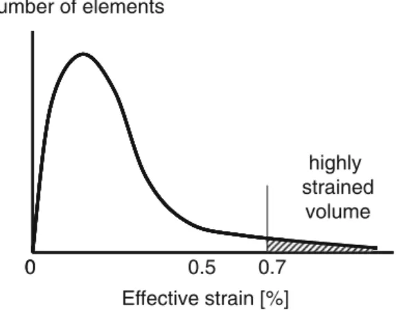
Fig. 3 Biomechanical measurements suggested that failure seems to occur as soon as the effective strain levels in a characteristic fraction of the bone volume exceed a critical threshold of 0.7%. The force, resulting from the applied 1% displacement is scaled, such that a certain volume (highly stressed volume) of all elements in distal radius have effective strain values above 0.7% strain (after Pistoia et al. [43])
seems to be negligible as such good agreement was found not only in the main material direction, but also in perpendicular directions, which indicates that the anisotropic behavior of trabecular bone is mainly governed by the orientation of the trabeculae. Therefore, linear and isotropic material behavior was assumed for all materials used in the present study. Young’s moduli were defined at 5, 114 and 2 GPa for bone, implant and PMMA, respectively; the Poisson ratios were set to 0.30, 0.34 and 0.36, respectively. Material properties of the titanium implant and the PMMA were defined based on the information from the manufacturers, whereas bone mechanical properties were based on reported values [30,41]. Boundary conditions that represented the biomechanical tests were defined. Hence, a displacement of 1% of the overall height of the models was applied to the outer end of the screw, while all nodes on the bottom of the models were restrained in direction of the loading only, except for two other nodes which were restricted in additional directions in order to prevent rotation and translations. The rest of the boundary is free. The interface between implant, bone and embedding material were modeled as full contacts, resulting in a model consisting of only one body with different material properties that represented the different components. For the solution of these models a fully parallel materially and geometrically linear custom finite element package ParFE, which works with a multilevel preconditioner, was used [38,42]. The models were processed on a Cray XT3 system on 720 dual-core 2.6 AMD Opteron processors with 1.4 TB of main memory. Post-processing was done using in-house code. Visualizations were created in parallel using open source program ParaView (http://www.paraview.org/) on 4 AMD Opteron CPU nodes with a total of 32 GB of memory on an HP-XC cluster.
Stiffness was determined by dividing the calculated reaction force by the prescribed displacement. Strength was estimated based on a structural hypothesis as developed forµFE models of human distal forearms [43]. According to this concept, failure is expected to occur as soon as the effective strain levels in a characteristic fraction of the BV exceed a certain critical threshold. In the original formulation the characteristic BV fraction was set to 2% and the effective strain threshold was set to 0.7% (Fig.3). Because it is questionable whether the exact same characteristic values are also applicable to bone-implant constructs and because of improved image resolution we set up an automated procedure to cover all combinations of the size of the VOI and the critical BV fraction. Specifically, the effective strain was calculated for all bone elements in the VOI that were defined for theµCT analyses. The calculated external forces on the µFE models were then scaled such that a specific element fraction exceeded a general effective strain threshold. This was done for all possible element fractions. Such scaling was possible because theµFEA were fully linear. To determine optimal VOI and critical BV, linear correlations were performed between FE-calculated pullout strength and mechanically measured pullout strength
2.4 Statistical analysis
It was our aim to determine how well stiffness and strength of bone-implant constructs can be determined from µFE models. To quantify that, the coefficient of determination (r2) based on the Pearson product-moment
cor-relation coefficient was used. All statistical analyses were performed with Excel 2003 (Microsoft, Redmond, USA).
3 Results
3.1 Experimental testing
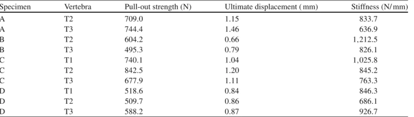
All experimental tests were performed successfully, and resulted in similar force–displacement curves (Fig.4). Pull-out stiffness was determined from the linear portion of the force–displacement curves in order to omit inelastic effects related to alignment of the experimental setup at the beginning of the experiment as well as plastic deformation prior to failure. Pull-out forces ranged from 495 up to 842 N, ultimate displacements from 0.66 to 1.46 mm and stiffness from 637 to 1,212 N/ mm, respectively (Table 1). The average pull-out force for all ten specimens was 643± 118 N. All samples were treated as independent, because statistical analyses showed no relationships between vertebrae from the same sheep, nor between vertebrae at the same level from different sheep. A relatively good correlation between the pull-out force and the ultimate displacement (r2= 0.58) was found. Stiffness did not correlate to pull-out strength (r2= 0.0001).
Fig. 4 Force–displacement curves for all ten mechanical pull-out tests. Data recording started always at an initial pre-load of 10 N. Pull-out strength was taken as the peak after which the measured force dropped by at least 20%. In order to determine stiffness, only the linear part of the curves were evaluated
Table 1 Experimental results from the ten specimens tested
Specimen Vertebra Pull-out strength (N) Ultimate displacement ( mm) Stiffness (N/ mm)
A T2 709.0 1.15 833.7 A T3 744.4 1.46 636.9 B T2 604.2 0.66 1,212.5 B T3 495.3 0.79 826.1 C T1 740.1 1.04 1,025.8 C T2 842.5 1.20 845.2 C T3 677.9 1.11 763.3 D T1 518.6 0.84 846.3 D T2 509.7 0.86 686.1 D T3 588.2 0.87 926.7
3.2 Microstructural FE analysis
All tenµFE models were successfully created and analyzed. The meshing procedure took 536 s for all models together. The number of elements in the models ranged from 12.1 to 17.9 million; the degrees of freedom from 50.7 to 87.2 million. The time needed to solve the models ranged from 115 to 200 s; overall processing wall clock times were in between 134 and 270 s.
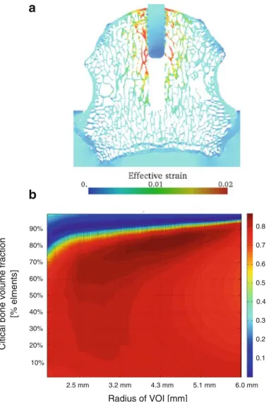
A visual representation of the effective strain distribution of one representative specimen is given in Fig.5a. The strain distribution is relatively homogenous as no clear differences in opposite bone regions around the implant can be seen.
Computationally analyzed stiffness ranged from 3,138 to 11,043 N/ mm, with an average stiffness and standard deviation of all ten specimens of 7,419 ± 2,420 N/ mm. Thus, the computational results are close to a factor of 9 times higher than the measured stiffness. Furthermore, measured andµFE-derived stiffness did not correlate (r2= 0.002).
On the other hand, the pull-out forces showed high correlations. The FE-calculated pull-out strength depended on the size of the VOI (radius of VOI) and on the amount of highly stressed volume. To determine optimal parameters, linear correlations were performed between FE-calculated pull-out strength and mechan-ically measured pull-out strength (Fig.5b). Best correlation (r2= 0.87) was found when taking a VOI with a
a
b
90% 0.8 50% 60% 70% 80% 0.5 0.6 0.7 [% elmen ts] 20% 10% 30% 40% 0.1 0.2 0.3 0.4Citical bone volume fraction
Radius of VOI [mm]
2.5 mm 3.2 mm 4.3 mm 5.1 mm 6.0 mm
Fig. 5 a Strain distribution (effective strain) of one typical specimen. Highest strains can be found at the bone microarchitecture close to the implant. b Parameter study investigating the correlation between measured and estimated pull-out strength. Critical bone volume fraction and the radius of the VOI were varied
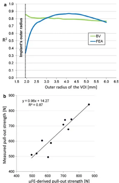
Fig. 6 a Pull-out strength prediction based on FEA and BV depends on the volume of interest, represented here by the radius of the VOI. b Best prediction of measured pull-out strength was achieved for the pull-out strength as estimated by the FEA resulting in an r2of 0.87. Critical volume fraction was taken at 80%. The tissue effective strain threshold was set to 0.25%
radius of 4.7 mm in combination with a highly stressed BV fraction of 84%. It should be noted that the obtained correlations were relatively insensitive to the specific parameter values (Fig.5b).
Bone volume was a good predictor of measured pull-out strength as well. Best linear correlation between measured pull-out strength and BV was achieved when taking a VOI with a radius of 1.94 mm (r2 = 0.86). Correlation coefficients for two indices, BV and FE-derived pull-out strength, are depicted in Fig.6a where they were determined as a function of the size of the VOI. Finally, Fig.6b shows the single specimen’s corre-lation between the estimated and the measured pull-out force, demonstrating a very strong agreement between the two.
4 Discussion
In this study we assessedµFE analysis as a technique to determine the pull-out strength of bone screws. High correlations were found between pull-out strength as estimated fromµFE and the experimentally measured pull-out strength. This indicates thatµFE analyses can be used as a tool for the assessment of stability and strength of bone-implant constructs. Such a system could be used for the evaluation of newly developed implant designs prior to animal testing, hence, could save costs and time. The development of new implant designs
could potentially be accelerated and improved. It could prove especially beneficial in the design process of implants for low quality osteoporotic bone, because that type of bone deviates most from the currently assumed homogeneous bone properties.
Good correlations were found between the BV surrounding the implant and the measured pull-out strength. BV predicted strength best when the VOI was small (Fig.6a). The relatively high correlation of BV and mea-sured failure load in a small VOI close to the implant seems to indicate that the bone in close contact with the screw is important in providing good anchoring of the screw. However, it has to be realized that correlations were highest for small VOI. The outer radius of the smallest VOI was 1.94 mm such that the wall thickness of the hollow cylinder is only 0.29 mm. Potentially, this could lead to imprecise and deviating results in subsequent studies as the analyzed region is only of the thickness of one trabecula. Even higher correlations (r2= 0.87) were obtained whenµFE analyses were used to estimate pull-out strength. These results support the assump-tion that the estimated failure forces as well as the analyzed surrounding BVs are both good parameters to predict the measured failure force of a bone-implant construct.
A limitation of the study is that artifacts in the acquiredµCT images could influence the µFE results. In order to study this artifact related behavior, the solution would be to scan samples without an inserted screw. Afterwards the screw would have to be digitally added to the FE-model in order to compare these results with the ‘conventional’ method. Especially in the case of self-tapping screws this could be very interesting, since the bone debris, taken along with the screw on its way down, could be excluded possibly yielding better results. Since we used a strictly linear solver, friction forces cannot be modeled and taken into account in theµFE. This holds for the interface between PMMA and bone as well as for the one between bone and implant. We obtained a good predictive value forµFE-based strength which seems to suggest that the frictional forces are relatively small, and that load transfer between bone and implant is mainly through interconnections of bone trabeculae and the screw thread. A study using screws with larger threads and diameters could provide more in-depth information into the extent of these frictional forces.
WhereµFE-predicted pull-out strength correlated well to experimentally measured strength, µFE-pre-dicted stiffness did not show the same high correlation to experimentally measured stiffness. Several potential sources for this behavior were identified. First, the embedding of the vertebrae turned out to be insufficient. Although we took great care to embed them properly, and to have an accurate screw alignment, the PMMA slipped slightly within the aluminum holders, thereby decreasing the measured stiffness. Such slipping most probably has not affected all samples to the same extent. Second, it is unknown whether there has been some slipping between the screw and the surrounding bone before failure, which would have increased the compli-ance. Third, potential lack in the experimental system, such as in the double ball joint, would have reduced measured stiffness further. These effects could not be simulated in the µFE analyses. Fourth, we assumed identical bone tissue level properties for all vertebrae, whereas the actual material properties may have varied from vertebra to vertebra. And fifth, we used 5 GPa for bone tissue based on studies where bone tissue modulus was backcalculated fromµFE and experimental testing [30,41], but higher tissue moduli have been reported in the literature, especially when using measurements techniques that identified tissue properties on a smaller length scale. The inclusion of a deloading step during the experimental tests would potentially have allowed a more accurate determination of the elastic behavior of the surrounding bone [44]. It has to be noted though, that the test protocol as defined by ASTM 543 did not include deloading of the screw during the biomechan-ical measurement. Future studies using deloading may help to quantify the inelastic mechanisms involved in implant failure. And although the use of different tissue moduli would have changed the absolute values for bone-implant stiffness, we do not expect that the it would have had a significant influence on the correlation between experimentally determined stiffness and stiffness as derived fromµFEA.
In implant fixation a distinction can be made in the stability directly after implantation (primary implant stability) and the situation after several months when bone could potentially have grown onto the screw and establish a firm connection between implant and screw (secondary implant stability). Our experimental set-up clearly considers primary stability whereas our computational model could reflect the secondary stability because micromotion was not included in theµFE analyses. Nevertheless, even when assuming fully bonded contact areas between implant and bone we achieved a strong correlation. This likely indicates that frictional forces only play a minor role in primary implant stability, and that stability is achieved through form-locking of the threads into the bone.
Sheep vertebrae have been widely used as a model for human vertebrae for in vivo [45] as well as for in vitro [46] experiments. A morphological study showed that similarities between sheep and human vertebrae are strongest in the thoracic and lumbar regions and suggests sheep spines as a good model for the investigation of spinal implants [47].
Specimens tested in this study displayed a high BV density, not comparable to low density osteoporotic bone. For these specimens the calculated stresses close to the implant were relatively homogenously distrib-uted along the structure. It is expected that larger differences in stress distribution will occur when testing low density osteoporotic bones. Furthermore, we hypothesize that in these cases BV alone would no longer predict implant failure sufficiently well whereasµFE could still do as this analysis incorporates not only density but also structural information. These aspects need further experimental validation.
We inserted the screws in the proximal surface of the sheep vertebrae. This is not a physiological location; typically in spinal surgery, screws are implanted in the pedicles or the lateral mass. For this project, however, simulating a realistic clinical condition was not the main purpose. Instead we aimed for a set-up that would be reproducible. We selected the proximal surface because this allowed us to use the distal surface support during embedding of the vertebrae, which eased a proper alignment of the screws. Furthermore, the rather oriented trabecular structure as seen in humans is less pronounced in sheep which was visible onµCT images obtained in the preliminary study; hence, we expect that in sheep implant stability will be similar for axially and laterally placed screws.
There is no established computational technique to determine the pull-out strength for screws in trabec-ular bone. Furthermore, currently noµFE solver is available that includes conventional fracture mechanics. For that purpose, we adapted a method originally described by Pistoia et al. [43] to estimate strength from a linear-elastic analysis. Specifically, we varied two parameters to determine which combination would provide best estimates of pull-out strength. Best correlation was found when taking a VOI with a radius of 4.7 mm in combination with a highly stressed BV fraction of 84%. The critical volume of 84% is much higher than the 2% as in the original formulation. That, however, is to be expected, since we determined this percentage in a relatively small VOI just around the screw, hence, in a volume that is highly stressed and where failure initiation will occur; in contrast the 2% came from analyses where all bone was included. It is noteworthy that a relatively large range in parameters provided good strength estimates (Fig.5b). Based on our analyses we would recommend using a VOI with a wall thickness of about 2–4 mm, resulting in outer radii between 3.65 and 5.65 mm when considering the outer implant thread radius of 1.65 mm. In this volume around the implant stresses and strains are considerably higher than further away from the screw. Interestingly, µFE analyses predict measured pull-out strength better than BV alone for these representatively large VOIs, indicating that µFE analyses also include relevant aspects of bone architecture.
In summary, we successfully usedµFE analysis as a computational technique to determine the pull-out strength of bone screws. By using µFE analysis it has become feasible to analyze the effect of individual trabeculae and its contribution to implant stability and pull-out strength. Hence,µFE analyses may lead to a mechanistic understanding of why low density bone offers less potential for screw fixation than normal bone, and may aid to systematically develop more appropriate screws to treat osteoporotic fractures. We expect this to speed up the implant design process, because in the initial phases the amount of complicated and time consuming mechanical testing may be reduced through use ofµFE studies.
References
1. NOF 2002 America’s bone health: The state of osteoporosis and low bone mass in our nation
2. Chrischilles, E.A., Butler, C.D., Davis, C.S., Wallace, R.B.: A model of lifetime osteoporosis impact. Arch. Int. Med. 151(10), 2026–2032 (1991)
3. Burge, R., Dawson-Hughes, B., Solomon, D.H., Wong, J.B., King, A., Tosteson, A.: Incidence and economic burden of osteoporosis-related fractures in the United States, 2005–2025. J. Bone Miner. Res. 22(3), 465–475 (2007)
4. Ray, N.F., Chan, J.K., Thamer, M., Melton, L.J.: 3rd 1997 Medical expenditures for the treatment of osteoporotic fractures in the United States in 1995: report from the National Osteoporosis Foundation. J. Bone Miner. Res. 12(1), 24–35 5. Schneider, E., Goldhahn, J., Burckhardt, P.: The challenge: fracture treatment in osteoporotic bone. Osteoporos. Int. 16
(Suppl 2), S1–S2 (2005)
6. Cornell, C.N.: Internal fracture fixation in patients with osteoporosis. J. Am. Acad. Orthop. Surg. 11(2), 109–119 (2003) 7. Seebeck, J., Goldhahn, J., Morlock, M.M., Schneider, E.: Mechanical behavior of screws in normal and osteoporotic
bone. Osteoporos. Int. 16(Suppl 2), S107–S111 (2005)
8. Alsaadi, G., Quirynen, M., Komarek, A., van Steenberghe, D.: Impact of local and systemic factors on the incidence of oral implant failures, up to abutment connection. J. Clin. Periodontol. 34(7), 610–617 (2007)
9. Becker, W., Hujoel, P.P., Becker, B.E., Willingham, H.: Osteoporosis and implant failure: an exploratory case-control study. J. Periodontol. 71(4), 625–631 (2000)
10. Blomqvist, J.E., Alberius, P., Isaksson, S., Linde, A., Hansson, B.G.: Factors in implant integration failure after bone grafting: an osteometric and endocrinologic matched analysis. Int. J. Oral Maxillofac. Surg. 25(1), 63–68 (1996)
11. Bonnaire, F., Zenker, H., Lill, C., Weber, A.T., Linke, B.: Treatment strategies for proximal femur fractures in osteoporotic patients. Osteoporos. Int. 16(Suppl 2), S93–S102 (2005)
12. Goldhahn, J., Seebeck, J., Frei, R., Frenz, B., Antoniadis, I., Schneider, E.: New implant designs for fracture fixation in osteoporotic bone. Osteoporos. Int. 16(Suppl 2), S112–S119 (2005)
13. Lovald, S.T., Khraishi, T., Wagner, J., Baack, B., Kelly, J., Wood, J.: Comparison of plate-screw systems used in mandibular fracture reduction: finite element analysis. J. Biomech. Eng. 128(5), 654–662 (2006)
14. Cegonino, J., Garcia Aznar, J.M., Doblare, M., Palanca, D., Seral, B., Seral, F.: A comparative analysis of different treatments for distal femur fractures using the finite element method. Comput. Methods Biomech. Biomed. Eng. 7(5), 245–256 (2004) 15. Hansson, S., Werke, M.: The implant thread as a retention element in cortical bone: the effect of thread size and thread
profile: a finite element study. J. Biomech. 36(9), 1247–1258 (2003)
16. Huang, H.L., Hsu, J.T., Fuh, L.J., Tu, M.G., Ko, C.C., Shen, Y.W.: Bone stress and interfacial sliding analysis of implant designs on an immediately loaded maxillary implant: a non-linear finite element study. J. Dent. 36(6), 409–417 (2008) 17. Keaveny, T.M., Morgan, E.F., Niebur, G.L., Yeh, O.C.: Biomechanics of trabecular bone. Annu. Rev. Biomed. Eng. 3, 307–
333 (2001)
18. Tsubota, K., Adachi, T., Tomita, Y.: Effects of a fixation screw on trabecular structural changes in a vertebral body predicted by remodeling simulation. Ann. Biomed. Eng. 31(6), 733–740 (2003)
19. Müller, R., Hildebrand, T., Häuselmann, H.J., Rüegsegger, P.: In vivo reproducibility of three-dimensional structural prop-erties of noninvasive bone biopsies using 3D-pQCT. J. Bone Miner. Res. 11(11), 1745–1750 (1996)
20. Balto, K., Müller, R., Carrington, D.C., Dobeck, J., Stashenko, P.: Quantification of periapical bone destruction in mice by micro-computed tomography. J. Dent. Res. 79(1), 35–40 (2000)
21. Yamashita, T., Nabeshima, Y., Noda, M.: High-resolution micro-computed tomography analyses of the abnormal trabecular bone structures in klotho gene mutant mice. J. Endocrinol. 164(2), 239–245 (2000)
22. Turner, C.H., Hsieh, Y.F., Müller, R., Bouxsein, M.L., Baylink, D.J., Rosen, C.J., Grynpas, M.D., Donahue, L.R., Beamer, W.G.: Genetic regulation of cortical and trabecular bone strength and microstructure in inbred strains of mice. J. Bone Miner. Res. 15(6), 1126–1131 (2000)
23. Alexander, J.M., Bab, I., Fish, S., Müller, R., Uchiyama, T., Gronowicz, G., Nahounou, M., Zhao, Q., White, D.W., Chorev, M., Gazit, D., Rosenblatt, M.: Human parathyroid hormone 1-34 reverses bone loss in ovariectomized mice. J. Bone Miner. Res. 16(9), 1665–1673 (2001)
24. Dempster, D.W., Cosman, F., Kurland, E.S., Zhou, H., Nieves, J., Woelfert, L., Shane, E., Plavetic, K., Müller, R., Bilezikian, J., Lindsay, R.: Effects of daily treatment with parathyroid hormone on bone microarchitecture and turnover in patients with osteoporosis: a paired biopsy study. J. Bone Miner. Res. 16(10), 1846–1853 (2001)
25. Amling, M., Herden, S., Posl, M., Hahn, M., Ritzel, H., Delling, G.: Heterogeneity of the skeleton: comparison of the tra-becular microarchitecture of the spine, the iliac crest, the femur, and the calcaneus. J. Bone Miner. Res. 11(1), 36–45 (1996) 26. Hildebrand, T., Laib, A., Müller, R., Dequeker, J., Rüegsegger, P.: Direct three-dimensional morphometric analysis of human cancellous bone: microstructural data from spine, femur, iliac crest, and calcaneus. J. Bone Miner. Res. 14(7), 1167–1174 (1999)
27. Eckstein, F., Matsuura, M., Kuhn, V., Priemel, M., Muller, R., Link, T.M., Lochmuller, E.M.: Sex differences of human trabecular bone microstructure in aging are site-dependent. J. Bone Miner. Res. 22(6), 817–824 (2007)
28. van Rietbergen, B., Weinans, H., Huiskes, R., Odgaard, A.: A new method to determine trabecular bone elastic properties and loading using micromechanical finite-element models. J. Biomech. 28(1), 69–81 (1995)
29. Ladd, A.J., Kinney, J.H., Haupt, D.L., Goldstein, S.A.: Finite-element modeling of trabecular bone: comparison with mechanical testing and determination of tissue modulus. J. Orthop. Res. 16(5), 622–628 (1998)
30. Kabel, J., van Rietbergen, B., Dalstra, M., Odgaard, A., Huiskes, R.: The role of an effective isotropic tissue modulus in the elastic properties of cancellous bone. J. Biomech. 32(7), 673–680 (1999)
31. Homminga, J., McCreadie, B.R., Weinans, H., Huiskes, R.: The dependence of the elastic properties of osteoporotic can-cellous bone on volume fraction and fabric. J. Biomech. 36(10), 1461–1467 (2003)
32. Niebur, G.L., Feldstein, M.J., Yuen, J.C., Chen, T.J., Keaveny, T.M.: High-resolution finite element models with tissue strength asymmetry accurately predict failure of trabecular bone. J. Biomech. 33(12), 1575–1583 (2000)
33. Bayraktar, H.H., Morgan, E.F., Niebur, G.L., Morris, G.E., Wong, E.K., Keaveny, T.M.: Comparison of the elastic and yield properties of human femoral trabecular and cortical bone tissue. J. Biomech. 37(1), 27–35 (2004)
34. van Lenthe, G.H., Voide, R., Boyd, S.K., Muller, R.: Tissue modulus calculated from beam theory is biased by bone size and geometry: implications for the use of three-point bending tests to determine bone tissue modulus. Bone 43(4), 717–723 (2008) 35. van Rietbergen, B., Huiskes, R., Eckstein, F., Rüegsegger, P.: Trabecular bone tissue strains in the healthy and osteoporotic
human femur. J. Bone Miner. Res. 18(10), 1781–1788 (2003)
36. Homminga, J., Van-Rietbergen, B., Lochmüller, E.M., Weinans, H., Eckstein, F., Huiskes, R.: The osteoporotic vertebral structure is well adapted to the loads of daily life, but not to infrequent “error” loads. Bone 34(3), 510–516 (2004) 37. Eswaran, S.K., Gupta, A., Adams, M.F., Keaveny, T.M.: Cortical and trabecular load sharing in the human vertebral body.
J. Bone Miner. Res. 21(2), 307–314 (2006)
38. Arbenz, P., van Lenthe, G.H., Mennel, U., Müller, R., Sala, M.: A scalable multi-level preconditioner for matrix-freeµ-finite element analysis of human bone structures. Int. J. Numer. Methods Eng. 73(7), 927–947 (2008)
39. Arbenz, P., van Lenthe, G.H., Müller, R., Wirth, A.J., Bekas, C., Curioni, A.: Extreme scalability challenges in analyses of human bone structures. In: Schrefler, B.A., Perego, U. (eds.) Joint Meeting of the 8th World Congress on Computa-tional Mechanics (WCCM8) and 5th European Congress on ComputaComputa-tional Methods in Applied Sciences and Engineering (ECCOMAS 2008), Venice, Italy (2008)
40. van Lenthe, G.H., Hagenmuller, H., Bohner, M., Hollister, S.J., Meinel, L., Muller, R.: Nondestructive micro-computed tomography for biological imaging and quantification of scaffold-bone interaction in vivo. Biomaterials 28(15), 2479–2490 (2007)
41. Hou, F.J., Lang, S.M., Hoshaw, S.J., Reimann, D.A., Fyhrie, D.P.: Human vertebral body apparent and hard tissue stiffness. J. Biomech. 31(11), 1009–1015 (1998)
42. The ParFE Project Home Page;http://parfe.sourceforge.net
43. Pistoia, W., van Rietbergen, B., Lochmuller, E.M., Lill, C.A., Eckstein, F., Ruegsegger, P.: Estimation of distal radius failure load with micro-finite element analysis models based on three-dimensional peripheral quantitative computed tomography images. Bone 30(6), 842–848 (2002)
44. Mullner, H.W., Fritsch, A., Kohlhauser, C., Reihsner, R., Hellmich, C., Godlinski, D., Rota, A., Slesinski, R., Eberhardsteiner, J.: Acoustical and poromechanical characterisation of titanium scaffolds for biomedical applications. Strain 44(2), 153–163 (2008)
45. Phillips, F.M., Turner, A.S., Seim, H.B. III, MacLeay, J., Toth, C.A., Pierce, A.R., Wheeler, D.L.: In vivo BMP-7 (OP-1) enhancement of osteoporotic vertebral bodies in an ovine model. Spine J. 6(5), 500–506 (2006)
46. Lamghari, M., Berland, S., Laurent, A., Huet, H., Lopez, E.: Bone reactions to nacre injected percutaneously into the vertebrae of sheep. Biomaterials 22(6), 555–562 (2001)
47. Wilke, H.J., Kettler, A., Wenger, K.H., Claes, L.E.: Anatomy of the sheep spine and its comparison to the human spine. Anat. Rec. 247(4), 542–555 (1997)