HAL Id: hal-01261523
https://hal.archives-ouvertes.fr/hal-01261523
Submitted on 28 Jan 2016
HAL is a multi-disciplinary open access
archive for the deposit and dissemination of
sci-entific research documents, whether they are
pub-lished or not. The documents may come from
teaching and research institutions in France or
abroad, or from public or private research centers.
L’archive ouverte pluridisciplinaire HAL, est
destinée au dépôt et à la diffusion de documents
scientifiques de niveau recherche, publiés ou non,
émanant des établissements d’enseignement et de
recherche français ou étrangers, des laboratoires
publics ou privés.
Deformation of accretionary wedges in response to
seamount subduction: Insights from sandbox
experiments
S Dominguez, J Malavieille, Serge E. Lallemand
To cite this version:
S Dominguez, J Malavieille, Serge E. Lallemand. Deformation of accretionary wedges in response to
seamount subduction: Insights from sandbox experiments. Tectonics, American Geophysical Union
(AGU), 2010, 19 (1), pp.192-196. �10.1029/1999TC900055�. �hal-01261523�
Deformation of accretionary wedges in response to seamount
subduction- Insights from sandbox experiments
S. Dominguez, J. Malavieille, and S. E. Lallemand
Laboratoire de G6ophysique, Tectonique et S6dimentologie, UMR 5573, CNRS Institut des Sciences de la Terre, de l'Eau et de I'Espace de Montpe!!ier Universit6 de Montpellier II, Montpellier, France
Abstract. Sandbox experiments, using a two-dimensional and a three-dimensional approach, are used to study the deformation of margins in response to seamount subduction. Successive mechanisms of deformation are activated during
the subduction of conical seamounts. First, reactivation of the
frontal thrusts and compaction of the accretionary wedge is observed. Then, back thrusting and, conjugate strike-slip faulting develops above the leading slope of the subducted seamount. The basal d6collement is deflected upward in the wake of the subducting high, and a large shadow zone develops behind the seamount trailing slope. Consequently, frontal accretion is inhibited and part of the frontal margin is dragged into the subduction zone. When the main d6collement returns to its basal level in the wake of the seamount, the margin records a rapid subsidence and a new accretionary wedge develops, closing the margin reentrant. The sediments underthrusted in the wake of the seamount into the shadow zone, are underplated beneath the rear part of the accretionary wedge. Substantial shortening and thickening of the deformable seaward termination of the upper plate basement, associated with basal erosion is observed. Seamount subduction induces significant material transfer within the accretionary wedge, favors large tectonic erosion of the frontal margin and thickening of the rear part of the margin. The subduction and underplating of relatively
undeformed, water-ladden sediments, associated with fluid
expulsion along the fractures affecting the margin could modify the fluid pressure along the basal ddcollement. Consequently, significant variations of the effective basal friction and local mechanical coupling between the two plates could be expected around the subducting seamount.
1. Introduction
1.1. Geologic Setting
Large domains of oceanic plates (Figure 1) are characterized by a very rough seafloor covered by numerous seamounts, aseismic ridges, and volcanic plateaus [Batiza, 1982; Smith and Jordan, 1988; Wessel and Lyons, 1997]. As revealed by marine data and large-scale observations [Ballance et al.,
1989; Collot and Fisher, 1989, 1991; Fisher et al., 1991; Lallemand et al., 1990; von Huene and Scholl, 1991; von
Huene et al., 1995; Moore and Sender, 1995; Dominguez et
Copyright 2000 by the American Geophysical Union.
Paper number 1999TC900055.
0278-7407/00/1999TC00055512.00
al., 1998, 1999; Park et al., 1999], the subduction of these
volcanic highs strongly deforms the overriding plate margin
and also influences the seismicity across the subduction interface and the magmatic activity of the volcanic arc [Nut and Ben-Avraham, 1981; McGeary, 1985; Tatchef, 1989]. Recent works propose that when these volcanic highs reach
the seismogenic zone, they modify, the seismic coupling and
favor the nucleation of strong earthquakes [Christensen and Lay; 1988; Cloos, 1992; Scholtz and Small, 1997]. Small
and Abbott [1998] even suggest
that the subduction
of very
large seamounts
(e.g., the Louisville ridge in the Tonga-
Kermadec
Trench) could fracture
the surrounding
oceanic
crust.
Geophysical
data recorded
during oceanographic
cruises
allow detailed studies of the morphology and structure of convergent margins. Nevertheless, while seismic profiles
succeed
in resolving
the geologic
structure
of the upper plate
in relatively undeformed
regions of a margin,
interpretation
becomes difficult when the subduction of a seamount occurs.In such areas
the accretionary
wedge and the fi'ontal
margin
are so strongly deformed
that the internal structure
is poorly
resolved.
Sandbox
experiments
already have been used to study
sedimentary accretionary wedges and seamount subduction [Davis et al., 1983; Malavieille, 1984; Lallemand et al., 1992; Kukowski et al., 1994; Gutschef et al., 1998l. It appears from these studies that analog experiments aflbrd good
tools to complement the marine observations.
We have used similar sandbox
experiments
to investigate
the structural
evolution of the overriding plate margin in
response to seamount subduction. We analyze structures in two and three dimensions, the evolution in time and space of
the stress field induced by the seamount, and we estimate the
amount of material transfer within the margin. The main purpose of this experimental study is to improve our
understanding
of the deIbrmation
mechanisms
occurring
during seamount subduction and to propose some quantitative results. Indeed, since fluids and pore pressure are not considered, angles of repose and angles of taper are greater
than those observed in nature. Nevertheless, as demonstrated
by morphologic
comparisons
between previous experiments
and natural cases [Dominguez e! al., 1998], we believe that
the mechanisms
observed
in such sandbox
experiments
are
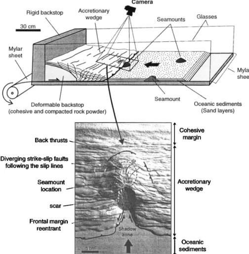
analog to those occurring in subduction zones.Figure 2 summarizes the main morphologic ti:atures induced by seamount subduction, presented in previous works
[Dominguez
et al., 1994, 1998]. The accretionary
wedge is
indented, and a large reentrant develop associated with a
critical frontal slope, where massive sedimentary
sliding
182DOMINGUEZ ET AL.: SANDBOX EXPERIMENTS
OF SEAMOUNT
SUBDUCTION
183
40'120'
130'
140'
150'
160'
170'
40' 30' 20' 20' 10' 120' 130' 140' 150' 160' 170'Figure
1. Shaded
view
of the
Pacific
and
Philippine
Plates
showing
the
morphologic
features
of the
seafloor.
Areas
of high
density
of seamounts
are
outlined
as
well
as
regions
of seamount
or ridge
subduction
(circles).
occurs. Landward of the reentrant, the margin is uplifted above the subducted seamount and shows a characteristic
fault network.
Seaward
dipping back thrusts
and conjugated
strike-slip
faults,
related
to the indentation
of the margin,
propagate
landward
as the seamount
subduct.
1.2. Experimental Setup
The two experimental
devices
used to perform
the sandbox
experiments
(Figure 2)are comparable
to those used by
Malavieille et al. [1991] and Dominguez
et al. [1994; 1998].
Both consist of an inclined rigid plate on which a mylar sheet,
simulating
the subducting
oceanic
plate slides, is located.
This sheet is pulled beneath a rigid backstop which
represents
the undeformable
part of the overriding
plate. A
cohesive sand wedge is built in front of this backstop to simulate the more compacted inner part of the accretionary
,wedge
and the more cohesive
seaward
termination
of the
overriding
plate [yon Huene
and Scholl, 1991]. The oceanic
sediments
carried by the subducting plate are built by
sprinkling
horizontal
layers
of colored
sand
on the mylar
film.
The sand layers and backstop wedge are composed of granular material (sand and rock powder). The sand used in our
experiments
is well-sorted
eolian quartz sand with a grain
size of about
250 ILtm.
Its physical
•properties
(angle of internal
friction
Os
of 30 ø and a very low cohesion)
satisfy
the Mohr-
Coulomb criteria [Dahlen, 1984, 1990; Dahlen and Suppe,
1984]. They can be considered
as good analogs
of natural
sedimentary rocks and marine sediments. The basal friction along the sand-mylar interface is intermediate (Ob=20ø). Scaling is such as I cm in the sandbox experiment is equivalent to I km in nature [Lallemand et al., 1992]. The
cohesion of the sand and the cohesion of the rock powder,
used in our experiments, are 20 Pa and about 100 Pa, respectively, and scale to 2 and 10 MPa [Gutschef eta!.,
1998]. These cohesion
values are very close to values of
unconsolidated marine sediments and lithified sedimentaryrocks [Hoshino et al., 1972].
The shape
of the subducting
high is conical
with a slope of
20 ø. It consists of a rigid core covered by a 2 cm thick layer of cohesive rock powder with a thin (< I cm)sand cover, simulating a volcanoclastic cover. The friction along the interface between the rigid core and the cohesive layer is moderate to high (close to •b=25ø).
The first device, used to study in cross sections the
different stages of a seamount subduction, has two lateral
glass
panes.
They allow the deformation
to be observed
in real
time on both sides of the experiment. The second device, dedicated to the study of the margin structure in three dimensions, is very much larger to avoid boundary effects. On
this apparatus
the model
can be impregnated
with water at the
end of the experiment to increase the sand cohesion and to cut
vertical and also horizontal cross sections.
The results of three selected sandbox experiments are
Camera
Rigid
backstop Accretionary
wedge
Seamounts Glasses
30 cm Mylar sheet Mylar sheet Seamount Deformable backstop
(cohesive and compacted rock powder)
Oceanic sediments
(Sand layers)
Back thrusts
Diverging strike-slip faults
following the slip lines
Seamount location scar Frontal margin reentrant
Cohesive
margin Accretionary__
wedge
I Oceanic
sedimentsFigure 2. Principles of the experimental setup used to perform the sandbox experiments. Specific apparatus, based on the same principles, allow study of the deformation in two dimensions (cross section) or in three dimensions. The main morphotectonic features associated with the subduction of a conical seamount are summarized [see Dominguez et al., 1998].
the progressive
defornl.,ation
of the margin during the
subduction of a conical topographic high. The second
presents horizontal cross sections performed in the
accretionary wedge above the subducted high. The internal structure and deformations of the margin are then digitized
and analyzed to determine the stress field around the
subducted seamount. The third and final experiment concerns the subduction of three conical seamounts trending obliquely
compared to the convergence vector. Vertical cross sections, parallel to the direction of the convergence, are Used to estimate material transtar inside the deformed margin at three different stages.
2. Geometry, Kinematics, and Mechanics of
Deformation Induced by Seamount
Subduction
The deformational stages of seamount subduction are observed along a vertical cross section on the 2-D device. To
study the section located directly above the top of the
subducting seamount, a half cone is used. Lateral efl:ects are not discussed in this 2-D experiment and will be studied in the next two experiments, using the 3-D device.
During the first 20 cm of convergence,
an accretionary
wedge
develops
by imbrication
of fi'ontal
thrust
slices
against
the cohesive wedge (Figure 3a). Some minor back thrusts,
related
to the growth of the accretionary
wedge,
slightly
deform the front of the cohesive wedge.
2.1. First Stage:
Uplift of the Frontal Margin
As the seamount
starts to subduct,
the frontal margin
is
uplifted. The basal d6collement is deflected into the thin sandcover (analog to the volcanoclastic cover) of the seamount
flank (Figure
3b). Part of this cover
is locally off-scraped
and
accreted beneath the frontal thrust unit (Figure 4a). Because of
the shape of the subducting
high, the d6collement
slope
abruptly
changes
to bypass
the seamount.
As a consequence,
the frontal taper of the margin increases as well as the friction
along
the basal d6collement,
which now crosses
through
the
seamount
sand layer. The frontal part of the accretionary
wedge deforms
to reach the steeper
critical slope that is
DOMINGUEZ ET AL.' SANDBOX EXPERIMENTS OF SEAMOUNT SUBDUCTION 185
5cm
5 cm
Trailing
flank Leading
flank .... Cohesive margin
/ •ccreuonary weage ...
..•...
...
:::::::::::•:•.•...
... .:,:•,•-
... •::•':•:" '...
•.
;•'•.. L•"_•.,•',•-• ..; •.•:
... ' ...,:
...
::•-'?•i•;::::•::' ß . • ... •. .... . _--•:•----: ... ½--•...:..• ... .::::•:::•:•---•ii!•i ... Seamount ' ' .... ' ' rigid core 10 cmUplift of the frontal margin • ...
I•. •ealmenIaaon
... •:•::.•:•::•'"•-"-'-'-'•'•:..:.• . ... •j;• -- ,• ... -•--•:•:-•- •- •. • ....
... •r.:• ... . •:• -.. •..:,::,:+•:•.:•.•a½-..•::,• ---<•:• -. -
. .. ..
:...
... ?:..:
.. ...::...;.;:..
'. :•:::
•
---•--•---•••---••••••..•
5 cm
Accretion
of
the t
Incipient
seamount cover top backthrust
... . ... '•• %, • ... ••••...•
:
...
:.
...
:..:•"".
- ..
• ...
•:g,•.
,...,
•
•
. -
...
.
...
...
.
. ."
. ....:
...
•
.... .,,,::Z
...
,
...
.,
...
.•..
...
, ,:::...
...
...
: .. :.•.
...
;;.;.--:,::::::,**:..•.
:•.;;;.
lO cmUplift of the cohesive•
margin
front
T
Backthrusts
Shadow
zone •,,,'•'•"•,"f,
'•/•'"'••.--...•
.**,,•.,••1•'• •
;-;....
...
... .
...
;
....
... .. .: .... : ... ...:::::• "...:.:.•,,.:;:..•'•,; .... 5 cm...
ß ..•.•..•:,...•.-•.::.:...i"
""•;• ...
;;::..:,•
. ..•.
. •..,. ½•:•...:¾'•: .•::.•....-•?•:? :•. ,.-'<% ::4;;% '•••• ... •: ß ... - ß ß ß ;•.•;.;;•:.:½: •.'..;•.5,1• ..:.;; .... " ..':.' . ... '"••%•;;::.:':." "•?"•:5•:;;'•"•'•'•:•:Z;•.,.;:...,,,,.•,...,•...•.•:.;;'• '*% ';•.- ':::' ... '"" ":'< '-•.":"" ... d.•.: ";::..":. ':'::• ":'"'"" •4:::.•:.•:::::•:•½•::::::::,• '• ;.•-&•'".::•:•:::•:':? ... • ... _...•.••••••••• •.Frontal accretion Suture
resumes
lO cm
Incipient
subsidence
Old backthrusts reactivated
Slope
New
accretionary
wedge
• break
- •,½•,, .. ....
... ..•••,•,
•••
•:,•.
...
.-;•.?• ... ß ... • ... ... . . ......
:.":•':'.".'::.
":::'":.:.:•.."•:•:,:.,::,
...
....
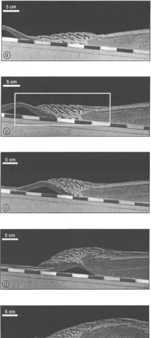
.. Remnant ß '.' ß :".:":':•:;•:.:':'•:h:. :. shadow zoneFigure 3. (a-f) Photographs
and structural
interpretation
of the first experiment
showing
the different
stages
of
conical seamount subduction in cross section. The experimental set-up consists of a glass-sided box so that
the deformation
can be observed
in real time. The trenchfill
(1.2 cm thick) consists
of six layers
of colored
sand,
and the seamount is composed of a rigid core covered by a cohesive layer of rock powder plus a thin sand
cover. The cohesive sand wedge dips 5 ø , and its initial length is 65 cm. Black arrows show the relative
vertical movements
affecting
the accretionary
wedge during seamount
subduction.
The greatest
part of the
Reactivation
thrustof
unitsthe
frontal
t
Uplift compressionalBackthrust
related
stressto
inducedthe
•
•
•
,•
by
the
subducting
seamount
5
c ....
••
• '•
'""'•
Normal
faulting
cm Low dippingnormal faults
Slope
break
cover (suture zone)
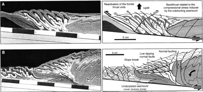
Figure 4. Enlargements
of a conical
topographic
high showing
details
of margin
deformation:
(a) initial stage
and (b) final stage.associated with the new geometry and basal friction of this portion of the d6collement. At this stage, reactivation of the thrusts is observed, inducing a general shearing of the accretionary wedge, coupled with a significant compaction (6% between Figure 3a and 3b). These mechanisms in the very early stages ofsubduction accommodate the shortening and thickening of the accretionary wedge. A ponded basin develops on the backside of the thickened wedge, which is filled with sediments (sand).
2.2. Second Stage: Indentation of the Accretionary Wedge After 10 cm of seamount subduction, half of the topographic high is now buried beneath the accretionary wedge (Figure 3c). The top of the subducting seamount cover is off-scraped and accreted to the frontal margin. Because of the compressional stress induced by the subducting seamount, compaction of the accretionary wedge increases (5% between Figure 3b and 3c). Finally, when thrust reactivation and compaction have reached their limits, back thrusts initiate at the base of the subducted seamount slope and accommodate ß the uplift of the accretionary wedge and part of the
convergence (Figure 4a). The basal d6collement, located on the leading slope of the subducted seamount, still accommodates the greatest part of the convergence. At this stage the frontal margin records a rapid uplift correlated with the height of the subducting seamount.
2.3. Third Stage: Initiation of a Shadow Zone and Indentation of the Cohesive Margin
After 40 cm of convergence the seamount is completely subducted and starts uplifting the rear part of the accretionary wedge and the seaward end of the cohesive wedge (Figure 3d). As the seamount subducts beneath the margin, the load on its leading slope increases rapidly. The basal d6collement .jumps down to the interface between the rigid core and the
cohesive layer at which friction is less. The cohesive layer of the seamount's leading slope is then accreted beneath the frontal margin, whereas its trailing slope remains relatively
undeformed. The seamount subduction strongly disturbs the stress field, and the basal d6collement is deflected upward in
its wake. The d6collement crops out in the middle part of the frontal slope margin, which develops an overcritical slope where sedimentary mass sliding is active. A large shadow
zone forms in the wake of the seamount. The trenchfill
sediments and part of the frontal margin are dragged into the subduction zone along with the seamount (Figure 3d).
After further convergence, the d•collement .jumps back down to the top of the subducting sedimentary sequence, in
the wake of the seamount. Shearing of the material located in
the shadow zone suggests that a small part of the convergence
is still accommodated along the previous position of the d&ollement. Only the trenchfill sediments continue subducting in the wake of the seamount without significant
deformation.
2.4. Fourth stage: Subsidence of the Frontal Margin
After 50 cm of convergence the seamount subducts beneath the cohesive margin. This cohesive part of the model simulates older accreted sediments and part of the detbrmable termination of the upper plate basement (Figure 3e).
Reactivation of remnant back thrusts, as well as initiation of
new ones generated by the seamount, is observed.
Because of the increasing load on the seamount's trailing slope and the increase of the friction surface between the shadow zone and the rest of the margin, a new basal d6collement initiates at the base of the subducting trench fill sequence. Frontal accretion resumes, and a new accretionary wedge develops at the front of the margin.
During a certain amount of convergence both d6collements are active, and an intense shearing of the margin material from
DOMINGUEZ ET AL.' SANDBOX EXPERIMENTS OF SEAMOUNT SUBDUCTION 187
Point 1
Deformation
front
/
Po!nt
2
• / Accretionary wedge /
..._,i•,•\ •,. •" - • Deformablebackstop
cm
lOO
/
i . I
i .••
i
i
i
Uplift of the frontal part of
95 -'1
...
:•,'
•. /•,.
Subsidence
of the
seaward
end
of
/ tne precolllSlOn prism # , % # '•. ...
90 •
'Pint
1'
• '
t • •
[ne
conerove
weege
/
•o.,
/ ;
y,
•
(.o•.t•)
85
80 / wedge
front
60
/
50 40 35 30 0©
©
•--- Vertical motion 10 ' 20 i 30 i iThe seamount starts
subducting
©
©
'40 • 60 ! ! !' Frontal accretion resumes
!
' in the wake of the
i
,, subducting seamount
The seamount reaches
the cohesive margin front
Rigid butress (Backstop)
/
Cohesive margin front (B) I I I 70 80 90 100 Shortening cm 5 cmFigure 5. Diagram
showing
vertical
and
horizontal
motion
of the deformation
front
and the seaward
end of the
cohesive
margin
with respect
to the rigid backstop.
The different
stages
of retreat
of the margin
and the effects
on the wedge
growth
induced
by the seamount
subduction
are quantified
by the two curves.
the shadow zone is observed. Finally, the upper d•collement dies, and the basal d•collement accommodates the whole
convergence. As a consequence, the greatest part of the margin
and trench fill sediments, dragged into the subduction zone behind the seamount, are underplated beneath the accretionary wedge. The size of the shadow zone reduces to
approximately half of the seamount volume. The underplating
of large volumes of sediment generates a rapid subsidence in the wake of the seamount, located beneath the rear part of the accretionary wedge (Figure 3e). The old back thrusts, now located above the seamount trailing slope are reactivated with a normal component. Conjugate normal faults dipping landward, and seaward dipping listric normal faults affecting the accretionary wedge are also observed (Figure 3e). At this stage the frontal slope exhibits a typical slope break (suture), which separates parts of the accretionary wedge developed before and after the seamount subduction.
2.5. Fifth Stage
After 60 cm of convergence the topographic high subducts beneath the cohesive part of the overriding plate (Figure 30.
A remnant shadow zone, composed mainly of part of the seamount cover and material scraped from the base of the
cohesive margin, is still observed in the wake of the seamount
(Figure 4b).
Other sandbox experiments, not presented in this study,
show that the size of this remnant shadow zone depends on
the friction along the basal d•collement level (here along the mylar-sand interface). High basal friction favors the development of a much larger shadow zone, because there is
no lower friction level at the base of the subducting
sedimentary sequence. The decollement remains in an upper
position much longer. The greatest
part of the accretionary
sequence is then definitively subducted or underplated
beneath the cohesive part of the margin.
2.6. Kinematics
During the experiment the seaward end of the accretionary wedge (the deformation front)and the termination of the cohesive wedge are recorded with respect to the rigid backstop, as well as their vertical motions (Figure 5). The seaward growth of the accretionary wedge (Figure 5, stage 1)
occurs at a rate of about 0.75 cm/cc (where cc reft:rs to centimeters of convergence). During this stage the cohesive margin front records only a very little landward displacement (a total of 1 cm) related to the initiation of minor back thrusts.
When the seamount starts subducting, frontal accretion ends, and the deformation front stops propagating seaward (Figure 5, stage 2). The back thrusts generated by the seamount induce a modest retreat of the accretionary wedge at a rate of about 0.1 cm/cc and a rapid uplift close to 0.2 cm/cc (Figure 4a). The subduction of the seamount strongly deforms the cohesive wedge. The shortening of this part of the margin accelerates to 0.3. cm/cc, and the wedge front records a retreat at the same rate (Figure 5, stage 3).
After 35 cm of seamount subduction (50 cm of convergence), frontal accretion resumes, and the seaward end of the cohesive margin starts to record a rapid subsidence (- 0.05 cm/cc). The effects of the seamount on the evolution of the accretionary wedge structure progressively decrease (Figure 5, stage 4). The deformation front again propagates seaward but at a lower rate, because the shortening of the cohesive margin still continues (Figure 5, stage 1). After 80 cm of seamount subduction the total retreat of the cohesive margin front is close to 20 cm. At this stage the landward motion of the cohesive margin tends to decrease significantly, but the seamount still slightly disturbs the development of the accretionary wedge in its wake.
3. The 3-D Structure of the Margin in the
Vicinity of a Subducted Seamount
This experiment is performed with experimental parameters comparable to the first 2-D experiment (Figures 6a and 6b).
When the seamount is subducted beneath the accretionary
wedge, the model is carefully impregnated with water to
increase the sand cohesion (Figure 6c). This method permits cutting horizontal cross sections, showing the internal structure of the accretionary wedge around the subducted seamount (Figure 7).
3.1. Description of the Cross Sections
The first horizontal section cuts the circular bulge located above the seamount (Figure 8a). Minor out-of-sequence thrusts are observed in the cohesive part of the margin. They initiate during the first stages of the experiment and are associated with the growth of the accretionary wedge. Curved back thrusts generated by the seamount can also be observed above and landward of the subducted seamount position. At this stage they only affect the accretionary wedge, which is uplifted and thickened.
The second section is located just above the top of the subducting seamount (Figure 8b). The accretionary thrust units are clearly deformed. They curve landward in the vicinity of the seamount. Close to the subducting seamount, out-of-sequence thrusts affect the middle part of the accretionary wedge. They develop from above the top of the seamount and propagate seaward on each side. Laterally, they connect with the preexisting thrust units of the accretionary wedge. A large part of the frontal margin is thus underthrust beneath the rear part of the accretionary wedge. In the wake of the seamount a strongly deformed seaward dipping thrust unit is observed. It corresponds to the frontal part of the margin, indented during the first stage of the seamount subduction and now subsiding in the wake of the seamount.
The third section cuts the top of the subducting conical high (Figure 8c). The thrust units of the accretionary wedge located above the seamount's leading flank are strongly deformed and stretched. Some conjugate strike-slip faults with small offsets can be observed despite the intense crushing of
":::::7;::;::..:•:•':..•:%•:...½d'•.'.•a•.•½':' ..',.. ß •wr:': . ' ..-.
ß
.
...
:;:::-
'x'---.:-'
ß
,,;':•....::•...:o::•-,4::.,-
.;:'::
':'i-::5.:
.:..;.77:-':•.•
:.:':-...:.'..•.7':::7-•"-
' :"'
.."".
:..::::::::::::::::::::::
:::!:
::.:::-'
::.::.: ...
:'
"'
:...-.:
•:..=================================================== .,.:::.-:.::::::::.:.. ::::::::::::::::::::::::::::::::::::::::::::::::::::::::.•.. '...,.•• •,•.,..:• ....:..-.,: ... :...: .-.-: .:,.. ,:•....::...•.,...:::.,.. ... ;:::.5,:•:.:•?..,'•:$,•,•: .•e,- -...•. w, •:.?..:..• .•; .:, .. :::,-::::-:, .:::. :: :,. ... .::.::.: :•: ::.: .: :....: :,..::::•:' ... . :::"•2,...• x•/:;:'..::..•..-: .:•-:...•...-' '.,.
.
.. -.:.. :- ... ':•:::.,:•.':• ßß
G:.
'::•
...
.•.•
... :• .'•:•}•,½ ... 'm• '• ... •'•:--•:'"'":"': ... '*' "'•..%•.i ß ...-.,...':•.t.M':':-'..' ... ß ... x.,. -'.. ß '.' ...-..'.:-.. ... -s?.'.. . .. . .... :- -...•:.-,..,,•,...•.,.-....,•,•--.- .--•.-..,,•..•.%...•-- :'•,:.:.::•-:%;.,'..•' ß ' ::;;:::4'•[:5'. '-.-:"--•'. •'.•:' "> ..,.,...,.-.,-',..,-'-', '•i':.?[[..:.i':..i::•:<,-,•.d,.:. :.:•..5.'.,:.. '"• ' :: d.•,•,•:•:,-:Z.:•..,...•.72•"•'"-'
, ,•,.• ... ....>...,4,... • .... . ... .. . .:......
7• ... . - ... ... . .... . ... . .:. ::,<,".-..• •<•'<,,•. . '.,..;.-:->:.;--":::::"q::'::::":'"...:.:'" :5-'.'" i•.> .... .<.z::,:-:::-.<:'.•'•-:i., ' .... ...' ...::'
=====================================================':"::::::•S'::.'
". *: .•' "'..' ::..." ..' :•. ":" .,....?: :*"' '"'-½:.:.::.:-½
:' >-'' ' ...
'• "':'-•:::::'-::
:'•:-•:
:.-'::: :::-.: :< -'*•"' •••••?' "•, •--,- '•"'"'•"
'•:} :?::?:
'•"
- - -. ,. '.... ..- :' •:,•.'
-'•:'? ",'4•...::
:' :'..:' ... :::-.: ... :..'....'-:. :::::::::::::::::::::::::::::::::: .... =========================== ,/. .:.:.:a?':•: .... •. • .,.,, • •.,,..::::•_.. "*'• ,.*:,..,••:c:.•' '<' "-- • <, •,•,,;:. • ..>. :•:.f½:?•$:.<;::,,.-::..::..;{•:•. - :...':'. - *•:y;.%•. ::'%*..-- ß ....,: :.,:...*,...::,:•:;:½..:.::,...,:.:::,s, ,.,, ,:• ,- .,..,Figure 6. (a,b) Planar photographs of the second experiment. (c) A perspective view of the second experiment. When the topographic high is completely subducted beneath the accretionary wedge, the model is carefully impregnated with water to increase the sand cohesion. Sections are then cut to study the deformation of the wedge structure.
DOMINGUEZ ET AL.: SANDBOX EXPERIMENTS OF SEAMOUNT SUBDUCTION 189
Background
ß
margin
uplift
REFERENCE
CROSS
SECTION
Cohesive
margin
associated
with
the
subducted
/
j
relief
"'
•';•:'•":'•
I
'
?"'' ...
; '"':::•ii•"'.'"
,,•:,,½.•' ,-'• ......
:--:- ... ;•5-z:::•.:.•: ...'•'Z:..,•*•:t
•:• . ,,•.• ;.zz::,, ....---
Accrebonarywedge
- ß• ß :'..'½;,•
...
----•r•.,.:'
....
:.:.;•:.:•.•::.
:.-.;.:•:;:•;•:.:
...
Oceanic sediments
ß •-.".. "*. ß %:- "'?..' ... ,•," ;•;' :'•""•" ß - ' " "•..•½•::•7':'"""' - ... . ., - - .--, . :,:: '•½., •,,,-,•. •,., ß •½ ß ,-•..•.,•::::;•:•½•.•, .,•.,•..., ß '4:.•,i .... .., ß '.' ,4:..• ... • .'.,;.-.,•.:•;-".•..:' .:;• ... ,.=..,,.- .... - ' ,:::".' . . . ... :• ... ,•. ... '• ... , ... :½:,,. • ... , ... '. ;;:•, : •4 ½•:½b4.4:.•,,•½ "•' •'" ... ½ '" ...'•;• • r.. .,½ * :.'*&•. .. '" ' .... ,•'.'*' -•::.•..-,.•.'" ß ..*•=;, "'• '•' ' •'-' ß "..' '":'.,•.., '",' ' ... '". •'""¾'> . .• .... ;4a ... ½ ß ,'..::','"'..,..•;",;-•;'½%;-;,;..%:L:-½•v" ß ..':,.;&•' • ½•-'½•:%-;'.•"'.' ".. "::"-• ":• ... ". ":' ,. ,A • t'. *.,•r'"%.• ... '•' ß '•'• ... ' ... ' ß : . ': .',.--.., ,:•.•.•-½,,.:"•'•:• .::-• ". . . . ....,j ... ... ... : ... • ... ., ... g.::..? .:.:...•::;•:•:•;•:7•::;•:•::•;•:•;•:•:•::•:•;•;•4•;;•:;;:•;•;•;•:•:•::•:•.•.•;:•:::`•:•;;•;:•:::::•:•:•:•:...:(•;•:::.•::;.:..•:.;:.:.:•:::•;.:•:•;•:•:•:.(•:.•;:.;•:;•:•:•::•:•;•;•;•....;•.•::..•.:•..•:•:•.•..:•.:.•:.:.::::::::::::::::::::::::::::::
Out-of-sequence thrust
STRUCTURAL INTERPRETATIONPop-up structure
\
Highly deformed
zone
•
Thrust units
Deformation
front
_---- , , \....-:::..-:.:::: ... •-:• .---..-.--. .... --
Basal d6collement
level
Figure 7. Photograph and structural interpretation of the reference section, trending parallel to the direction of convergence. These depictions show the structure of the accretionary wedge and the seaward end of the cohesive wedge in a region situated outside the deformation generated by the seamount. Dashed lines show the location of the horizontal cross sections presented.
the accretionary wedge in this area. Seaward of the seamount top, two faults trending parallel to the direction of convergence bound the upper part of the shadow zones which
is located in the wake of the seamount.
The last cross section cuts the margin at the top of the subducting sedimentary sequence (Figure 8d). This section provides good constraints on the margin structure in the wake of the seamount and on the shape of the shadow zone.
Seaward of the subducting high, part of the seamount cover and the trenchfill sequence located in the shadow zone can be observed and appears to be undeformed. Two transfer zones, which connect to the base of the leading seamount flank, bound the shadow zone. These faults have a strike-slip component close to the trailing seamount flank. Farther seaward, they also exhibit a superimposed thrust component, which suggests that the shadow zone is progressively reduced in width. A reconstruction of the d6collement surface geometry is shown in Figure 9. The main out-of-sequence plane is also represented.
The d6collement molds the shadow zone in the wake of the
seamount. At this stage the volume of the shadow zone is comparable to the size of the seamount if we consider the trench fill sediments located in the margin reentrant.
3.2. Stress Field Deduced From the Fault Network
We roughly estimated the shape of the global stress field around the subducted topographic high (Figure I0). This reconstruction is based on the interpretation of the previous horizontal cross sections, the study of the fault network, and morphologic studies (Figure 2 and Dominguez et al. [1998]). Above the leading slope of the seamount the bending of the accretionary thrust units associated with curved back thrusts and conjugated strike-slip faults (better observed in the morphology) indicates that the major component of the stress
field (CSl)
diverges
landward.
The indentation
of the !nargin
occurs above the leading slope of the seamount and does not extend far away on both sides. Laterally, the thrust units appear to abruptly strike normal to the direction ofconvergence.
Conjugate shear zones associated with strike-slip faults trending oblique to the direction of convergence suggest that
CS
l tends to converge in the wake of the seamount.
Furthermore, subsidence and extension observed in this area
confirm
that CS3
tends to parallel
the relative
plate motion in
the wake of the seamount. Finally, the successive shapes of the deformation front during closing of the reentrant when•:... ' ... •:, ... .... -•. ,.- -*;?¾•4•:,:::::;"-::* ':•7:i'*'•"•;½• ... :aa•.,%.:;•.• ...;:-:•:::::'-;:;'i:;:•';:•E;f;:•;(?;-•(½-:,:•:•,:;•& 9'* *½':":':':':""7C :t•... -.-•:•":•
...
, ... ...
;..:..
;,
....
:::::::::::::::::::::::
.
...
P"•:•a•*::i:•a•4i½:::::::,:..:a?•½,:---:--..•.- ..a:::::ii::';-•;.•.::.- ;'. <- :'-.'•*:½•%•{a•:::½:E:•::f ::•:::: ... '-': ....'.:-....'.::'.:::::.'.'....:::::;:.•.::.':'- ... • ' "•:::---•:½;i;•;:.:;•(;•.;:.. ' ... "•::4,:: ... :.&.:;:::.: ... •-:::•:::*'?';..-:?:L. - -'•" ' ... ' ... ::... •m•}::•?.::,.. ::.;; ... : ,..;;-;;•*•:as½-•-:..•-. ... ' ... ;:;,•;;--::•:'; .:? ½;.}-:. --::': :•"'-:-:•:--•...; ... '3;:;;.':'../:-' . %" . :::}•'": ... ..-.. .. ... :: ... ' "::::"?½:" ... ...*.. ' ... •;•-'"::'x•: :,.,+;2 L'.-'. ' -- .. ... . ... ½ .... :"';7'; ... ; ..,.•;2:.'. ... . ... : ... . ... .... . •,•:•½ ... ... ..:-/:?:!:•:.::•:•.. ::. ,?•i'-';:.•." ... :... ... "":"":""'::•*• ... .-:..:-::,•.?.%,• '"' •'::'*':':":':' ... ":"-;;;" ... ':: 'i,i •;•'*::•:::•:•'•'• .••.:•.%•:... .... "••••••,...• ... -' ..-.:,,-.--;'";.L.:
'i ...
:'•?:/":•'-?:';':':'"":":"
...
':::.;:c
...
;:...:;...::::.::'"""::::•'•;i
ß ..&:y.'**:4;..•...
...:, ..-'.:.:.'
...
:'"'"%.:;;;;* • "•C:>:-::*½:"/"' ... •::: ... . ... .:.{...,'---?. ,.,.:...•:•. ... .::,..:..:...:
. ' ...
•,.':'
... ... ½.:::.- '..!.. ;½. ½ .. ... ... -:¾'-fa:::':':. ?:::::: .... '*** :•-'•::**' ?-:-w*Figure 8. (a-d) Photographs of the horizontal cross sections discussed in the text.
frontal accretion resumes indicates
increasingly parallel to the convergence.
that (•1 becomes
4. Deformation and Material Transfer
Within the Accretionary Wedge
The subduction of three conical topographic highs,
trending obliquely with respect to the direction of convergence, is performed to study material transtar inside the
margin at three different stages of seamount subduction. At the end of the experiment the model is impregnated with water, as for the second experiment, and cut by 30 vertical cross
sections, all parallel to the direction of convergence (Figure
•).
4.1. Description of the Cross Sections
A reference cross section is cut far from the effect of
DOMINGUEZ ET AL.' SANDBOX EXPERIMENTS OF SEAMOUNT SUBDUCTION 191
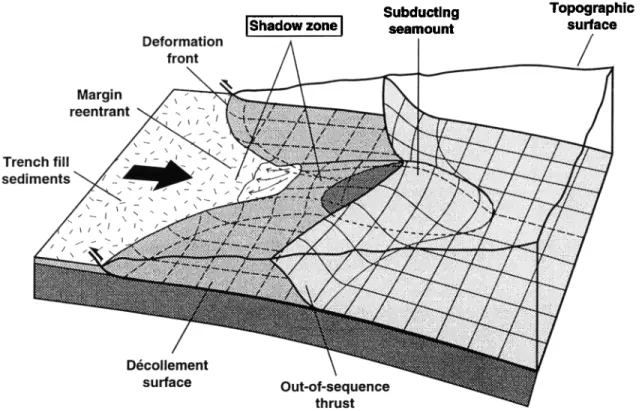
Deformation front
Subducting
I Shadow
zone
I
seamount
Topographic surface
/
Margin reentrant D•collement surface Out-of-sequence thrustFigure 9. Block diagram showing 3-D geometry of the main thrust surt•tces (d{Scollement. shadow zone, and
out-of-sequence thrust).
accretionary wedge (Figure 11. See reference cross section). Back thrusting of the rear part of the accretionary wedge onto the cohesive margin generates an "outer arc high" trending parallel to the backstop. It bounds a narrow morphological trough corresponding to the forearc basin, which is filled with sediment (sand) during the experiment.
Section A shows the structure of the margin above seamount 1, which is in the first stages of subduction and uplifts the frontal margin (Figure 11, section A). The basal d{Scollement is deflected upward and emerges at the surface in the middle part of the frontal margin. Above the seamount trailing slope, a small shadow zone develops, mainly composed of parts of the seamount cover and some frontal margin sediments.
Section B shows the margin structure above seamount 2 buried at the boundary between the accretionary wedge and the most compacted part of the margin (Figure 11, section B). At this stage, frontal accretion has already resumed, and a new accretionary wedge develops. A volume of frontal margin material, comparable to the size of the subducting high, is underplated beneath the rear part of the wedge. As a consequence, the accretionary wedge exhibits a steep slope (19 ø) in this area, whereas the frontal slope dips only 5 ø. The slope break marks the suture zone.
Section C is located through the seamount 3, which is deeply buried beneath the cohesive wedge (Figure 11, section C). Here the effects of seamount subduction on the margin structure are most important.
In the middle part of the accretionary wedge, near the suture area, the lower parts of the thrust units are missing. A very
,, •Shadow ' t zone
, ;
.Frontal margin
reentrant
Figure 10. Shape of the stress field around the subducted
seamount. The main thrusts and fault network, deduced from
the experiments presented and previous morphological
o
o
o c
DOMINGUEZ ET AL.' SANDBOX EXPERIMENTS OF SEAMOUNT SUBDUCTION 193 20 25 30 35 40 45 5O
0
5
10 15 20 25 30 35 40 45 50 55 60 65 70 75 80
I • • I I I I I I I I ! I I I I I '.';'i iiiiiii • ... :i ' :•:: :. U.S. E3 ) 55 6O cm caThickened
area
R ß Frontal margin reentrant U.S. - Underplated
sediments
Eroded
area
•' Direction
of convergence
E ß Eroded
part
of the
margin
..•-•
Difference
(cm)
between
the
undeformed
and
Subducted
seamount
/
the
deformed
margin
surface
Figure 12. Map illustrating the transfer and underplating of frontal margin material to the rear part of the margin. Dark shading with positive contours corresponds to the region thickened at the end of the experiment. Light shading and white areas with negative contours correspond to regions of the margin eroded during the seamout subductions.
long underplated unit is observed instead, which
to the size of the shadow zone when the seamount
was
corresponds
to the part of the trench
fill sequence
previously subducting
beneath
the accretionary
wedge.
dragged into the subduction zone behind the seamount. In
this region the lower part of the accretionary wedge is 4.2. Material Transfer in Three Dimensions strongly eroded and has been transported into the seamount
shadow zone and finally underplated landward. The 30 cross sections are processed to reconstruct the 3-D
Part of the accretionary wedge sediments appears to structure of the margin and to calculate the material transfer
subduct
with the seamount
beneath
the
cohesive'
wedge
in a
(Figure
12). The topography
of the deformed
margin
is
reduced shadow zone. The intense de/brmation of the digitized using the vertical cross sections. The reference cross
sediments located in this remnant shadow zone suggests section is used to reconstruct, by interpolation, an
internal shearing
induced by a vertical velocity gradient undeformed
margin topography at the same stage of
inside this kind of subduction channel. At this stage the convergence. Figure 12 shows in map prqiection the amount of material dragged into subduction appears to be difference (calculated in centimeters) between the deformed greatly reduced (about half of the seamount volume) compared and undeformed surfaces of the margin. Assuming that the
margin
material
cannot
cross
the rigid backstop
(no output),
the topographic
differences
between
these two surfaces
are
directly
linked
to material
transfer
inside
the margin.
To avoid
artifacts induced by the seamount shapes, the topographic
effects of the seamount have been removed from the deformed
topographic surface.
The negative
contours
(light shading
and white areas
in
Figure 12) show the region of the margin
where a material
deficit exists (sediment has been removed), and the positive
contours
(dark shading
in Figure 12) show the region of the
margin where a material
surplus exists (sediment
has been
added).Seamount 1, which is the first stage of subduction, slightly deforms the frontal margin. A small thickened region (l cm) located above the seamount's leading edge is observed. It
corresponds
to shortening
associated
with the reactivation
of
the accretionary thrust units.Seamount 2 is more deeply subducted and has strongly disturbed the accretionary wedge in its wake. The frontal
margin
appears
to be eroded
over a large area,
about 3 times
larger
than
the seamount's
basal
surface.
The amount
of eroded
sediment is estimated to be twice the seamount volume and isalso comparable
to the volume of excess
sediment
observed
directly seaward
of the seamount
position. This thickened
area,
which extends
laterally over more than 20 cm, reveals
that the material
previously eroded
from
the frontal margin
is
now underplated at the boundary between the accretionary wedge and the cohesive margin front.
A thickened area can also be observed above the seamount leading slope. It corresponds to the active deformation of the seaward end of the cohesive margin which records shortening.
Seamount 3 shows similar features. Nevertheless, because it
represents a more advanced stage of deformation, some differences are observed. The deformation front is still slightly indented, but its morphology is nearly normal, because frontal accretion has resumed and a new accretionary wedge has developed. The eroded area of the margin is still observable and can be compared in size and volume to the one associated with seamount 2.'The cohesive margin front is strongly indented, and the._underplated sediment proceeding from the frontal margin lodges in this area. The volume of the margin affected by underplating of material and thickening of the cohesive margin appears to be very large (about 8 to 10 times the seamount volume). This last observation leads to the conclusion that the seamount subduction deforms the margin not only along its track but also regionally.
5. Discussion and Conclusion
The use of analog modeling can make a great contribution toward understanding the evolution of the deformation and
quantifying the resultant material transfer. The sandbox
Volcanic
/
arc
ForearcBasement Coastal
uplift
9
ß basin"LIMITED
'•ACCR'ETION
OF PART OF THE SEAMOUNT ?
'LARGE. EARTHQUAKES i i 20 km Vertical Exaggeration = 2 Accretionary wedge Trench Seamount
/
/
FLUID SEEPAGE UPLIFT
UNDERPLATING OF LARGE VOLUME OF SEDIMENTS MATERIAL TRANSFER FRACTURATION OF THE MARGIN FLUID EXPULSION POSSIBLE CHANGE IN
THE MECHANICAL COUPLING
UNDERTHRUSTING OF
FRONTAL MARGIN MATERIAL TECTONIC EROSION