Design and Biomechanical Analysis
of Supernumerary Robotic Limbs
The MIT Faculty has made this article openly available.
Please share
how this access benefits you. Your story matters.
Citation
Davenport, Clark, et al. “Design and Biomechanical Analysis of
Supernumerary Robotic Limbs.” Volume 1: Adaptive Control;
Advanced Vehicle Propulsion Systems; Aerospace Systems;
Autonomous Systems; Battery Modeling; Biochemical Systems;
Control Over Networks; Control Systems Design; Cooperative, 17-19
October, 2012, Fort Lauderdale, Florida, ASME, 2012, pp. 787–93.
As Published
http://dx.doi.org/10.1115/DSCC2012-MOVIC2012-8790
Publisher
ASME International
Version
Final published version
Citable link
http://hdl.handle.net/1721.1/118790
Terms of Use
Article is made available in accordance with the publisher's
policy and may be subject to US copyright law. Please refer to the
publisher's site for terms of use.
DESIGN AND BIOMECHANICAL ANALYSIS OF SUPERNUMERARY ROBOTIC LIMBS
Clark Davenport, Federico Parietti, and H. Harry AsadaMechanical Engineering Department Massachusetts Institute of Technology
Cambridge, MA 02139 {clarkd, parietti, asada}@mit.edu
ABSTRACT
A new type of wearable robot that provides a third and fourth arm for performing manipulative tasks with the wearer's own arms is presented. These Supernumerary Robotic Limbs (SRL) work so closely with the human that he/she can potentially perceive them to be his/her own. The SRL consist of two independently acting robotic limbs that can function as either arms or legs to help the user position objects, lift weights, and maintain balance. These wearable robots are aimed to augment not only the strength and the precision of the human users, but also their range of skills and interactions with the environment. The guiding principles of the robotic design are safety, transparency and user comfort. Series viscoelastic actuators provide suitable joint torques while ensuring compliance and robust torque sensing. A Bowden cable transmission actuates the elbow joint, minimizing the robotic arms’ weight. A tuned elastic human-robot coupling ensures wearability and comfort. To quantify the mechanical advantage the SRL offers to the operator during use, joint torques generated in the human while performing static manipulation tasks have been reconstructed experimentally.
INTRODUCTION
The brain’s internal representation of the human body, called body schema, can be modified to include tools and artificial limbs [1]. As such objects become incorporated in the body schema, they are perceived as extensions of the natural limbs and are included in motor planning for manipulation [2]. Such a phenomenon allows for more masterful manipulation of external objects. Similarly, one can experience ownership of a rubber hand given appropriate visual-tactile stimulation in an experiment known as the rubber hand illusion [3]. Most interestingly, the RHI has been extended to see if the human can experience illusory ownership of an additional limb. If the artificial hand resembles a real hand and is oriented in an anatomically compatible way, it can be incorporated into the
body schema [4]. This suggests the ability to build a robotic device that can be perceived as part of one's body. Such a device could find important applications in a context such as aircraft manufacturing, where multiple humans are required to collaborate in order to accomplish complex assembly tasks.
In order to exploit this possibility, we built wearable robotic arms that will assist users in performing manipulation tasks in an aircraft manufacturing setting. Unlike conventional exoskeletons, these Supernumerary Robotic Limbs (SRL) will act as third and fourth arms or legs and therefore augment the workspace and the skills of the human. Operators will be
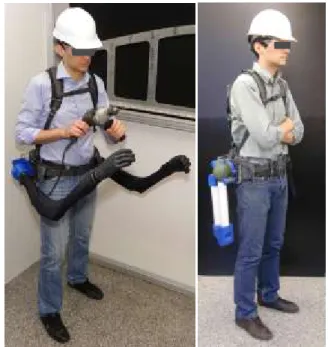
FIGURE 1: LEFT, CONCEPT OF THE SUPERNUMERARY ROBOTIC LIMBS (SRL). RIGHT, FOLDED CONFIGURATION OF THE WEARABLE ROBOT.
ASME 2012 5th Annual Dynamic Systems and Control Conference joint with the JSME 2012 11th Motion and Vibration Conference DSCC2012-MOVIC2012
DSCC2012-MOVIC2012-8790
equipped with the SRL to help them position parts, lift objects, and maintain balance. A backpack-like harness will be employed to secure the SRL to the wearer with a hip strap fastened about the operator's iliac crest, shoulder straps, and a chest strap. Because the SRL will move in close coordination with the human limbs, it is possible that after some use they may be conceived as part of the user’s own body.
First and foremost, the SRL must be lightweight and compact to be comfortably worn in their typical use cases. The application that we consider is static load bearing. In order for the SRL to be beneficial, it must either provide users with abilities that were previously unavailable to them or enhance their current abilities by reducing human exertion. It is this second goal of reducing human effort that we wish to address in the present study. For this reason, it is of interest to examine the torques imposed on the user’s joints while completing load bearing tasks with and without the SRL. The system has substantial mass and will apply non-negligible forces to the wearer’s shoulder and back. Because we aim to reduce exertion and overall load on the human, it is desirable that the reduction of torque load on the joints caused by assistance in lifting should surpass the negative effects of the reaction forces created by the backpack.
The coupling between the human and the SRL is complex, and must be carefully designed to create a comfortable, wearable system. A number of studies on backpack modeling give useful indications in this respect. Not only is the interaction between the human and backpack dynamic due to slipping and deformation, it is also extremely nonlinear and contains redundant suspension systems. Further, walking gait and posture are changed in order to compensate for muscle fatigue and extra joint forces caused by the load. Ren et al. discovered that decreasing backpack suspension stiffness reduces the vertical reaction force acting on the torso [5]. Foissac et al developed a much simpler one degree of freedom linear model used to predict the vertical travel of the backpack [6]. The design of the human-SRL interface should take in account these results to maximize comfort and wearability.
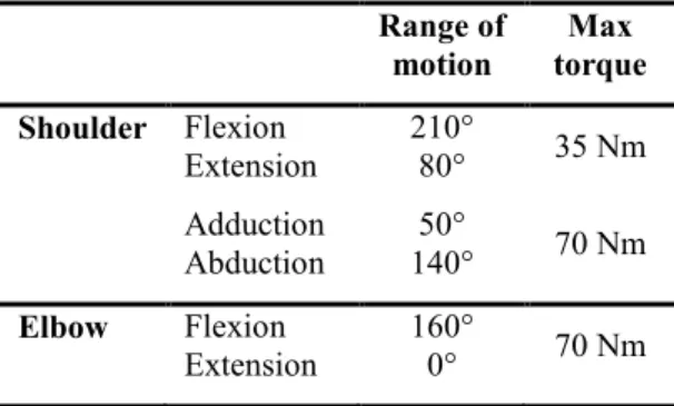
TABLE 1. SPECIFICATIONS OF THE MOST POWERFUL JOINTS OF THE 50TH PERCENTILE MALE ARM
Range of
motion torque Max Shoulder Flexion Extension 210° 80° 35 Nm Adduction Abduction 140° 50° 70 Nm Elbow Flexion Extension 160° 0° 70 Nm
Two main contributions are presented in this paper. The first is a design of the SRL that achieves human-like and safe motions. The second is the evaluation of the extent to which the SRL reduces human exertion during the task of static loading.
We first focus on the functional requirements of the SRL's design. We then discuss the specific design choices made in building the prototype of the SRL. The biomechanical model of the human-SRL system and the experimental setup employed to study the SRL performance are presented. We calculate the joint torques caused by static loading on the user, and define a metric to quantify user exertion. Finally, experimental results are analyzed, and their implications for the future development of the SRL are discussed.
DESIGN CONCEPT
The aim of the SRL is to assist human workers during fatiguing or dangerous manufacturing tasks. The coordinated action of supernumerary robotic limbs will allow a single user to perform tasks that would have required multiple operators, effectively augmenting human skills and increasing work productivity and quality. Aircraft manufacturing is characterized by a number of operations that require multiple workers to coordinate their actions. During these tasks, the lead worker performs the most critical operation, while one or more assistants support him by taking over the most physically demanding or repetitive functions. This is exemplified by the fastening of titanium beams to the airplane frame, where the leader uses the fastener while one or more helpers lift the beam and keep it in place. Another representative case is the drilling of holes into carbon composite plates. Carbon powder is harmful for the human respiratory tract, so an assistant is always paired with the drill operator in order to vacuum the particles at both sides of the hole. In these cases, the SRL could take the role of the assistant worker, actively supporting the user and streamlining the manufacturing process. The SRL could also play an important role in increasing safety on the workplace, restoring balance when equilibrium is lost or automatically grabbing scaffold beams when the user operates at elevated locations.
If the supernumerary robotic limbs are to successfully coordinate with the user during the execution of complex tasks, their dynamic properties should be similar to those of the human limbs. There are three main reasons that motivate the bio-inspired design of the SRL. First, it is likely that matching the robot dynamics with the human behavior will make it easier for users to perceive the SRL as part of their own body. Second, in order to take over the most fatiguing functions during manufacturing operations, the SRL joints must have torques, velocities and bandwidth similar to those of the human limbs. Third, aircraft assembly facilities and tools are designed for humans (the use of industrial robots is still limited in the aerospace industry). A wearable robot with properties similar to human workers could therefore easily interface with existing instruments and be integrated into the manufacturing
procedures. Table I shows the specifications of the most powerful joints of the human arm [7].
Figure 1 illustrates the concept design of the SRL. The system is worn through a backpack-like harness with padded straps and hip belt. The mechatronic structure, connected to the harness with a compliant element, is composed of a backpack unit and two robotic arms. The unit is placed behind the lower back of the user, and hosts the system actuators. A cable reaching the backpack provides power and control commands, allowing the realization of a light and compact system without onboard batteries or computing hardware. The cable tether does not represent a disadvantage, because power and pressurized air connections would be needed anyway to operate conventional manufacturing tools. The robotic arms are attached to the main structure in correspondence of the iliac crest, the thick edge of the hip bone. This minimizes the interference with human motion and maximizes the robotic limbs’ workspace, allowing them to act both as arms and as legs. When unused, the artificial limbs will fold and hang from the sides of the user, similar to the ordinary tools stored in the worker’s utility belt (Fig. 1). The robot has been equipped with general-purpose grippers. However, in the future it will be possible to employ more advanced robotic hands, and to automatically change end effectors to best accomplish the task at hand. The SRL configuration concentrates the system mass in the back unit. This allowed the realization of powerful yet lightweight robotic limbs, with dynamics suitable for safe and effective human-machine interaction. The details of the robot prototype will be discussed in the next section.
PROTOTYPE REALIZATION
The SRL design principles are safety, transparency, and comfort. These objectives have been achieved by optimizing the robot mass distribution to reduce the arms weight, designing the actuation system to bear the loads typical of fatiguing manufacturing tasks, and employing series viscoelastic elements to ensure safe human-machine interaction.
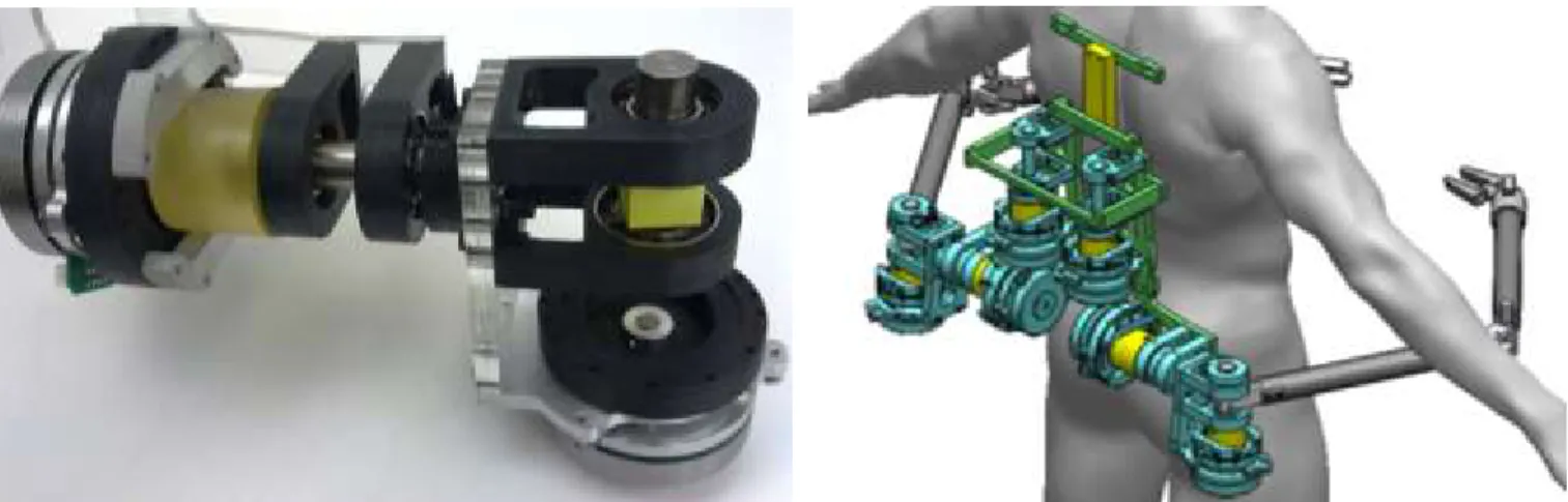
The SRL has 6 degrees of freedom: each arm is provided with two rotational joints at its base and one in the middle (Figure 2). The robot joint specifications are modeled after the most powerful human arm joints: the shoulder (both flexion and extension movements) and the elbow. The shoulder flexion actuator (peak torque: 69 Nm, weight: 1.5 kg) is placed horizontally in the backpack unit. On its shaft is placed the shoulder abduction actuator (peak torque: 39 Nm, weight: 1.2 kg), which rotates together with the arm when the shoulder flexion dof is moved. However, because the center of mass of the actuator is close to its rotational axis, its inertial contribution to the arm movement is very limited. The last actuator, the one for the elbow joint, is placed vertically in the backpack unit (specifications analogous to shoulder abduction). Its output is connected to the joint through a pull-pull Bowden cable transmission system (length 1.5 m, peak force 1023 N, 1x19 steel wire rope) [8]. The structure of the back unit is realized in high-strength Aluminum 7075 alloy, while the arm links are constituted by hollow section carbon fiber beams. All parts have been verified for static and fatigue strength to guarantee resistance in conditions of continuous operation. The overall mass of the system is less than 15 kg, and 80% of it is concentrated in the backpack.
The choice of the degrees of freedom and their specifications has been motivated by the need to execute physically demanding tasks, such as lifting weights or helping the wearer to balance. These tasks will require stronger forces in the sagittal plane than in the coronal or frontal planes, so the shoulder flexion joint has been provided with a more powerful actuator. The overall design of the robot has been focused on mass and volume reduction, in order to ensure comfort and wearability. Positioning all of the actuators in the lower back zone reduces the interference of the system with the human workspace, lowers the SRL center of mass (thus improving stability), and allows for the construction of extremely lightweight robotic arms.
FIGURE 2: LEFT, SERIES VISCOELASTIC ACTUATORS (SVA) USED FOR THE SHOULDER JOINT OF THE ROBOT JOINT. RIGHT, PROTOTYPE OF THE SUPERNUMERARY ROBOTIC LIMBS.
The custom actuators developed for the SRL are compact (max dimensions: 110x112.5x170mm), lightweight, and satisfy the demanding torque and speed requirements of the target manufacturing applications. All joints are controlled by Maxon DC brushless motors of the flat type. This choice maximizes peak and continuous torque (respectively 3.9 Nm at 42 V and 18.3 A, and 0.494 Nm at 42 V and 2.12 A) while minimizing axial size and weight (0.6 kg), resulting in a “pancake” form factor that facilitates heat dissipation. The motors are connected with flat Harmonic Drive gearheads, providing high output torques (see actuators specifications), low mass (0.91 kg for shoulder flexion, 0.52 kg in the other cases), backdrivability, and zero backlash. The selected gear ratio was the smallest available (1:50). Circular hollow-section polyurethane torsion bars are placed between the gearhead output and the actuator output, realizing Series Viscoelastic Actuators (SVAs).
The presence of series elastic elements decouples motor inertia from the output side, allows for robust torque control, and guarantees safety in case of impacts [9,10]. The stiffness of the torsion bars is 150 Nm/rad. Their angular displacement is measured on both sides by the motors’ Hall sensors (72 ppt before gearhead) and hollow-shaft optical encoders (10’000 ppt). Because of the polyurethane low shear modulus (0.003 GPa) and high maximum deformation (590% elongation at break), the torsion bars can achieve the desired stiffness while retaining compact dimensions (max diameter: 60 mm) and light weight (max mass: 79 g). Although their behavior is viscoelastic and cannot be described with Hooke’s law, effective models and observers have been developed for accurate force control of SVAs [11]. The use of conventional steel helical coil torsion springs would yield a simpler linear behavior, but at the cost of significantly increased mass and size.
Another compliant element is placed between the backpack unit and its connection with the shoulder straps worn by the user. The function of this series stiffness is twofold: on the one hand, it guarantees comfort by limiting the maximum stiffness of the human-machine coupling. On the other hand it allows the SRL backpack to flex, following the curvature of the spine in the sagittal plane and adapting to variations of the shoulders’ inclination in the frontal plane. The stiffness of the compliant element is 40’000 N/m [6]. In order to add physical damping, another viscoelastic material (rubber) has been selected to realize this passive element.
BIOMECHANICAL MODEL
To determine the torques generated by human joints while completing tasks task using the SRL, a biomechanical model of the user and SRL was developed. The human was modeled as a kinematic chain of five rigid bodies connected together in the sagittal plane (Fig. 3). The body segments included in the model were the forearms, arms, torso, thighs, and shanks. Anthropometric values were calculated based on [12,13]. The
external force due to a weight held in the hands was modeled as a purely vertical load acting on the end of the forearm link.
Due to the complex nature of the SRL-user coupling, the backpack was abstracted into point forces acting on the human kinematic chain. The supporting frame of the SRL only comes into contact with the human at the shoulders and the hip, and therefore only the total forces exchanged with the SRL in those regions were considered. The shoulder forces imposed on the human by the SRL have been decomposed into a vertical and a horizontal force acting directly on the shoulder joint. Since the SRL are secured to the iliac crest with a padded belt, hip forces imposed on the human by the SRL were abstracted into a single horizontal force acting on the hip joint.
Because the focus of the study was the analysis of the effects of the SRL in static lifting tasks, equations of static equilibrium were used to identify the joint torques. Applying these equations with each rigid body, reaction forces and torques at the joints can be calculated given the angle of each joint with respect to the horizontal.
The equations for the torque at the joints are given by the recursive formulae:
𝜏1= 𝑃𝐿1𝑐𝑜𝑠𝜃1+ 𝑚1𝑔𝑑1𝑐𝑜𝑠𝜃1 (1)
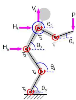
FIGURE 3: BIOMECHANICAL MODEL OF THE HUMAN AND SRL. POSITIVE CONVENTIONS FOR ANGLES,
𝜏𝑖= 𝜏𝑖−1+ [(𝑃 + ∑ 𝑚𝑘𝑔 𝑖−1 𝑘=1 ) 𝐿𝑖+ 𝑚𝑖𝑔𝑑𝑖] 𝑐𝑜𝑠𝜃𝑖+ + [−𝑉𝑆∗𝐿𝑖𝑐𝑜𝑠𝜃𝑖+ 𝐻𝑆∗𝐿𝑖𝑠𝑖𝑛𝜃𝑖](𝑖 ≥ 3) + + [−𝑉𝐻∗𝐿𝑖𝑐𝑜𝑠𝜃𝑖+ 𝐻𝐻∗𝐿𝑖𝑠𝑖𝑛𝜃𝑖](𝑖 ≥ 4) (2) for i = 1, 2, …, 5. For each link i, τi is the torque acting on
the base joint, Li is the length, mi is the mass, and di is the
position of the center of mass. P is the weight of the load lifted in the experiment. The variables V and H indicate vertical and horizontal total forces at the human-SRL coupling. Indexes s and h refer to the shoulder and hip joints.
EXPERIMENT
A testing apparatus (Figure 4) mimicking the SRL
prototype was used to find the resultant SRL forces used in joint torque calculations. This apparatus was used instead of the actual SRL because at the time of writing the SRL was not yet completed. A weight of 15 kg was placed in the back near the hip to reproduce the approximate location and weight of the SRL caused by the motors and gear trains. FlexiForce® sensors (model A201) were placed throughout the rig. Two were placed on opposite ends of each shoulder support at an angle of 30 degrees from the vertical to capture shoulder forces. Two were placed behind the lower back in the x-direction, while two more were lined the abdomen to capture the horizontal hip forces. Four force sensors were integrated into a force plate to calculate ground reaction forces. Markers were placed on the body at the location of each joint. A camera captured joint angles in the sagittal plane. All force information was captured
in LabView data acquisition software at a sampling rate of 50 Hz.
The participant performed a static load-bearing task with and without the test rig in multiple configurations. In the first set of tests the rig was not used, and the participant held a weight of 0 to 20 lbs (9.07kg) in increments of 5 lbs (2.27 kg). These weights were held at a distances of 0.425, 0.55, 0.675, and 0.8m from the human, at a constant height of 0.9m. During the second set of tests, the user wore the rig and the same weights and distances were used. In these runs the weight was placed directly on the rig instead of in the hands of the human. Force data was collected for 20 seconds while the participant maintained a comfortable static position.
Once raw force data was collected, joint torques could be calculated. Raw force data from the SRL rig were first used to find the resultant shoulder and hip forces. Posture images were processed with MATLAB® Image Processing Toolbox to calculate joint angles. Both experimentally derived forces and angle measurements were used as inputs into Eq. 1 and Eq. 2 to calculate static joint torques. Force data from the force plate was used to track the location of the center of pressure during each trial. One issue that needed to be addressed was the horizontal forces calculated at the hip and shoulder were not equal as would be expected in the static loading case. Such a result may have been caused by the back or stomach not being in full contact with the force sensors. A force equal in magnitude and acting in the direction opposite to the more accurate horizontal shoulder reaction force was assumed to be acting at the hip to ensure the static equilibrium condition was
FIGURE 4: EXPERIMENTAL SETUP. LEFT, HUMAN LIFTING 9 KG AT 0.6 M FROM THE BODY. RIGHT, THE
SAME TASK PERFORMED WITH THE SRL TEST RIG.
FIGURE 5. HUMAN JOINT TORQUES IN TWO REPRESENTATIVE CASES. COMPARISON OF TORQUES
being met.
RESULTS
Absolute joint torque for each joint is depicted in Figure 5. The first trend of note is that while using the SRL rig, the torques acting on joints 4 and 5 are typically higher than the torques acting on the other joints. Higher torques on these joints occur because the weight is no longer being borne by the testing rig instead of the arms. Secondly, the torques for weights 0 to 15 lbs (6.8 kg) at a distance of 0.55m were quite low. This occurs because the torque created by the loading weight counterbalances the torque caused by the weight in the back of the testing apparatus. Thirdly, generated joint torques tend to be smaller for the same weight/distance combination while wearing the rig. There are exceptions, however. Joint torques 5 on distances 0.55, 0.675, and 0.8m for the weight of 20lbs (9.07 kg), tend to be comparable but higher when wearing the rig. This is likely due to the load being borne predominantly on the lower body instead of the upper body. Also, the joint torque 5 tends to be much higher when the load is at a distance of 0.425m. This is likely caused by the lever arm of the load being too small to help effectively counterbalance the weight of the rig.
In order to better to compare the human joint torque exertion with and without the SRL, a metric other than absolute joint torque should be considered. To this end, a useful metric for evaluating exertion is the ratio of a joint's torque load to the maximum possible torque output.
The Overall normalized Exertion (OE) for each weight/distance pair can be therefore expressed as
𝑂𝐸 = ∑ ( 𝜏𝑖 𝜏𝑀𝐴𝑋,𝑖) 2 5 𝑖=1 (3) where τMAX,i is the maximum possible torque output for
joint i, and OE is the overall exertion. The maximum torque outputs are summarized in Table 2. Figure 6 summarizes the results on the overall normalized exertion.
Normalized torque exertion shows the benefit of using the SRL to bear static loads. At distances of 0.55, 0.675, and 0.8m, normalized exertion was lower for every weight when using the rig to support the weight. As discussed earlier, placing the load on the testing rig transfers the joint torques from the upper body to the lower body. Because the lower joints are able to exert more torque, the normalized exertion decreases as compared to the unassisted human. However, at distances at 0.425m, torque increases when using the testing rig. At these distances, joint torques are small because of the tiny lever arm. Although the rig still transfers the weight to the lower body, this benefit is not enough to counteract the effects of the torque contribution from its own weight. Such trends have important implications for implementation of a control law for the SRL. An optimum distance to hold each weight that will minimize the joint torques generated on the human can be calculated from this data.
CONCLUSION
In this paper the concept of the Supernumerary Robotic Limbs (SRL), wearable robotic arms made to assist an operator with aircraft manufacturing tasks, was introduced. Design choices in order to achieve human-like manipulation abilities were detailed. A biomechanical model describing the coupling between the human operator and the SRL was described. Joint torques of the human during static loading with and without the SRL were calculated and compared. Lastly, when examining normalized joint torques, the benefit of the SRL in reducing human exertion becomes clear.
ACKNOWLEDGMENTS
The authors would like to thank Shinichiro Tsukahara for his invaluable advice on the SRL design, Andrew Marchese for his generous help in the manufacturing of the robot parts, and Kameron Chan for his work on the prototype assembly.
REFERENCES
[1] Iriki A., 1996, “Coding of modified body schema dur-ing tool use by macaque postcerntral neorons,” Neu-roReport, 7(14), pp. 2325-2330.
[2] Cardinali L., Frassinetti F., Brozzoli C., Urquizar C., Roy A. C., and Farnè A., 2009, “Tool-use induces mor-FIGURE 6: SUM OF NORMALIZED JOINT TORQUES WITH
AND WITHOUT SRL. THE USE OF THE SRL REDUCES THE EXERTION OF THE USER.
phological updating of the body schema.,” Current bi-ology : CB, 19(12), pp. R478-9.
[3] Botvinick M., and Cohen J., 1998, “Rubber hands ‘feel’ touch that eyes see.,” Nature, 391(6669), p. 756. [4] Guterstam A., Petkova V. I., and Ehrsson H. H., 2011,
“The illusion of owning a third arm.,” PloS one, 6(2), p. e17208.
[5] Ren L., Jones R. K., and Howard D., 2005, “Dynamic analysis of load carriage biomechanics during level walking.,” Journal of biomechanics, 38(4), pp. 853-63. [6] Foissac M., Millet G. Y., Geyssant A., Freychat P., and
Belli A., 2009, “Characterization of the mechanical properties of backpacks and their influence on the ener-getics of walking.,” Journal of biomechanics, 42(2), pp. 125-30.
[7] Garner B. a., and Pandy M. G., 2003, “Estimation of Musculotendon Properties in the Human Upper Limb,” Annals of Biomedical Engineering, 31(2), pp. 207-220. [8] Veneman J. F., 2006, “A Series Elastic- and
Bowden-Cable-Based Actuation System for Use as Torque
Ac-tuator in Exoskeleton-Type Robots,” The International Journal of Robotics Research, 25(3), pp. 261-281. [9] Pratt G. A., and Williamson M. M., 1995, “Series
elas-tic actuators,” iros, Published by the IEEE Computer Society, p. 399.
[10] Bicchi A., Bavaro M., Boccadamo G., Carli D. D., Fil-ippini R., Grioli G., Piccigallo M., Rosi A., Schiavi R., Sen S., and Tonietti G., 2008, “Physical Human-Robot Interaction : Dependability , Safety , and Performance,” Optimization, pp. 9-14.
[11] Parietti F., Baud-Bovy G., Gatti E., Riener R., Guzzella L., and Vallery H., 2011, “Series Viscoelastic Actuators Can Match Human Force Perception,” Mechatronics, IEEE/ASME Transactions on, 16(5), pp. 853–860. [12] Boling M. C., Padua D. a, and Alexander Creighton R.,
2009, “Concentric and eccentric torque of the hip mus-culature in individuals with and without patellofemoral pain.,” Journal of athletic training, 44(1), pp. 7-13. [13] Wang X., and Lu D., 2009, “Isokinetic Peak Torque of
Concentric and Eccentric Contraction,” ISBS-Conference Proceedings.