Design of Inflatable Solar Concentrator
by
Omar Carrasquillo
B.S. Mechanical Engineering
Massachusetts Institute of Technology, 2011
SUBMITTED TO THE DEPARTMENT OF MECHANICAL ENGINEERING IN PARTIAL FULFILLMENT OF THE REQUIREMENTS FOR THE DEGREE OF
MASTER OF SCIENCE IN MECHANICAL ENGINEERING
AT THE
MASSACHUSETTS INSTITUTE OF TECHNOLOGY
June 2013
C 2013 Massachusetts Institute of Technology All rights reserved
AS3SACHUSETTS NSTItJTE OF TECHNWOL0VGY
LIBRARIES
Signature of Author:
Department of Meknical Engineering May 20, 2013
Certified by:
Accepted by:
Alexander H. Slocum Pappalardo Professor of Mechanical Engineering Thesis Supervisor D-iT
Design of Inflatable Solar Concentrator
byOmar Carrasquillo
Submitted to the Department of Mechanical Engineering on May 20, 2013 in Partial Fulfillment of the Requirements for the Degree of Master of Science in
Mechanical Engineering
ABSTRACT
Solar concentrators improve the performance of solar collection systems by increasing the amount of usable energy available for a given collector size. Unfortunately, they are not known for their light weight and portability, which is ideal for basic applications like solar cooking. The goal of the project was to a design a light-weight and portable solar concentrator with minimal tracking requirements. The concept of an inflatable compound parabolic concentrator was developed, which required modifying the theoretical profile geometry. An analytical model was created to predict the efficiency of the system for different design parameter configurations. The model was used to develop a design and manufacturing process which was used to design and manufacture small-scale and full-scale prototypes. Experiments were designed to test the performance of the concentrators and the test results were used to determine a model accuracy of 11.4 1.3 % and 1.9±1.6% using the small-scale prototype and full-scale prototype, respectively.
Thesis Supervisor: Alexander H. Slocum
ACKNOWLEDGEMENTS
This thesis would not have been possible without the tremendous support, help and contributions from colleagues, friends, and family. In particular, I would like to extend special thanks to: Professor Alex Slocum: for the constant encouragement and believing in me, for teaching me
how to enjoy what we do, and for guiding me as I start to discover my passion. I'll forever be thankful the opportunity to join his lab, which allowed me to learn so much from him and grow both personal and professionally.
Precision Engineering Research Group (PERG): for always being so supportive and willing to help out.
Grossman Group and Alison Greenlee: for the collaboration in the solar cooker that served as motivation for this project.
Marc Belanger and Ken Stone: for constant support in the Edgerton Student Machine Shop and the MIT Hobby Shop to allow me to build so many crucial components for my research. Otherlab: in particular to Kevin Simon, for taking on the project of aiding me in the design of the
prototype and fabricating it.
Big Blue Saw: for the manufacturing of full-scale sheet metal parts for the reflective panels of the concentrator.
Dr. Barbara Hughey: for providing me with the light sensor that allowed me to conduct the experiments.
Sean Patrick Robinson (MIT Physics Junior Lab): for lending me the neutral density filter that proved to be so crucial in the testing procedures.
Deborah Alibrandi: for making sure I was able to get everything I needed for the research.
Most importantly, my family and friends: for having been present constantly, encouraging me to push through the tough times and succeed.
TABLE OF CONTENTS
List of Figures ... 11
List of Tables...15
Chapter 1: Introduction...17
1.1 M otivation... 17
1.2 Problem Statem ent... 18
Chapter 2: Background... ... 19
2.1 Solar Energy... 19
2.2 Concentrated Solar Power ... 21
2.3 Optics... 21
2.4 Solar Concentrators... 24
2.4.1 Fresnel Lens ... 25
2.4.2 Flat Panels ... 26
2.4.3 Parabolic Trough... 28
2.4.4 Com pound Parabolic Concentrator... 29
2.5 Prior Art ... 33
2.4.1 Inflatable Reflectors... 35
2.4.2 Collection of Solar Energy... 36
Chapter 3: Design Concept Generation... 37
3.1 Strategies... 37
3.2 Concept Selection ... 40
Chapter 4: Analytical Model...43
4.2.1 Number of Reflective Panels ... 47
4.2.2 Number of ribs ... 51
4.3 Ray Tracing: M ultiple Reflections ... 55
Chapter 5: Design and M anufacturing ... 56
6.1 Strategy ... 56 5.2 Sm all-scale prototype ... 61 5.2.1 Prototype I ... 61 5.2.2 Prototype 2 ... 66 5.3Inflatable ... 75 5.3.1 Sizing ... 75
5.3.2 Full-Scale Prototype: Inflatable ... 78
5.3.3 Full-Scale Prototype: Reflective Facets ... 85
5.3.4 Full-Scale Prototype: Full Assembly ... 88
Chapter 6: Testing ... 89 6.1 Overview ... 89 6.2 Photovoltaics ... 91 6.2.1 Small-Scale ... 92 6.2.2 Full-Scale ... 96 6.3 Light Sensor ... 101 6.3.1 Small-Scale ... 103 6.3.2 Full-Scale ... 104 6.3.3 Flat Panels ... 106 Chapter 7: Results ... 108 7.1 Photovoltaics ... 108 7.2 Light Sensor ... 109 Chapter 8: Conclusions ... 113
LIST OF FIGURES
Figure 2-1: Incidence angle of the sun [2]... 20
Figure 2-2: Law of Reflection [4]... 22
Figure 2-3: Law of Refraction [5]... 23
Figure 2-4: Energy collection capabilities of a Fresnel lens with acceptance half-angle of 100 as a function of lens area and the number of position adjustments required to maximize energy collection in a 12 hour period. ... 26
Figure 2-5: Concentration ratio of 2D flat panel trough for different acceptance angles... 27
Figure 2-6: Efficiency of 2D flat panel trough, with 300 acceptance angle, as function of trough aspect ratio and the number of adjustments required to maximize energy collection during a day. ... 27
Figure 2-7: Concentration ratio as a function of incidence angle for parabolic trough with tube collector along focus... 28
Figure 2-8: Efficiency of parabolic trough as a function of solar incidence angle and absorber/aperture aspect ratio ... 29
Figure 2-9: Two-dimensional profile of a compound parabolic concentrator (CPC) [1]... 30
Figure 2-10: Reflection of light within a CPC -(a) incidence angle less than half-acceptance angle; (b) incidence angle greater than half-acceptance angle (from Chapter 9 of [1]). ... 31
Figure 2-11: Theoretical concentration ratio of the 2D CPC... 33
Figure 2-12: Cool Earth Solar's inflatable solar balloon concept [7]... 34
Figure 2-13: Images of a patent for an inflatable curved mirror [9]... 35
Figure 2-14: Images of patent describing inflatable mirror structure capable of being permanently formed into a rigid structure [10]... 36
Figure 3-1: Foldable colander in both its configurations [12]... 37
Figure 3-2: Collapsible colander in both of its configurations [13]... 38
Figure 3-3: Collapsible cup [14]... 38
Figure 3-4: Design concepts for inflatable solar concentrator -(a) enclosed envelope and (b) open, inflatable fram e. ... 40
Figure 4-1: CPC approximation using flat sections -(a) 2D profile using flat segments to approximate parabolic curve and (b) top cross-sectional view of polygon approximating circular
geom etry. ... 43
Figure 4-2: CPC profile in a rotated coordinate system, as seen from the right branch... 46
Figure 4-3: First-order ray tracing analysis for varying number of panels; incidence angle of 300 entering concentrator profile containing three reflective panels along walls ... 48
Figure 4-4: First-order ray tracing model results -optical efficiency as a function of incidence angle and number of reflective segments. (Acceptance half-angle: 400) ... 49
Figure 4-5: Alternate view of first-order ray tracing model results - optical efficiency as a function of number of reflective panels; higher curves indicate smaller incidence angle... 50
Figure 4-6: Top view of concentrator cross-section showing relationship between larger number of polygon sides and larger apothem. ... 52
Figure 4-7: First-order ray tracing analysis for varying number of ribs; incidence angle of 300 entering concentrator profile containing three reflective panels along walls and five ribs. ... 53
Figure 4-8: First-order ray tracing model results - optical efficiency as a function of number incidence angle and number of ribs for a fixed number of panels. (Acceptance half-angle: 40*) 54 Figure 4-9: First-order ray tracing model results - optical efficiency as a function of number of panels and number of ribs for a constant incidence angle. (Acceptance half-angle: 40 0)... 54
Figure 5-1: SolidWorks sketches representing main baseline geometry for (a) inflatable ribs and (b) the concentrator's aperture and exit. ... 57
Figure 5-2: Parabolic branch divided into two equal intervals. A ', B', and C' are the endpoints of the reflective panels; their coordinates are expressed relative to the U-V coordinate system... 58
Figure 5-3: Reflective panels' endpoints expressed in the X-Y coordinate system: A, B, and C. 59 Figure 5-4: Sketches describing the relationship between (a) the segment endpoints in the parabolic branch (ribs) and (b) the dimensions used to define the panels for the reflective facets. ... 60
Figure 5-5: Parabolic rib for Prototype 1... 62
Figure 5-6: CAD image of Prototype 1... 63
Figure 5-7: Prototype 1 facet composed of six reflective panels... 64
Figure 5-10: Rib designs considered for Prototype 2 to be assembled in different locations -(a) rib for polygon corner location; (b) rib to be on polygon side directly supporting back of panels.
... 67
Figure 5-11: Base of concentrator for Prototype 2. ... 68
Figure 5-12: CAD model of Prototype 2 -(a) Isometric view; (b) Top view... 69
Figure 5-13: Independent panels before and after being placed in the facet template. ... 70
Figure 5-14: Application of ReflecTech* mirror film on the panels to make facet assembly... 71
Figure 5-15: Full assembly process of reflective facets... 72
Figure 5-16: Partial assembly of Prototype 2; double-sided tape on ribs, ready for attachment of facets. ... 73
Figure 5-17: Prototype 2 fully assembled... 74
Figure 5-18: Inflatable CPC design, version 1... 80
Figure 5-19: Two-dimensional sketch of sweep path used to design inflatable ribs (Units in inches, unless otherwise specified.) - (a) fully constrained sketch showing design dimensions; (b) close up of interface between rib and lower hexagon... 81
Figure 5-20: Final CAD model of inflatable solar concentrator that was sent to Otherlab for fabric design and fabrication... 83
Figure 5-21: Finalized inflatable frame for the solar concentrator... 84
Figure 5-22: Facet assembly concept for full-scale prototype; junction of adjacent panels are taped together on alternating faces of the panels... 86
Figure 5-23: Firsts step in facet assembly process for full-scale prototype... 86
Figure 5-24: Three pairs of panels ready to be joined to complete facet assembly... 87
Figure 5-25: Fully assembled facet for full-scale concentrator prototype... 87
Figure 5-26: Completed assembly of inflated solar concentrator prototype... 88
Figure 6-1: Simple solar tracking device - (a) spot of light is almost concentric with mark, indicating it is close to aligned; (b) spot of light is shifted to the side, showing misalignment to sun 's position. ... 90
Figure 6-2: Photovoltaic units used for testing solar concentrator prototypes - (a) 2.8W solar cell; (b) 30W solar panel... 92
Figure 6-4: Small-scale prototype sitting on top of solar cell for testing. ... 94
Figure 6-5: Solar cell fixture for kinematic coupling to small-scale concentrator ... 95
Figure 6-6: CAD model of three-groove kinematic coupling between solar cell fixture and bottom of small-scale concentrator... 95
Figure 6-7: Picture of the solar cell fixture holding the solar place in position... 96
Figure 6-8: Testing fixture for tilting solar panel and concentrator 350 from horizontal... 97
Figure 6-9: Experimental setup for testing performance of inflatable concentrator using solar panel, 350 inclination - (a) rear view showing string used to hold concentrator in position; (b) frontal view ... 98
Figure 6-10: Solar cell grid for testing of full-scale prototype. ... 100
Figure 6-11: Light sensor used to measure illuminance; washers were fabricated for aligning light sensor probe on experimental setup... 102
Figure 6-12: Experimental setup for testing baseline lux... 103
Figure 6-13: Experimental setup for measuring illuminance at the exit of the small-scale prototype... 104
Figure 6-14: experimental setup, full-scale ... 105
Figure 6-15: Look inside full-scale concentrator, measuring illuminance ... 105
Figure 6-16: Bracket for flat plate concentrator. ... 106
Figure 6-17: Experimental setup to test illuminance for flat plate concentrator design... 107
Figure 7-1: Current output of solar cell under small-scale concentrator prototype... 108
Figure 7-2: Temperature readings of solar cell measured with thermal camera - (a) 60.6 *F under direct sunlight; (b) 156 *F under inflatable solar concentrator... 109
LIST
OF TABLES
Table 1: Thesis notation of CPC design parameters as compared to [1]... 31
Table 2: Number of tilts required to collect all the energy available in a 10 hour period for a given concentrator acceptance half-angle ... 78
Table 3: Design parameters of the full-scale inflatable solar concentrator. ... 78
Table 4: Summary of expected performance of solar concentrators. ... 110
Table 5: Uluminance data used to determine the accuracy of the analytical models by comparing the expected and measured optical efficiency of the systems... 111
Chapter 1: Introduction
1.1 Motivation
The Grossman Group in the Department of Materials Science & Engineering at the Massachusetts Institute of Technology is doing research on a thermal fuel capable of storing solar energy and releasing it on demand. When exposed to sunlight, this fuel undergoes a series of chemical reactions allowing it to store solar energy in its chemical bonds. Then with the use of catalyst, the stored energy can be released in the form of heat as the chemical reactions are reversed and the fuel returns to its original state. Thus, this solar thermal fuel (STF) acts as a source of renewable energy that can be used in a variety of applications. In particular, the possibility using the STF to power a solar cooker was explored.
People in developing countries face many challenges in trying to provide food for their families; often, this has to do with the lack of resources and economic sources of energy. A solar cooker that runs on STF is an ideal product for developing countries because it utilizes a renewable source of energy for an everyday chore such as cooking, as well as a means to cook when the sun isn't available. To maximize the performance of the system, it's important to allow the STF to absorb the necessary solar as quickly as possible. By using a solar concentrator, one is able to focus the amount of solar energy through an aperture into a smaller exit, thus magnifying the solar energy in that area. Currently there are many well-known manufacturing processes for common solar concentrators, but few are known for its light weight and portability.
In the solar cooker industry, minimizing manufacturing costs make the products available to a larger number of people. A way to minimize costs is to reduce the tracking requirements of the solar concentrator, eliminating the need for expensive tracking mechanisms. In addition,
portability is highly desired, as it makes the solar cooker easier to handle and position. Unfortunately, few solar cookers fail to meet these needs because they often require a bulky cumbersome solar concentrator to maximize its performance.
1.2 Problem Statement
The goal of this work was to design a light-weight and portable solar concentrator with minimal tracking requirements. To accomplish this, the following tasks were necessary:
1. Study the science governing the design and performance of different types of solar
concentrators and compare the advantages and disadvantages between them.
2. Select a solar concentrator for the solar cooker design. An ideal concentrator requires minimal solar tracking without excessively sacrificing concentration.
3. Develop a design concept for a light weight and portable solar concentrator.
4. Create an analytical model to understand the effect of different design parameters on the overall efficiency of the system.
5. Use the analytical model to design the components for a prototype and then develop a robust manufacturing process. Two prototypes were built, one small-scale and another full-scale.
Chapter 2: Background
2.1 Solar Energy
The sun is a source of renewable energy that emits electromagnetic radiation at a relatively constant rate throughout the year. As described in Chapter 2 of [1], the sun emits energy at a rate equivalent to the energy coming from a furnace at a temperature of about 6,000 K. The total energy emitted by the sun can't be harvested from Earth for several important reasons: 1) the sun's energy dissipates throughout the solar system so only a small fraction of the aforementioned energy reaches the earth, 2) due to the earth's orbit and rotation, the sun's energy only reaches a region on the surface of the earth for a portion of the day (which varies during the year), and 3) the atmosphere reflects 30% of the solar energy that reaches the earth. With all those factors taken into account, the amount of solar energy available at the earth's surface is optimally 1 kW/m on a good clear day, near the equator.
For solar applications, the amount of solar energy available depends on the angle of incidence, which is the measure of the angle between the perpendicular line of a surface (normal) and a solar ray incident on the surface [2], as shown in Figure 2-1.
Figure 2-1: Incidence angle of the sun [2].
The following equation describes the relationship between the incidence angle, 0,, and the solar intensity available at a surface, I:
I = 10 Cos Gi. Equation 2-1
In Equation 2-1, lo is the solar intensity at Earth, considered to be the optimal value of 1 kW/m. It can be seen that solar intensity is maximized at an incidence angle of zero degrees, corresponding to the solar rays coming in aligned with the surface's normal. Furthermore, as solar rays diverge from the perpendicular, its intensity decreases.
Given this behavior, the path of the sun becomes a pivotal factor in the design of solar energy systems. Due to the daily rotation of the earth about its tilted axis and its annual orbit around the sun, a solar device would require a two-axis tracking system in order to collect the maximum amount of solar energy available over the course of the year. However, the closer the position of the sun is followed, the higher the costs and system complexity will be. Thus, a reasonable balance between system complexity and maximum collectable energy must be
2.2 Concentrated Solar Power
As detailed in Chapter 8 of [1], in solar energy applications, one must minimize heat losses in the collector in order to maximize the amount of useful heat captured from the absorbed solar energy. Because heat loss is directly proportional to surface area, a common way of improving the performance of solar collectors is to make them smaller. To avoid losing collection ability due to the decrease in size, solar concentrators are used to redirect light incident on a large area onto a smaller area by using mirrors (reflection) or lenses (refraction).
2.3 Optics
As explained in [3], the basic tool used in designing solar concentrators is geometrical optics, as it's essentially an optical system. The most important part of geometrical optics used in the design of solar concentrators is the theory of how light rays react when they make contact with a surface and are either reflected or transmitted. The fundamentals that describe the two possible scenarios are the Law of Reflection and the Law of Refraction (also known as Snell's Law).
Figure 2-2 is a representation of the Law of Reflection. The image shows a ray of light coming in at an incidence angle, 0j, with respect to the surface normal (dotted line) and going away from the surface at an angle of reflection, 0, with respect to the normal. The Law of Reflection states that when light is reflected from a smooth surface, the angle of reflection is equal to the angle of incidence (6, = 0j). Furthermore, both rays and the plane normal lie on a
Figure 2-2: Law of Reflection [4].
Defining the vectors describing the incident ray, reflected ray and the normal (pointing away from the surface), as r', r', and nh, respectively, the Law of Reflection may be expressed in vector form:
= - - r)n^. Equation 2-2
Multiple solar concentrators use reflective surfaces to direct sunlight entering the aperture into the desired solar collector. Depending on the particular solar concentrator design, the type of receiver, and incident angle of the sun, the path the sun rays will take to reach the collector and the number reflections off the mirrors will vary. All reflective materials have a reflectivity factor,
p, which describes what fraction of the energy an incident ray of light will be reflected; the
remaining energy is absorbed in the mirror. Hence, for solar energy applications, the greater the numbers of reflections that a solar ray undergoes to reach the collector, the bigger the losses will be. The absorption losses in a reflective solar concentrator, La, are described by the following equation:
La = (1 - p <>), Equation 2-3
where <n> are the average number of reflections.
of refraction, 02, with respect to the normal. The image also depicts the refractive indices of the
media on either side of the refracting boundary, n1 and n2.
Figure 2-3: Law of Refraction [5].
Snell's Law states that the sine of the angle of incidence bears a constant ratio to the angle of refraction:
nj sin 61 = n2 sin 62- Equation 2-4 Similarly to the Law of Reflection, it may be expressed in vector form:
n2r = nlr + (n2 ' nj - nr - nl)n. Equation 2-5
As was the case with reflective solar concentrators, refractive lenses that are used to concentrate solar power also have losses to consider. When a ray of light is refracted by a lens, a fraction of its energy is reflected away at the refraction boundary. The reflective losses, Lr, of lenses depend entirely on the refractive index of the medium in which the ray of light is originally traveling in, nj, and on the refractive index of lens material, n2. This relationship is expresses as such:
n - n2 2
2.4 Solar Concentrators
Some important metrics used to describe and compare solar concentrators are: concentration ratio, acceptance angle sensitivity to mirror and alignment errors, size of the reflector area, and the average number of reflections [6]. There are two types of concentration ratio that describe different aspects of the performance of a solar concentrator: geometric and optical. The geometric concentration ratio, CR is entirely determined by the geometry of the concentrator and is defined as
Aa
CR = , Equation 2-7
where Aa is the area of the concentrator's aperture and A, is the area of the receiver. The optical concentration ratio takes into account the optical efficiency which is a metric that takes into account how much of the incident energy is lost due to the optical properties of the concentrator. For instance, for a reflective concentrator, the optical efficiency, 1
7opt, is defined as
_opt
-= _RP Equation 2-8
1lp R ' i=1
where R is the total number of rays and nr is the number of reflections of a ray in a concentrator before reaching the receiver. The optical concentration ration is metric that captures the ability of a solar concentrator to increase the amount of light energy available at the receiver based on its geometry and optical properties, as defined in Chapter 8 of [1]. This metric is usually referred to as the effective concentration ratio, CReff, and is described as
There are different types of solar concentrators typically used, reflective and refractive, and they have different performance metrics. With the collaboration of other students in the MIT Precision Engineering Research Group (PERG), four main concentrator designs were analyzed.
2.4.1 Fresnel Lens
Most of the research done regarding the Fresnel lens was done by Soraya Terrab, a student that visited MIT during the summer of 2012 as part of the MIT Summer Research Program. She worked on a solar cooker thermal storage unit which used a Fresnel lens as part of the design.
A Fresnel lens is a refractive solar concentrator that focuses the light incident on its
aperture onto a distinct point or a line. Although the lenses usually have high concentration ratios, they also have high tracking requirements. This means that it has the ability to collect large amounts of energy as long as it closely tracks the position of the sun. Terrab made a model that examined the total energy that could be collected by a Fresnel lens as a function of both its lens aperture area and number of times it has to be moved to a new position. Terrab's model assumed a Fresnel lens with acceptance half-angle of 100 and a 96% efficiency, as well as a sun that sweeps a full 1800 in a 12 hour period. At this rate of solar angular displacement, the Fresnel lens would have to be repositioned every 80 minutes to ensure sunlight is always within its acceptance angle, which would be an inconvenience for the user. Below are the results from her model:
Fremnol Lons Energy Colacted vs. Area vs. Number ofTit in 12 hours 1 , LNW., Energy to boil 10% of 1l water 100 50 i,2 0 0 Are kin 100T Y 2 NumberofTilts
Figure 2-4: Energy collection capabilities of a Fresnel lens with acceptance half-angle of 10*
as a function of lens area and the number of position adjustments required to maximize energy collection in a 12 hour period.
2.4.2 Flat Panels
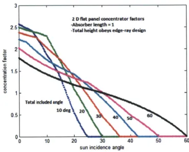
Analysis of a flat panel concentrator was led by Daniel Bridgers, a graduate student in PERG. Bridgers built a Matlab model to characterize a two-dimensional flat panel reflector trough. Figure 2-5 shows the concentration ratio of a flat panel trough for different acceptance angles. In addition, Bridgers did studies that predict the efficiency of the system based on number of position adjustments and different aspect ratios (Figure 2-6). In summary, flat panel concentrators have low tracking requirements but can only achieve low concentration ratios.
X1C
2 D flat panel concentrator factors
2.5 -Absorber laigth=1
-Total beight obeys edge-rav design
2
1.-TOWa hndued widle
0.5- 10dee 20
01
0 10 20 30 40 50 60
sun incidence angle
Figure 2-5: Concentration ratio of 2D flat panel trough for different acceptance angles.
Total effeciency as a function of adjustments and aspect ratio for 30deg concentrator
0.28
2 . ... .-.. . ...
.... .. .. -- -- 2
'D 0.
0.2
number of adjustment s aspect ratio (total height/total width)
Figure 2-6: Efficiency of 2D flat panel trough, with 30* acceptance angle, as function of
trough aspect ratio and the number of adjustments required to maximize energy collection during a day.
2.4.3 Parabolic Trough
Bridgers also took the lead in the analysis of a parabolic concentrator. Logically, the profile of a parabolic concentrator is a parabola, meaning that all incident rays of light parallel to the parabola's axis will be reflected towards the focus. Because of this, parabolic concentrators are usually used in trough designs where a cylindrical collector placed concentrically to the two-dimensional parabola's focus. This characteristic means that high concentration ratios may be obtained with this design as long as the axis of the parabola is aligned with the sun (see Figure
2-7). However, any small deviation in incidence angle causes the reflected rays to miss the focal
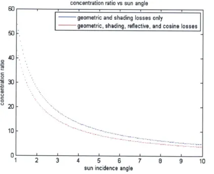
point, which requires the parabolic concentrator track the sun's position closely. Additionally, Bridgers made a model to analyze the behavior of the parabolic trough's efficiency for different incidence angles of the sunlight and trough aspect ratios (see Figure 2-8).
concentration ratio vs sun angle
60 1_1_ 1 _ 1 _ 1
geometric and shading losses only
geometric, shading, reflective, and cosine losses
40-0 30 -CD C 0 20-... 0 I I I 1 2 3 4 5 6 7 8 9 10
sun incidence angle
Figure 2-7: Concentration ratio as a function of incidence angle for parabolic trough with tube collector along focus.
Total efficiency as a function of son angle and absorber/aperture ratio
0
al
Sunlight incidence angle Absorber/aperture ratio
Figure 2-8: Efficiency of parabolic trough as a function of solar incidence angle and
absorber/aperture aspect ratio.
2.4.4 Compound Parabolic Concentrator
The compound parabolic concentrator (CPC) is an example of a non-imaging concentrator, meaning that all the light rays captured are reflected onto a region rather than focused on a point. Figure 2-9 shows the two-dimensional theoretical shape of the CPC:
Axis of CPC
\do
Axjs 01 Ams of
pwrabApa waol A A.*\A /Plabola 8
/ Aiio
Parabola Parabola
B AV
TnrnAted portion runcated portion
of parabola A of parabola 8
Focusof Focusof
parabola A (,) parabola 8 (Fo)
-Rueaver opening
Figure 2-9: Two-dimensional profile of a compound parabolic concentrator (CPC) [1].
As shown, the profile of the CPC consists of mirror segments of two parabolas, Parabola A on the right and Parabola B on the left, with different focal points, FA and FB, respectively; the focus of each branch is at the point where the opposite branch meets the receiver, labeled
Receiver opening in the figure. The height of the theoretical CPC is also defined; the branch of
each parabola extends between the Receiver opening and the point at which the slope of the curve is parallel to Axis of CPC.
By definition, the axis of each parabola passes through its focal point. The angle the axes
of the parabolas make with the axis of the CPC, labeled Axis of CPC, defines the acceptance angle, eaccept, of the concentrator. The acceptance angle defines the maximum incidence angle at which light entering the aperture will reach the receiver. If the incidence angle of the light is smaller than half the acceptance angle, light will be reflected through the receiver (see Figure
2-10a). Otherwise, the ray of light will reflect its way out through the aperture of the concentrator (see Figure 2-10b).
e, < /2 9arptv
\
/
\/
(b) BE >1/2 ae
\/
Figure 2-10: Reflection of light within a CPC -(a) incidence angle less than half-acceptance angle; (b) incidence angle greater than half-acceptance angle (from Chapter 9 of [1]).
Due to the reflective symmetry about the axis of the CPC, a different convention was used from this point forward in order to define the CPC parameters using half of the profile; Table 1 summarizes the relationship between the two naming conventions.
Table 1: Thesis notation of CPC design parameters as compared to [1].
To fully constrain the design of a CPC, only two of the three dimensions from Table 1 have to be defined because they are related by
b
a = Sinl-a Equation 2-10
Also, these parameters define the concentrator's height, H, as
H = (a + b) cot 6a. Equation 2-11
Once fully defined, the profile shown in Figure 2-9 may be used to design a two-dimensional or three-dimensional CPC; the 2D CPC is obtained by extruding the profile along the length of a trough, while the 3D CPC is obtained by revolving the profile around the concentrator's axis. The concentration ratios are described by
C R2D
sin 8a' Equation 2-12
and
3D = (s in )21 Equation 2-13
for the 2D and 3D configurations, respectively.
Figure 2-11 shows a plot of the concentration ratio that can be obtained by the 2D CPC depending on the chosen acceptance half-angle. As seen, moderate concentration ratios may be obtained with a CPC design, higher than flat panel reflectors but lower than a parabolic trough or Fresnel lens. As a general principle: the smaller the acceptance angle, the more closely the sun must be tracked. Compared to the other concentrators, the CPC provides a compromise between low tracking requirements and moderate concentration ratio. A drawback of the CPC design is its high aspect ratio (height:aperture) required to follow the theoretical geometry. However, it has
performance [6]; thus, the height of the concentrator can be reduced without dramatic decreases in the concentration ratio.
2-D CPC: Concentration Ratio 12 L L 10 8- 4- 2-0 r r 5 10 15 20 25 30 35 40
Acceptance Half-Angle (deg)
Figure 2-11: Theoretical concentration ratio of the 2D CPC.
2.5 Prior Art
As Chapter 3 will outline, the proposed solution to the problem statement was an inflatable 3D compound parabolic concentrator. In order to maximize efficacy of the design process, different existing technologies related to the concept of interest were researched. One such device was an inflatable solar collection balloon, patented by the company Cool Earth Solar, which is currently being developed as a solar energy collection device (see Figure 2-12). The balloon is made of a clear top film and a reflective bottom film; both assume the shape of a spherical dish when the structure is inflated. Sunlight enters the balloon through the top film and is reflected off of the bottom film into its focal point where a photovoltaic receiver is located for collection of the reflected light.
PV recdlww
Figure 2-12: Cool Earth Solar's inflatable solar balloon concept [7].
The patent for inflatable solar balloon [8] was used to learn about the details regarding the fabrication and operation of the proposed device. The device was designed such the films could be bonded into a flat stack assembly. In addition, it allows for the addition of features and materials to help reinforce the structure: external circumferential harness, film attachments to reduce stress concentrations and modify inflated shape, and a support from a truss-like structure.
The citations made by this patent, as well as the most recent inventions that have reference the inflatable solar balloon, were used as baseline to conduct an extensive search that captured the development of portable and inflatable radiation reflection systems over time. The patents studied were grouped into two basic categories: inflatable reflectors and solar energy collection systems. Most of the patents, regardless of the intended application, describe a similar concept that uses two flexible membranes, one transparent and another reflective, bound around their edges to create a space that is pressurized to give shape to the structure. The following
sections will highlight some of the patents that are representative of the most common design and manufacturing processes for inflatable, solar collection devices.
2.4.1 Inflatable Reflectors
[9] describes a process using pressurized fluid to shape a reflective surface, something
that has been replicated by multiple inventors. Two circular sheets of a pliant resilient plastic, one transparent and another coated with a reflecting metal, are attached around their circumference. The empty space between the sheets is filled with pressurized air, which imparts a curvature on the sheets. Figure 2-13 shows two images extracted from [9].
Figure 2-13: Images of a patent for an inflatable curved mirror [9].
In [10], an inflatable mirror that may be formed into a permanently rigid structure is described. This invention was designed for outer space; a mirror structure capable of being assembled in space and used to concentrate solar energy to several collectors. Similar to the previous patent, a mirror lens is attached to an outer ring and upon inflation it assumes a parabolic shape (see Figure 2-14a). The differences are: (1) the outer ring is also an inflatable and may be filled with a liquid material that solidifies to give rigidity, and (2) the inflation
chamber is provided by a construction element that is removed after the mirror has been shaped (see Figure 2-14b). This is possible because the mirror lens is formed by a double wall membrane that is filled with the same solidifying liquid material used in the outer ring, which fixes the mirror into a parabolic shape after inflation. Unlike the previous patent, sun radiation enters directly to the reflector instead of going through an inflation chamber.
(a) (b)
Figure 2-14: Images of patent describing inflatable mirror structure capable of being permanently formed into a rigid structure [10].
2.4.2 Collection of Solar Energy
[11] discusses an inflatable solar collector that also uses the concept of an upper
transparent flexible film and a lower sheet coated with a reflective metal which form a space in between to be inflated by a pressurized fluid. Tubes carrying a working fluid are placed inside the enclosure such that the solar rays reflected by the lower sheet are concentrated on them.
Chapter 3: Design Concept Generation
3.1 Strategies
In order to build a light-weight, portable compound parabolic concentrator, a wide variety of products in the market that contain these qualities were examined, some of which were inspiring during the design generation and brainstorming process. The main design strategies considered were foldable, collapsible, and inflatable structures.
The inspiration for the foldable or collapsible structure came from common kitchenware. Recently, products in this industry are being designed to save up space in the kitchen when they are not being used. Two examples of these are a foldable (Figure 3-1) and collapsible (Figure
3-2) colander.
Figure 3-2: Collapsible colander in both of its configurations [13].
Both of these products are designed to minimize the amount of space needed for storage, while allowing for the same functionality as their non-foldable/non-collapsible counterparts. This feature is particularly desirable for traveling equipment; one example is a metallic collapsible cup, as shown in Figure 3-3.
Figure 3-3: Collapsible cup [14].
The third strategy was an inflatable structure. Inflatable structures bring to mind images of air mattresses and bouncy houses, but are actually quite versatile. In general, inflatables are
used for equipment that must be easily transported and fairly easy to assemble when it must be used.
Comparing the three strategies, they all provide a certain level of portability but vary in weight depending on the type of material. Other differences include their footprint and volume when in their stored configuration and the number of moving parts. Both colanders are manufactured in one part and the ability to fold and collapse is added in by incorporating recesses into the design. In contrast, the cup in Figure 3-3 shows a collapsible structure with multiple moving parts. Additionally, the manufacturing process for inflatables consists of connecting different fabrics in predetermined patters. Once assembled, the procedure to make and inflatable ready for use is relatively more complex than the other strategies because it will most likely require a pump to inflate in a timely manner.
Considering all strategies and their ability to meet the functional requirements, the inflatable structure was chosen. The main reason for this decision was that the footprint of the foldable and collapsible structures during their stored configuration is constrained by their ready-for-use dimensions. Inflatable structures have considerably less volume when stored than during their fully inflated states due to the lack of pressurized air, allowing the inflatable to be stored in a more compact manner. Furthermore, the idea of an inflatable solar concentrator is highly creative, innovative, and worth exploring.
3.2 Concept Selection
The extensive search for prior work on inflatable concentrator technology, detailed in Section 2.4, led to development of two design concepts: enclosed (Figure 3-4a) and open (Figure 3-4b).
(a) (b)
Figure 3-4: Design concepts for inflatable solar concentrator - (a) enclosed envelope and (b)
open, inflatable frame.
The first concept consists of attaching elastic membranes along their edges to enclose an envelope that may be inflated with a pressurized fluid. Figure 3-4a is a representation of a three-dimensional CPC that could be made with the combination of two types of elastic membranes, one transparent and the other reflective, of varying thicknesses such that a desired non-spherical shape may be obtained. The top membrane would be transparent to allow the sunlight to enter the concentrator, while the bottom membrane would have to be reflective on the inside to direct entering sunlight towards the concentrator's exit. The sides of the reflector would be made of a
reflective flexible membrane or a plastic with a coat of reflective material on its inside. Additionally, the walls may be encased by an external plastic sheet to provide rigidity. Once the membranes are sealed around their edges and the gap between has been them pressurized, the concentrator would be placed on top of a collector.
The advantage of the enclosed concept is that the reflective surface is completely sealed off from the environment. Consequently, no dirt or dust can accumulate on the reflective surface which may decrease the optical efficiency of the system. Another advantage is that the manufacturing process will be fairly simple, only requiring the sheets of material to be joined together. One of the biggest drawbacks of this concept is that it requires light to be refracted through the transparent membrane in order to enter the concentrator. As detailed in Section 2.3, when rays of light are refracted, a fraction of the ray is reflected and energy is lost. In addition, having the reflective region closed off would make it difficult to access in the future for maintenance or repairs.
The idea behind the second concept is to leave the structure open to the environment and eliminate the need for sunlight to be refracted into the concentrator. As shown in Figure 3-4b, this concept consists of creating inflatable ribs and support rings to provide a rigid structure for the concentrator. By allowing light to enter the aperture directly without going through a transparent membrane, reflective losses are eliminated and a higher amount of solar energy is captured. This concept requires the manufacturing of independent reflective segments, which may be vacuum formed, to be attached to the ribs filling up the space between them. These segments may be made from a naturally reflective material or from some other material that is well-suited for the selected manufacturing process, and is later coated with a reflective film.
An advantage of the open frame concept is that it does not require the structure to be inflated exclusively with air, and as such the fluid won't be in the sunlight's path. There are existing products that provide the ability to inflate a structure with a fluid that solidifies with time (e.g., expanding foam), providing a rigid structure once inflated. This may not be ideal if the user wants to deflate the concentrator after some period of time, but it is still a possibility. Since the reflective surfaces are exposed to the environment, they are easy to access if needed for any repairs, maintenance, or modifications; but this means that it will also be exposed to dust, dirt and other particles that will deteriorate the optical efficiency of the system. From a manufacturing standpoint, building and assembling this inflatable model would be more complex given that the reflective surfaces must be made separately and incorporated into the rib structure.
During the concept evaluation process, Otherlab was contacted for consultation. Otherlab is a private research and development company based in San Francisco, CA, with experience in the design and manufacturing of inflatables consisting of complex geometries. Both concepts were run through Otherlab, and their input was taken into account given their expertise. They expressed concern regarding the closed concept because of its dependence on the ability of the transparent plastic membrane to refract light into the system. Otherlab pointed out that ultraviolet light emitted by the sun deteriorates plastics. To prevent this, it could be treated with the cost of jeopardizing its transparency, which would amplify reflective losses and eliminate the efficiency of the system. After careful consideration, it was decided to move forward with the open inflatable frame design and avoid these risks.
Chapter 4: Analytical Model
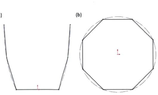
4.1 OverviewAnother consideration in an attempt to simplify the manufacture of the inflatable concentrator was making reflective facets out of straight sections, rather than a parabolic curved wall as suggested by the theoretical CPC design (Figure 4-la). From a manufacturing standpoint, it is simpler and cheaper to work with flat sections than having to go through the necessary processes to form materials into a specific shape permanently. In addition, using straight sections along the height of the concentrator connected to the inflatable ribs means that the shape of the top-view cross-section will no longer be a circle, as it would be in the theoretical 3D CPC. Instead, the cross-sectional shape with be a polygon, where the number of inflatable ribs defines the number of sides in the polygon (Figure 4-1b).
(a)
WL
Figure 4-1: CPC approximation using flat sections - (a) 2D profile using flat segments to approximate parabolic curve and (b) top cross-sectional view of polygon approximating circular geometry.
As seen in Figure 4-la, the parabolic-shaped wall of the CPC (dotted line) may be substituted by flat sections. Intuitively, as the number of flat segments increases, the wall geometry will more closely approximate the theoretical parabolic curve. Figure 4-1b depicts a top view of the concentrator's cross-section showing the theoretical circular geometry (dotted line) approximated by the polygon created by the ribs (corners of the polygon) and the reflective facets (sides of the polygon). This specific example shows the geometry for a design using eight ribs, thus the cross-sectional view of the aperture assumes an octagonal geometry. In this view, the same concept as in the side cross-sectional view applies, as the number of ribs increases, the number of sides in the polygon increases and the cross-sectional geometry more closely approximates a circle.
Besides the usual design parameters that must be selected for the design of a typical compound parabolic concentrator, the proposed design requires the selection of two others: the number of flat sections in each facet and the number of inflatable ribs. In order to make a sound engineering decision, the direct effect of each of these two factors on the optical efficiency must be determined. The approach was to build an analytical model of the concentrator that predicts the efficiency of the system as a function of different solar incidence angles, the number of panels and the number of ribs used. This model would then be tested with prototypes by comparing the experimental and theoretical results to understand the accuracy of the model. Having an accurate analytical model of the system is a powerful design tool because it provides the means to determine the key design parameters to meet any specific set of requirements for a given application.
4.2 Ray tracing: First-order approximation
The analytical model for this design was a ray tracing code (using Matlab) that would calculate the efficiency of the solar concentrator for different solar incidence angles as the number of flat segments and ribs were iterated. The strategy was to model a two-dimensional view of the concentrator profile and understand the behavior of an evenly distributed source of light entering the aperture. For the first-order approximation, the goal was to build a simple model that would help guide the design process. In the ray tracing program, only rays going into the collector with zero or one reflection were accounted for and only one half of the reflective profile was considered.
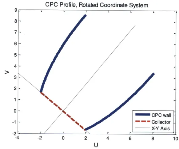
To describe the reflective surfaces of the concentrator, the explicit equations of the parabolic branches were derived. Since these are tilted parabolas, the equations were described based on a rotated coordinate system (U-V axes). Figure 4-2 shows a graphical representation of the CPC in the rotated coordinate system corresponding to the right branch of the CPC. However, all the known parameters are specified in a coordinate system where the vertical axis is aligned with the axis of the CPC (X-Y axes). Thus, a supplementary Matlab code was written to transfer points between coordinate systems.
CPC
Profile, Rotated Coordinate System
9 8 7 6 5 4 3 2 1 0 -1 -2 0 2 4 6 8 L -C r C -x-U
Figure 4-2: CPC profile in a rotated coordinate system, as seen from the right branch.
As seen in Figure 4-2, the U-V coordinate system is rotated with respect to the X-Y coordinate system about the origin by half the acceptance angle of the CPC such that the axis of the parabola is coincident with the V-axis. Given this orientation and the known dimensions of the parabola, the equation of each branch was determined.
The proposed design is based on the premise that the facets between the ribs, made of a number, n, of flat panels compose the reflective region in the concentrator. In a two-dimensional view of the model, the flat panels are seen as lines which approximate the parabolic branch of the
PC wall
ollector -Y Axis
10
the collector and aperture was divided into n intervals; the lines connecting the endpoints between each interval represent the flat panels in the model.
The other component that had to be characterized was the incident light. The rays of light were described parametrically using the points of entry along the aperture and the angle of incidence. To ensure an even distribution of incident light, the points of entry were obtained by using the endpoints of equal intervals along the length of the aperture.
Using the equations for the light rays, reflective segments, and the collector, the intent of the Matlab code was to utilize a curve intersection script to determine where each ray of light intercepts the concentrator, whether it goes directly to the collector or undergoes a reflection. If the ray intersects one of the reflective segments, the code uses Equation 2-2 to compute the equation of the reflected ray.
4.2.1 Number of Reflective Panels
The first analytical model was used to understand the effect that the number of reflective panels used in each facet has on the optical efficiency of the concentrator for different angles of incidence. It is important to note that this model ignored the varying size of the collector depending on the number of inflatable ribs used; it was assumed that the size of the collector is constant and covers the entire distance across the two-dimensional side cross-sectional view. In the Matlab ray tracing code, loops were used to iterate through different angles of incidence for the rays of light and different number of reflective panels along the wall of the concentrator. Below is a plot showing how the first-order ray tracing program works:
Ray Tracing: Incidence Angle = 30 deg
-4 -2 0 2 4
U-axis
6 8 10 12
Figure 4-3: First-order ray tracing analysis for varying number of panels; incidence angle of
300 entering concentrator profile containing three reflective panels along walls
Figure 4-3 is a graphical representation of the first-order ray tracing model used to capture the effect of using different number of reflective panels in each facet; the other branch seen in the cross-section is only shown to provide perspective of the geometry of profile. As mentioned, the reflective panels along this other branch were ignored in this first-order model. This particular example depicts a scenario of five rays of light at an incidence angle of 30* entering the aperture of a concentrator with three panels along its reflective walls. From the five evenly distributed incident rays (red), two reach the collector (dotted blue line) directly and the other three are reflected (green) off of the panels (solid blue) at different points along the length
.ts 10 8 6 4 2 0 -2 Collector Panels Incident Rays Reflected Rays r r Ir r
-explain why all three reflected rays have different orientations. In this specific scenario, all incident rays reach the collector with at most one reflection. However, two of the limitations of this first-order model are that if rays were to reach the other branch of the profile a reflection wouldn't be recorded, and if the rays were theoretically going to bounce off a second reflective panel and still reach the collector, it would be considered a loss in the efficiency calculation.
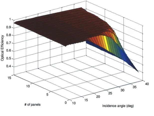
To fully capture the effects of solar incidence angle and number of reflective segments on the optical efficiency, the ray tracing code sweeps through different scenarios and calculates the optical efficiency for each one. The results were plotted in a three-dimensional surface graph:
0.9 0.8, Q 0.7 .6 0.5, 01 0.4, 15 10 35 4 5 25 30 5 20 2
# of panels 0 10 Incidence angle (deg)
Figure 4-4: First-order ray tracing model results - optical efficiency as a function of incidence angle and number of reflective segments. (Acceptance half-angle: 40*)
The first observation made from Figure 4-4 was that, as expected, efficiency increases as incidence angle approaches 0* (perfectly aligned with the axis of the concentrator), and as the number of panels increases (reflective wall geometry gets closer to the theoretical parabolic shape of the CPC). However, it was observed that increasing the number of panels used to approximate the parabolic branch had diminishing returns in optical efficiency. For small incidence angles there is practically no benefit in using high number of panels, but at larger incidence angles, still within the acceptance angle of the design, there is. Figure 4-5 is an alternate view of Figure 4-4 that shows the optical efficiency dependency on the number of panels for lager angles of incidence:
W 0 0.7-0.6 0.4 0 5 10 15 # of panels
The view in Figure 4-5 depicts the effect of the number of panels on optical efficiency more clearly; it shows the region corresponding to larger incidence angles. As the incidence angles decrease (higher curves in the plot), overall efficiency increases and the point of marginal diminishing returns for number of panels is reached with smaller number of panels. In other words, the maximum efficiency of the system with a parabolic wall (equivalent to an infinite number of panels) can be approximated fairly closely by using a small number of panels. For example, in the model of this concentrator with an acceptance half-angle of 400, at an incidence angle of 300, the maximum optical efficiency with fifteen reflective panels, 94.65%, can be obtained with just four panels.
4.2.2 Number of ribs
Changing the number of inflatable ribs in the design effectively changes the size of the collector by changing the number of sides on the polygon-shaped cross-section as seen from a top view. As the number of ribs increases, the cross-section more closely approximates circle which is the theoretical shape of the three dimensional CPC. This relationship is graphically demonstrated in Figure 4-6:
1 77 -- L
Figure 4-6: Top view of concentrator cross-section showing relationship between larger number of polygon sides and larger apothem.
Figure 4-6 shows polygons inscribed in circles of the same diameter with the distance of the apothem, which is the distance between the center (concentrator axis) and the side (reflective panels) of the polygon. As expected, the length of the apothem increases for polygons with a higher number of sides.
To analyze the effect of the number of ribs on the optical efficiency of the concentrator, the previous model was modified slightly to produce two new models. Firstly, a model was built where the number of panels in each facet was fixed and the optical efficiency was calculated for different incidence angles and number of ribs. Secondly, the optical efficiency dependency on the number of panels and the number of ribs was calculated for a given incidence. Below is a graphical representation of first-order ray tracing analysis done to analyze the effect of changing the number of ribs in the design:
Incidence Angle = 30 deg; # of Panels = 3; # of Ribs: 5 L-L
H
r r -4 -2 0 2 4 U-axis 10 8 6 6 8 10 12Figure 4-7: First-order ray tracing analysis for varying number of ribs; incidence angle of
300 entering concentrator profile containing three reflective panels along walls and five ribs.
Figure 4-7 shows the ray tracing model of five rays with incidence angle of 30* entering a concentrator with acceptance half-angle of 40' and five ribs when it has three reflective panels along its height. Again, the results were plotted in a three-dimensional surface graph for both scenarios: fixed number of panels (see Figure 4-8) and a fixed incidence angle (see Figure 4-9).
-W 4 2 0 -2 --- Collector Incident Rays Panels Reflected Rays
-/
Numberof Panels: 10 1 0.81 -0.6, -a 0. 4-A2 0 40 30 15 20 10 5
Incidence Angle 10 0 Number of ribs
Figure 4-8: First-order ray tracing model results - optical efficiency as a function of number incidence angle and number of ribs for a fixed number of panels. (Acceptance half-angle:
400)
Incidence Angle = 20deg
0.95 S o.9, S0.85-w -g0.8, O0. 75 0.7 -10 15 10 5 5
As seen in Figure 4-8, similar to what was observed in Figure 4-4, increasing the number of ribs has diminishing returns in optical efficiency for a specific range of incidence angle; the effect becomes more noticeable at the extremes, close to 0* and close to the acceptance half-angle. Figure 4-9 reveals that for a fixed incidence angle, the number of ribs is the most influential factor on the optical efficiency. It can be assumed that this relationship varies depending on the incidence angle; but given the right conditions, the design of a CPC could be simplified dramatically. In conclusion, it was also determined that the maximum efficiency of the system with the theoretical CPC geometry can be closely approximated by a small number of ribs.
4.3 Ray Tracing: Multiple Reflections
During the testing phase (Chapter 6), a more accurate analytical model was built, which considered multiple reflection, including the other reflective branch of the concentrator profile. The same procedure was done to determine the equations of the straight segments along the other branch. However, since the second branch is aligned on another coordinate system, all the points and equations had to be transformed to the same U-V coordinate system that was being used. In addition, an extra loop was added to the code which considered rays that required multiple reflections to reach the receiver. The new model provided more accurate values of efficiency for specific design parameters, but it the same trends were observed.


![Figure 2-14: Images of patent describing inflatable mirror structure capable of being permanently formed into a rigid structure [10].](https://thumb-eu.123doks.com/thumbv2/123doknet/14687533.560490/36.918.151.759.349.529/figure-images-describing-inflatable-structure-capable-permanently-structure.webp)