Design and Fabrication of Pressure-Compensating Compliant Tubes
by
Ian Martin
Submitted to the
Department of Mechanical Engineering
in Partial Fulfillment of the Requirements for the Degree of Bachelor of Science in Mechanical Engineering
at the
Massachusetts Institute of Technology
June 2014
MASSACHUSETTS INSTITUTE
OF TECHNOLOGY
JUL 3
0
2014
LIBRARIES
02014 Massachusetts Institute of Technology. All rights reserved.Signature of Author....,
Certified by ...
Signature redacted
Department of Mechanical Engineering May 9, 2014
Signature redacted
Signature
Accepted by ...Amos G. Winter V Noyc Care.evelopment Assistant Professor
redacted
Thesis Supervisor
Anette Rosoi ...
Design and Fabrication of Pressure-Compensating Compliant Tubes
by
Ian Martin
Submitted to the Department of Mechanical Engineering on May 9, 2014 in Partial Fulfillment of the
Requirements for the Degree of
Bachelor of Science in Mechanical Engineering
ABSTRACT
Different fabrication methods are evaluated for producing pressure-compensating tubes for use in low-pressure drip irrigation systems. Such devices would allow drip irrigation systems to operate at driving pressures much lower than those required by current available technology, allowing for cost and water savings in developing nations. Fabrication methods explored consist mainly of molding of liquid silicone rubber and production from existing silicone stock by folding or binding multiple sheets of material together. Based on small-scale production and testing, the sheet fabrication method
showed some promise of equaling the performance of the injection-molded tubes, but both methods require further refinement going forward.
Thesis Supervisor: Amos G. Winter, V
TABLE OF CONTENTS
ABSTRACT 3
TABLE OF CONTENTS 4
LIST OF FIGURES 5
INTRODUCTION 6
PRESSURE COMPENSATION USING THIN-WALLED TUBES 7
TUBE FABRICATION TECHNIQUES 9 EVALUATION OF TUBE FABRICATION TECHNIQUES 14
TUBE TESTING PROCEDURE 15 EVALUATION OF TUBE PERFORMANCE 16
CONCLUSIONS 20
LIST OF FIGURES
Figure 1: Figure 2: Figure 3: Figure 4: Figure 5: Figure 6: Figure 7: Figure 8: Figure 9: Figure 10: Figure 11: Figure 12: Figure 13: Figure 14: Figure 15: Figure 16: Figure 17:Dimensionless law of tube collapse
One dimensional approximation of fluid flow Compliant tube coupled to a rigid diffuser Coated tube before and after removal Molded tubes curing
Comparison of molded tubes
Cross-section of sheet-formed tube geometries First run of sheet-formed tubes
Clamping setup for rod-clamped eye-shaped tubes Sheet-based eye-shaped tubes, rod clamping method
Plate-clamping setup Overview of testing setup
Flow regimes of PC tube during testing Clamped tube used for testing
Overview of data taken during testing Two tubes with induced collapse
Shore A 35 tube with and without induced collapse
7 8 8 10 10 11 11 12 12 13 13 16 17 17 18 19 19
INTRODUCTION
With continued increases in global population, both food and water resources are being drawn thin in many areas of the world. With the prospect of shortages in mind, there is a need to find ways of increasing food production while using less water-intensive
processes. Currently, many farmers in countries such as India follow the practice of flood irrigation, which consists of simply diverting large amounts of water into fields. While simple and low-cost, this practice is very water intensive and poses a significant threat of water scarcity in a country where overall water use is projected to increase almost two almost double 1985 levels by 2025 while per capita water availability decreases by over 25% over the same period [1].
At the moment, less water-intensive alternatives to flood irrigation do exist, however high capital costs often hinder implementation by subsistence farmers in developing countries. One such example is drip irrigation, which consists of water being pumped through a series of tubes to emitters that control water flow to plants. Though such systems have found acceptance in the agricultural community at large [1], there has been difficulty implementing them with subsistence farmers, who often cannot bear the capital and energy costs required to produce the high driving pressures required by today's systems. This investment in pumping infrastructure and energy puts most current off-grid systems in the cost range of several thousand dollars per acre. By contrast, most
subsistence farmers, who often farm only one or two acres, would only be able to afford a drip irrigation system if it's cost was less than $300/acre [2]. Additionally, since drip irrigation systems would increase yields and decrease water scarcity in impoverished areas, making such systems affordable for subsistence farmers has a strong potential for significant quality of life gains.
The easiest way to reduce the cost of a drip system is to lower the pumping pressure to decrease the pump size and energy requirements, which make up a significant fraction of the system cost. However, decreasing the driving pressure to the range of 0.1-0.3 bar requires the use of pressure-compensating (PC) emitters to balance viscous losses in the piping system. PC emitters passively deliver a steady flow rate regardless of pumping pressure by constraining high-pressure flow and allowing low-pressure flow to proceed unimpeded.
PC emitters are currently commercially available, however none of the current designs meet the cost and flow requirements of the desired system. In order to fulfill the requirements of subsistence farmers, the emitters must have a unit cost lower than $0.025 and be capable of activating at pressures of 0.1-0.3bar to produce steady flow rates in the range of 3-20 liters/hour [2]. Recent work on low-cost PC emitters [2,3] has introduced a new technique that mimics the pressure-compensating ability of thin-walled tubes in a biological setting. The compensating effect of a compliant tube, which is a common
biological method of pressure regulation, has been modeled and shown to demonstrate the behavior desired of a low-cost PC emitter when paired with a rigid diffuser [2].
This paper seeks to build on this prior work by investigating methods of producing thin-walled compliant tubes on both a laboratory and high-volume scale. Prior attempts at manufacturing consisted primarily of molding and coating processes using liquid silicone rubber. In addition to introducing new optimizations to these existing processes, new techniques such as production from stock silicone sheets were investigated and evaluated
on the criteria of production rate, flexibility, and consistency. Testing was also done to begin an empirical characterization the effect of tube length, diameter, and shape on the tubes' pressure-compensating ability.
PRESSURE COMPENSATION USING THIN-WALLED TUBES
The pressure-compensating effect of collapsible tubes was modeled by Ascher Shapiro [4] and has been demonstrated more recently to provide a viable low-cost alternative for PC emitter design [2,3]. Following previous work, the ability of compliant tubes to provide effective pressure compensation derives from the collapse of the tube when the transmural pressure is negative and the external pressure exceeds that of the
internal fluid flow. In this regime the pressure differential causes the tube to collapse, forming a nozzle-diffuser pairing that pressurized the internal flow until it can equal that of the external pressure force [3]. This behavior can be observed in Figure 1.
0
-10
-20
-AP
K
0.5
1k,00
-""'""O
Effective
sti
is given by
A/A
0
ffness
slope
Figure 1: Tube collapse in the regime of negative transmural pressure, taken from [2]. A/Ao refers to the collapsed tube cross-sectional area relative to the initial cross-sectional area, K, is a constant pertaining to the elastic properties of the tube, and AP is the transmural pressure difference. Note that once the transmural pressure becomes negative, tube
collapse proceeds rapidly toward complete constriction.
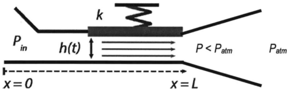
Further investigation [2] explored the conditions required for tube collapse. In this model, the tube is represented one-dimensionally and the collapse effect is represented as a plate attached to a spring controlling the "height" of the stream (see figure 2).
P.
In
h(t)
P
atm
x=0 x=L
Figure 2: One-dimensional approximation of fluid flow in a collapsible tube with the
collapse effect represented by the plate and spring of constant k, taken from [2].
The fluid density, p, the stream velocity, Vo, the out of plane area of the plate, Ap, the spring constant, k, and the initial "height" of the fluid stream, ho, can be combined into a resultant dimensionless quantity governing the response of a compliant tube to a small
one-dimensional perturbation in flow area [2], shown below:
pV 2Ap
Ccoapse = khoA(1)
When the pressure forces exceed the restorative forces, the tube collapses.
However, when applied to an unconstrained tube this will result in resonant behavior that would present issues of mechanical fatigue in engineering applications [2]. This is resolved
by the addition of a rigid diffuser to the end of the PC tube (see figure 3), which causes the transmural pressure at the downstream end of the tube to become negative without
causing the tube to enter an unstable resonance [2]. This system provides an ideal scheme for pressure compensation given that it consists of two relatively simple parts.
Additionally, it provides clog resistance because a stop in flow will result in full expansion of the tube and thus the ejection of the blockage [2].
in___h__W P < Patm Patm
x=0
x=L
Figure 3: Compliant tube with a rigid diffuser added to the right-hand (downstream) end. The diffuser forces the transmural pressure to be negative at the diffuser inlet and thus initiates partial tube collapse.
TUBE FABRICATION TECHNIQUES
Currently, silicone tubing is commercially manufactured, often for use in the medical device and pharmaceuticals industry. Production techniques consist primarily of molding and extrusion. Molding often offers tighter tolerances than extrusion and is usually performed with liquid silicone rubber (LSR), which is mixed from part 'A' and 'B'
components immediately before injection. Extrusion offers lower costs than molding and does not limit the length of the tube. Extrusion typically is done with a different variety of silicone called high consistency rubber (HCR), which is initially putty-like and is cured by heat treatment following extrusion [5].
For the purposes of this investigation, small-scale injection molding using LSR and production from silicone sheets were the primary modes of fabrication on the lab scale. Additionally, a coating process was attempted with LSR, though this proved less successful than the molding approach.
Fabrication from Liquid Silicone Rubber: Injection Molding and Dip Coating
Initial attempts to produce PC emitter tubes focused on scaled-down versions of high-volume processes such as coating and injection molding. Both of these processes utilized liquid silicone rubber as a feedstock. The LSR was mixed from its base and catalyst constituents and subsequently injected into a tube mold or poured over a substrate. Due to the short pot life (time from mixing to setting) of the available silicone, some modifications had to be made so that the coating and injection processes could be completed prior to the material setting.
Coating was the initial method of tube fabrication and had been attempted in prior proof-of-concept tests. Upon being mixed, the LSR would be poured over a brass rod in as even a pattern as possible, with the rod being subsequently suspended for curing. Several issues arose from this process: First, the LSR's low viscosity compared with other
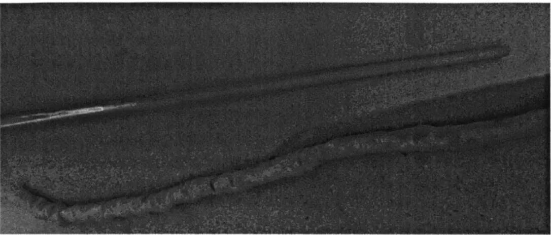
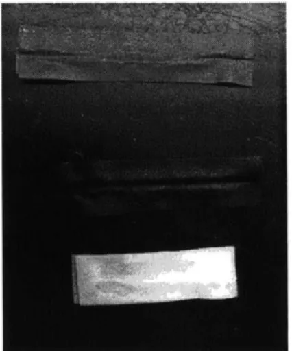
materials such as HCR resulted in a large amount of material loss from drippage during curing. Second, even coating of the brass rods was difficult to achieve and thus tube wall thickness varied circumferentially. Third, the ten-minute pot life combined with the low viscosity of the LSR resulted in excess accumulation toward the bottom of the hung rods and little to no accumulation toward the top. This resulted in thickness varying along the tube length. Finally, when removed from the rods, the tubes became very wrinkled and did not return to a smooth state following removal (see figure 4). The combination of these factors led to tubes with very little dimensional consistency, which is necessary for proper PC emitter performance.
Figure 4: Coated tube before (top) and after (bottom) removal from brass rod. Note extensive wrinkling and tearing in the tube post-removal.
Given the low success rate of the coating process, a small-scale injection molding process was subsequently investigated. Molds were constructed from brass tubes of varying inner diameters (mold cavities) and brass rods of varying outer diameters (mold cores). End caps machined from aluminum round stock fixed the location of the cores to be concentric within the cavities. The most successful iteration of the production process involved injecting mixed LSR into an upright mold cavity through the lower end cap. Thus, as silicone entered the cavity air bubbles would be pushed out the top of the tube instead of being trapped in the curing rubber. Once the cavity was full, the core would be pushed through and the other end cap added.
Figure 5: Cast tubes curing upright. Three different core sizes can be seen protruding from the upper end cap.
Molding provided the most dimensionally consistent tubes of any of the processes tested, however it was not without issues. The lack of any kind of draft angle on the mold
cavities often resulted in difficulty in removing the cured tubes, which subsequently resulted in damage to the tubes and/or the destruction of the mold. Attempts were made to resolve this by coating the interior of the cavity with a brush that had been sprayed with
mold release agent. While this seemed to provide some aid in cavity removal, improvement was not consistent enough to trace it to this source.
In addition to removal issues, the inclusion of air bubbles was a persistent issue throughout fabrication trials. As previously stated, efforts were made to conduct the injection process such that air bubbles in the cavity were minimized, but air bubbles formed in the mixing process along with those resulting from interaction between the silicone and particulate within the mold were still problematic. Additionally, castings were allowed to cure in an upright position, encouraging air bubbles to propagate toward the "top" of the tube and thus isolating the low-quality air-bubbled silicone from the desired solid silicone at the "bottom" of the tube. Use of a silicone with a longer pot life could allow for vacuum casting or at least allow air bubbles more time to propagate toward one end of the tube.
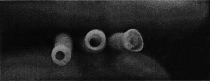
Figure 6: Three cast silicone tubes. Left to right: 4mm OD, 1.5mm ID; 4mm OD, 2mm ID; and a 1.5mm ID tube with extensive air bubbling. Note the thickness variation. This is likely a result of the core shifting as a result of the tubes not being cured completely upright (they were leaned against a vertical surface) and the end caps having loose enough tolerances to allow core-cavity shifting.
Fabrication from Silicone Sheets
In addition to the fabrication methods focusing on forming liquid silicone rubber, several attempts were made to fabricate tubes by joining stock silicone sheets. Rather than forming a perfect annulus, a silicone sheet was either folded back on itself to give a
teardrop-shaped duct or sealed to another sheet along two edges to form an eye-shaped duct. Since silicone rubber is a thermoset elastomer, heat sealing was not an option and thus a Dow-Corning 732 adhesive was used for joining the sheets together.
Figure 7: Cross-sectional views of the eye-shaped (left) and teardrop-shaped (right) sheet-based tube geometries.
eye-shaped tubes were being made. However, this method presented several issues. While the Dow 732 adhesive was very efficient at bonding the silicone sheets together, it was also very efficient at bonding the sheets to the brass rod, making removal difficult. Additionally, this setup placed the inner glue edge in an unconstrained location, thus the inner edge of the glue bead varied greatly in radial position along the length of the tube. By definition this resulted in a large variance in effective diameter along the length of the tube and thus was deemed unsatisfactory based on its lack of consistency.
Figure 8: First run of sheet formed tubes. Note significant variation in the inner glue edge, which determines the channel size. In this run, rods with 1, 2, and 3mm outer diameters were used for fixturing. The grey, black, and white sheets have Shore A hardnesses of 10, 20, and 35 respectively.
A secondary method of producing tubes from silicone sheets consisted of clamping off the desired tube channel area. For eye-shaped tubes, this consisted of clamping two brass rods along the central axis of a pair of silicone sheets, whereas for teardrop tubes the brass rods were clamped with the sheet fold on one side and the flaps to be glued on the
other. This method provided an advantage over wrapping the sheets around the rods in that the inner glue edge was now along the clamped rods, providing for a much more
consistent glue bead along the length of the tube. This worked very well for the teardrop shaped tubes and produced results that could compare with defect-free molded tubes in terms of dimensional consistency. However, the eye-shaped tubes ended up having very small channels as a result of the small contact area between the brass rods. Additionally, while the teardrop tubes' channels could be kept open by adjusting the sheet position
during setup, the eye-shaped tubes' channels were very difficult to open since the tubes had been formed with the channel as a pinch point
Figure 9: Clamping fixture for eye-shaped sheet tubes. The two rods preserve a central channel, leaving the loose edges accessible for gluing and providing a steady glue line along the channel edge.
Figure 10: Eye-shaped tubes produced by rod-clamping fixture (see figure 8). Note pinched central channel. Shore A hardnesses range from 10-35, top to bottom. Note tearing on the top sample.
With the success of the rod-clamped teardrop tubes, additional improvements were attempted by clamping two plates over the channel area. This was based on the difficulty with clamping the two rods together while ensuring that the fold line and clamping line were parallel (and thus the tube diameter consistent along its length). The plate method allows for the fold line to be placed a set distance from the edge of the plate, allowing a much more controlled method of determining the tube diameter. However, the plate-clamping method proved to have its own set of challenges. Silicone sheets do not crease, and thus keeping the fold line in one spot with nothing to constrain the free ends became very difficult. This resulted in the sheets having to be extensively tacked to the bottom plate with tape prior to clamping. However, the resulting tubes were of acceptable quality
EVALUATION OF TUBE FABRICATION TECHNIQUES
As discussed in the prior section, each method of PC emitter fabrication presents its own advantages and challenges. With optimization, each of the presented options could be used as a viable method for fabrication of silicone PC emitters.
Fabrication from liquid silicone rubber
Dip coating is a widely accepted commercial practice, and with improvements could likely be applied to emitter manufacturing. Many of the issues observed in small scale testing could likely be resolved by coating the substrate with a release agent (to reduce wrinkling and removal difficulty) and using a silicone with a longer pot life (to allow more time for an even circumferential coating to form). However, neither of these improvements addresses the longitudinal thickness variation that was observed in the course of these tests. Likewise, the finite pot life of liquid silicone once mixed means that a coating process would likely result in a significant amount of waste generation from leftover material being left to cure. Because most elastomers are thermosets, this waste cannot be melted and reused. Therefore, going forward it is recommended that other methods be pursued for manufacturing compliant PC emitters.
Casting/injection molding provides some promising gains with respect to
dimensional consistency and waste reduction, however it still presents issues with part removal, air bubbling, and high fixed costs for molds. While the cast tubes were most dimensionally consistent, the lack of any draft angle on the molds presents difficulty for high-volume production. Release agents and changing the mold material could help resolve this issue, however both of these solutions have the potential to raise costs. Likewise, on the laboratory scale it is very difficult to cast tubes of the proper thickness with the current injection molding system. Most of the tubes manufactured by casting over the course of this study were too thick to present collapse effects, whereas attempts to manufacture thinner-walled tubes usually resulted in the silicone disintegrating upon removal from the mold. Beyond the removal issues, the inclusion of air bubbles could be resolved with pressure casting, but this would likely require using an LSR formulation with a longer pot life in addition to lengthening cycle time on its own. Finally, the casting
process, though more efficient than coating, still produces a lot of waste that is non-recyclable. Beyond the fact that material is wasted, in volume production this waste must also be flushed from any plumbing prior to curing in order to avoid clogging production equipment. In short, while molding/casting can yield tighter tolerances than most other methods, many of the cost gains associated with high-volume injection molding are
compromised by the difficulties of working with a slow-setting material that must be mixed at the point of injection and that sets permanently.
Fabrication from joining silicone sheets
The sheet joining process offers several advantages if its consistency can be improved to match or exceed that of the molding process. Compared with the LSR processes, the sheet-joined tubes use more silicone than a LSR tube of comparable
diameter and thickness since the extra flap of silicone is required for gluing the two sheets together. However, there is far less potential for waste material such as mold overflow and drippage from a coating process. Additionally, while the glued area must be rather large on the lab scale as a result of a non-mechanized assembly process, if done in volume it is likely that the extra silicone required for a binding surface could be greatly reduced. A key
downside of the sheet process is that it requires adhesives, implying a longer cycle time. Changing to faster setting adhesives and pushing parts into a "curing" inventory could address this issue during high-volume production. Additionally, switching to a
thermoplastic elastomer could allow for heat-sealing, greatly improving throughput on this process and reducing waste on the LSR processes. Regarding dimensional consistency, improvements in fixturing and adhesive application could likely lead to improvements here and allow for more geometric flexibility such as conical tubes (discussed below).
One of the bigger advantages of the sheet-joining process is that it does not require as significant of an investment as other processes. Fixturing is required, but it is unlikely to require the degree of precision that would be required of mold cavities and cores.
Additionally, in the current state the casting process is very destructive to the molds whereas the sheet-forming process has not been shown to result in any kind of damage to the fixturing equipment. While the joining process is not a unit manufacturing process, it is possible that the cost of silicone sheets and adhesive (both relatively low-cost materials) could still be lower than the additional quantity of LSR required to account for waste in the other processes.
Another sheet-forming process investigated only briefly is to eliminate the use of adhesives altogether and to operate the emitter with the two flaps clamped rather than permanently joined together. This was done primarily to acquire usable data as a result of the cast and joined tubes failing to demonstrate significant collapse. However, it could show promise as a future production technique. In this scheme, the diffuser would be rigidly connected to the output of the piping system. A clamping mechanism could be attached to this rigid connecting beam or could comprise the rigid connection itself. The silicone sheet would then be folded, with the free edges inserted into the clamp, the upstream end connected to the pipe output, and the downstream end connected to the diffuser. This option presents several significant advantages: The
diffuser-clamp-connection unit would be more complex to manufacture, but could likely be done using a high-volume process that would shrink the added cost of this complexity. The compliant tube component could then be produced as a simple silicone sheet that would only have to be folded and inserted into the clamping mechanism. Given the difficulty encountered with this step during testing, it would definitely be an avenue for future improvement. However, it greatly simplifies the emitter production by replacing the adhesive fixturing and curing with a simple mechanical assembly. It also minimizes the use of silicone in the unit manufacturing process, shifting the complexity to a clamp assembly that can be process-and material-optimized much more effectively.
In summary, going forward the casting and sheet-joining process both show promise as methods of manufacturing PC emitters from compliant materials. While the
TUBE TESTING PROCEDURE
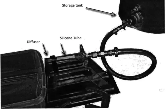
To evaluate the pressure-compensation performance of the silicone tubes, a testing setup constructed for prior work was employed. The procedure began with pumping tap water into a tank, which once full would be connected to the shop air supply and
pressurized from 0-15psi gauge. Once pressure regulation was satisfactory, a check valve could be opened, allowing the pressurized water to flow through the emitter system. This consisted of a plastic nozzle connecting the pipe to the PC tube, which was followed by a plastic diffuser to initiate tube collapse.
Figure 12: Testing setup. The storage tank can be seen upper right (pump and air supply not pictured). Center left, the diffuser, PC tube, and pipe outlet can be seen left-to-right.
Because these tests primarily functioned to develop estimates of the tubes' pressure-flow rate trends, flow rate was calculated by measuring the amount of time required to fill a beaker to 500mL. At higher flow rates, the volume of water flow over a 10 second period was measured due to difficulties resulting from the stream being near-horizontal, requiring the beaker to be angled to capture the flow.
EVALUATION OF TUBE PERFORMANCE
Unfortunately, none of the cast or joined tubes presented an autonomous collapse effect when connected to the experimental setup. In large part, this was effected by the tube collapse initiating immediately upstream of the diffuser. Upon collapse, the flow would immediately separate within the diffuser and prevent the intended pressure
recovery from occurring. Once the flow separation occurred, the pressure at the diffuser intake would revert to the ambient condition and the tube would operate in its normal steady-state behavior with minimal pressure compensation.
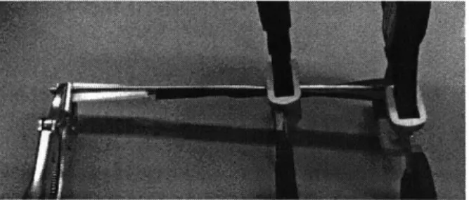
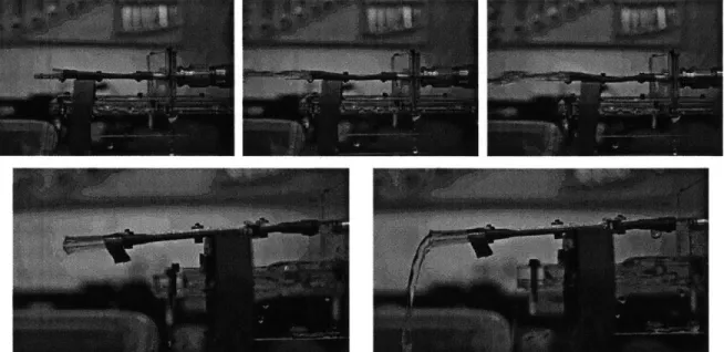
Figure 13: Flow regimes present during testing. The top row demonstrates the performance of the tube without an initiated collapse. Left to right: no flow, onset of separation, and fully developed flow separation. The bottom row demonstrates a collapse initiated at the upstream end of the tube by clamping a washer over the tube using an alligator clip. Since the alligator clip was clamped to the metal plate supporting the tube (see figure 14), the washer constrained but did not choke flow in the compliant section.
In order to gain some understanding of how the tube collapse would affect the pressure-flow rate relationship, a surrogate tube constructed using a sheet of silicone clamped into the "teardrop" shape with two aluminum plates was used (see figure 14).
This avoided the uneven glue seams (and thus additional duct roughness) in the joined tubes and excessive stiffness in the molded tubes. After once again observing flow separation, the tube was manually pinched toward the upstream end to initiate and earlier tube collapse and prevent flow separation. Data was then taken for tubes constructed of two varieties of silicone with and without the induced collapse and is presented below.
45.000 40.000 35.000 30.000 -25.000 20.000 15.000 10.000 U Shore A 10 constrained * Shore A 10 unconstrained A Shore A 35 constrained A Shore A 35 unconstrained 4 4
3
I
.4
40
a
4A
a
4a
4 4 4a
6
*4a
5.000 -0.000 0 0 2 4 6 Pressure (psi) 8 10 12Figure 15: Overview of data taken for tubes of two shore A hardnesses with and without an induced tube collapse. Red data points correspond to unconstrained tubes (no collapse initiated) whereas blue data points reflect tubes that were constrained at the upstream end to initiate collapse. Squares correspond to silicone tubes with a shore A hardness of 10 while triangles correspond to silicon tubes with a shore A hardness of 35. The collection of data for the shore A 10 tube with an induced collapse was curtailed as a result of a pressure buildup that appeared to threaten the tube's structural integrity.
30.000 -25.000 -- 20.000 -00 4 15.000-0 10.000 5.000 0.000 * Shore A 10 constrained A Shore A 35 constrained 12 -0.9734 R = 0.99797 0 2 4 6 8 10 12 Pressure (psi)
Figure 16: Isolating the occurrence of induced collapse, the pressure-flow rate response for two tubes of different hardness that have been pinched at the upstream end. Trendlines with R2
values provided for easier visualization.
45.000 -1 R2 = 0.97061 A Shore A 35 Clamped A Shore A 35 Unclamped R2 =0.9734 2 4 6 8 10 Pressure (psi) 40.000 35.000 -r 30.000 -25.000 -c 20.000 -- 15.000 -10.000 5.000 -0.000 0 12
From these data, several conclusions can be drawn. At least in the case of the shore A 35 test, the pinched and unpinched runs present different linear pressure-flow rate trends. This indicates that the induced tube collapse is at least providing a higher head loss by restricting the change in flow rate over a range of driving pressures. This is to be
expected with the reduction of cross-sectional area resulting from partial tube collapse. However, the relationships for both the pinched and unpinched shore A 10 emitters track each other very closely, indicating that this relationship might not be as clear-cut. Based on the data presented in figure 16, the conclusion could be drawn that altering the silicone hardness merely shifts the relationship, with a softer tube allowing less flow at an equal
driving pressure. However, this assertion is also somewhat questionable given that only four data points were collected for the pinched shore A 10 tube as a result of concerns
about material failure at higher pressures. Similar concerns cut off the other tests at 11 psi, with the shore A 10 tube being brought all the way to failure at 13 psi.
Going forward, a major issue with getting collapse to occur properly is the flow separation occurring at the downstream end of the system. One possible way to solve this is to force the separation to occur further upstream. In the clamped-sheet system used in testing and discussed previously as a production method, the collapse could be manually introduced at the upstream end by a mechanical perturbation of the tube. However, a
simpler solution could be to pull the diffuser effect further into the tube itself by shifting from an annular shape to a hollow conical shape. This would result in the flow expanding within the compliant section, thus reducing the likelihood of flow separation in the diffuser. Additionally, it provides a number of advantages for prior manufacturing methods. Casting tubes from LSR would become much more palatable with the addition of a draft angle,
although molds would end up having to be more complex to accommodate such a shape.
CONCLUSIONS
Despite the many challenges that still remain, silicone tubes remain a viable
alternative for low-cost pressure compensation emitters for drip irrigation systems. Going forward, there are several key areas to explore in future studies. On the metric of tube performance, the conical emitters have the potential to provide improvements over the current system by reducing flow separation and thus increasing the ability of the tube to autonomously collapse. On the criteria of cost and process simplicity, casting remains a method of interest for both lab scale mockups and eventual high-volume manufacturing. However, the silicone sheet folding and/or clamping process does demonstrate significant promise, and if the tolerances can be tightened it could present a viable and possibly
lower-cost alternative to casting. Of particular note here is the clamping method used briefly in testing, given that it abandons the unit manufacturing of the silicone ducts for using stock
silicone sheets in a mechanical assembly that can be manufactured much more flexibly. It remains to be seen whether or not that addition of more parts to the system can be offset by gains in efficiency by avoiding direct fabrication of the tubes by casting or joining.
REFERENCES
[1] Government of India, Ministry of Agriculture, 2004. Salient Findings and Recommendations
of Task Force on Microirrigation.
[2] Wiens, A. Josh, and Winter, Amos G., 2014. "A Novel Pressure-Compensating Valve for Low-Cost Drip Irrigation". ASME paper no. DETC2014-35131
[3] Tixier, Eliott, and Pawel Zimoch, 2013. "Bio-Inspired, Low-Cost, Self-Regulating Valves for Drip Irrigation in Developing Countries". ASME paper no. DETC2013-12495
[4] Shapiro, A. H., 1977. "Steady Flow in Collapsible Tubes". Journal ofBiomechanical
Engineering, 99, p. 126.
[5] Schwenker, Robert D., and Updegrove, Aaron, 2012. "To Mold, or Extrude, That is the
Question". Medical Design Technology, Web.
![Figure 1: Tube collapse in the regime of negative transmural pressure, taken from [2]](https://thumb-eu.123doks.com/thumbv2/123doknet/14679606.558923/7.918.174.711.449.768/figure-tube-collapse-regime-negative-transmural-pressure-taken.webp)