HAL Id: hal-00113826
https://hal.archives-ouvertes.fr/hal-00113826
Submitted on 14 Nov 2006
HAL is a multi-disciplinary open access
archive for the deposit and dissemination of
sci-entific research documents, whether they are
pub-lished or not. The documents may come from
teaching and research institutions in France or
abroad, or from public or private research centers.
L’archive ouverte pluridisciplinaire HAL, est
destinée au dépôt et à la diffusion de documents
scientifiques de niveau recherche, publiés ou non,
émanant des établissements d’enseignement et de
recherche français ou étrangers, des laboratoires
publics ou privés.
Restoration of voice timbre in telephone networks, based
on both voice and lines properties
Aline Neves, Gaël Mahé, Mamadou Mboup
To cite this version:
Aline Neves, Gaël Mahé, Mamadou Mboup. Restoration of voice timbre in telephone networks, based
on both voice and lines properties. Sep 2004, pp 1943-1946. �hal-00113826�
RESTORATION OF THE VOICE TIMBRE IN TELEPHONE NETWORKS BASED ON
BOTH VOICE AND LINE PROPERTIES
A. Neves, G. Mah´e and M. Mboup
Universit´e Ren´e Descartes- Paris V, 45 rue des Saints-P`eres 75270 Paris Cedex 06, France
phone: +33 1 44 55 37 53, fax: +33 1 44 55 35 35, email:{aline.neves,gael.mahe,mboup}@math-info.univ-paris5.fr web: www.math-info.univ-paris5.fr/crip5/spir.php
ABSTRACT
The voice timbre suffers from different forms of distorsions in a telephone link. In this paper, we propose a new blind equalizer for correcting these distortions, based on the com-bination of two different methods. The first one is a blind equalization method consisting in matching the long term spectrum of the processed signal to a reference spectrum, while the second one is a precompensation method, based on the physical characteristics of transmission lines. The new method is compared to the first one, showing a significant gain in performance.
1. INTRODUCTION
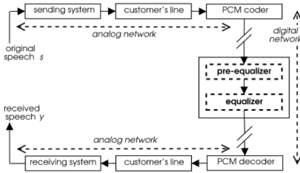
As we want to correct voice timbre distortions, we first define the timbre as the subjectively significant long term spectral characteristics of the voice of a given speaker. In the ana-log part of the PSTN (Public Switched Telephone Network) telephone link, as schematized in figure 1, the voice timbre suffers from two kinds of distortions.
The first one is the band-pass filtering (300-3400 Hz) at the end-points of the customer line (telephone terminal and line connections to the local exchange) in the transmission and reception paths. For the PSTN, this filtering is described on the average by the modified Intermediate Reference
Sys-tem (IRS) [1]. The frequency responses and masks of the
sending and receiving parts of the modified IRS, respectively called sending and receiving systems, are defined in [1].
The second distortion is due to the customer’s analog line, equivalent to a smooth low-pass filter. Its frequency response becomes steeper as the length of the line increases. A blind spectral equalizer, placed in the digital part of the network (see Figure 1), was proposed in [2] to compensate for these distortions and restore a timbre as close as possible to that of the original speaker voice. In this paper, we propose to enhance the performance of this equalizer by combining it with another method, proposed in [3]. This method was firstly developed to precompensate a transmission line based on its physical parameters, which are not taken into account in the first method. However, it needs the knowledge of the length of the line, which is generally not known.
We will review the blind spectral equalizer proposed by [2] in Section 2 and the precompensation method proposed by [3] in Section 3. Section 4 presents the new method, com-bining [2] and [3], which simulation results are shown in Sec-tion 5.
2. BLIND SPECTRAL EQUALIZATION
In [2], the authors treated the problem of correcting the voice timbre using an equalizer composed of two filters. The first
sending system customer’s line PCM coder
receiving system customer’s line PCM decoder pre-equalizer equalizer original speech s received speech y analog network analog network digital network
Figure 1: Telephone link with equalizer.
one is a fixed filter, called pequalizer, which frequency re-sponse is the inverse of the global rere-sponse of the average analog channel in the band[Fc− 3150 Hz]. The lower cutoff frequency Fcis fixed in order to avoid amplification of com-ponents with low signal to noise ratio (SNR). The average analog channel is defined as the combination of average cus-tomer analog lines with sending and receiving systems hav-ing frequency responses accordhav-ing to the nominal response of the modified IRS.
This filter is completed by an adapted equalizer, in order to adapt the global correction of the equalizer to various con-ditions of transmission. The frequency response of the sec-ond filter is computed as follows. Denoting G the frequency response of the analog channel,|S( f )|2the short-term power spectral density (PSD) of the original signal s and|Y ( f )|2the short-term PSD of the received signal y, we have:
|Y ( f )|2= |G( f )|2|S( f )|2 (1) If we assume the channel to be invariant, the time-averages of|Y ( f )|2and|S( f )|2are related by:
|Y ( f )|2= |G( f )|2|S( f )|2 (2)
The frequency response of the adapted equalizer is there-fore defined as:
|EQ( f )| = 1 |G( f )|= s γs( f ) γy( f ) (3)
whereγdenotes the long-term spectrum of a signal, defined as the time average of the short term spectrum.
Since the long term spectrum of the original voiceγs( f ) is unknown, it is approximated in [2] by the average spec-trum of speech defined in [4], called reference specspec-trum and denoted byγref( f ). Moreover, since the equalizer is placed
Figure 2: Precompensation system model
in the digital part of the network,γy( f ) is not directly avail-able and therefore it must be derived from the input of the equalizer, u, using:
γy( f ) = |L RX( f )|2|S RX( f )|2γu( f ) (4) where L RX is the frequency response of the receiving line and S RX is the frequency response of the receiving system. The frequency response of the adapted equalizer is then:
|EQ( f )| = 1 |L RX( f )||S RX( f )| s γref( f ) γu( f ) (5)
Only the band Fc− 3150 Hz is equalized; the values of
|EQ| out of this band are therefore replaced by a linear
ex-trapolation of |EQ|[Fc−3150 Hz], before deriving the impulse response of the equalizer from|EQ| by an IFFT.
Because of the roughness of the approximationγs( f ) =
γref( f ), only the global shape of this frequency response is
relevant. That is why the frequency response |EQ| must be smoothed. This smoothing is achieved by a narrow Hamming-windowing of the impulse response [2]. In the se-quel, the equalizer shown here will be referenced as BSE-W,
i.e. blind spectral equalizer smoothed by a windowing of
the impulse response. This smoothing is however not ideal, since it leads to irrelevant oscillations in the global frequency response of the equalizer link.
3. PRECOMPENSATION BASED ON THE CUSTOMER’S LINE MODEL
The customer’s line, shown in Figure 1, can be modelled as a transmission line using the following system of equations:
L∂i ∂t = −Ri − ∂v ∂x C∂v ∂t = − ∂i ∂x− Gv (6)
where v(x,t) and i(x,t) are, respectively, the tension and the
current at a distance x from the origin, at a time t. The line parameters are R, the resistance, L, the inductance, C, the capacity and G the conductance per unit length. The transmitted signal, i.e., the signal at the beginning of the line is s(t) = v(0,t) and the signal at the end of the line is y(t) = v(ℓ,t) where ℓ is the length of the line.
In [3], the authors treated the problem of precompensat-ing the signal transmitted through a transmission line chan-nel modelled as in (6). The goal is to anticipate the chanchan-nel distortions in order to obtain a channel output signal, y(t),
as close as possible to the original signal s(t), as shown in
Figure 2. In [3], the transfer function of the precompensa-tion filter, H( f ), is found by inverting the channel, i.e., by
finding the transmission line input as a function of its out-put. Considering (6) with boundary conditions v(0,t) = s(t)
and y(t) = v(ℓ,t) = Zi(ℓ,t), and with zero initial conditions,
v(x, 0) =∂v
∂t(x, 0) = 0, [3] finds the following transfer func-tion for the inverse channel:
H( f ) = cosh (ℓβ) +R+ iωL Z
sinh(ℓβ)
β (7)
whereβ(ω) =√−LCω2+ iωRC andω= 2πf .
H( f ) can be used in our context, presented in Section 1,
as a post-processor instead of a pre-processor, equalizing the transmitter customer’s line. However, it needs the length of the line, a parameter that is generally not known.
4. PROPOSED METHOD
We consider here the telephone link shown in Figure 1. The frequency responses of the receiving system and the recep-tion line (S RX and L RX respectively) are assumed to be known, as in section 2, and, in addition, so are the sending system and the parameters R, L, C and G of the line. The pre-equalizer compensates the distorsions caused by the sending and receiving systems and the reception line.
Under these assumptions, the frequency response of the adapted equalizer is the inverse of the transmission line re-sponse and is given by the precompensation method (7). The only problem is that (7) needs the length of the line, a param-eter that is not known. A solution is to look for the length ℓ for which H( f ) is the best possible approximation of the
fre-quency response of the adaptive equalizer, EQ, computed as in Section 2, in the frequency range of interest Fc− 3150Hz. For this purpose we compare H and EQ in the cepstral do-main, the cepstrum of a filter of frequency response H being defined by:
CH= IDFT (ln(|H|)) (8) We define the cost function to be minimized as the distance between H and EQ in the space of the ten first cepstral coef-ficients: J= 10
∑
k=1 ³ CEQk −CkH´2 (9)where CkEQis the kth cepstral coefficient related to EQ and
CkHis the kth cepstral coefficient related to H. The interest in using this space of comparison instead of the spectral domain lies in:
- the fact that it allows the comparison between the shapes of the frequency responses without considering their level, simply by excluding the cepstral coefficient of order zero;
- the possibility of controlling the spectral resolution of the comparison, since it depends on the number of cep-stral coefficients involved in the comparison.
A gradient descent algorithm was implemented using the following recursion equation:
ℓn+1= ℓn−µ∇ℓJ(n) (10) whereµis the step constant and
∇ℓJ(n) = − 11
∑
k=1 ³ CkEQ−CHk(ℓn) ´∂CH k ∂ℓ (ℓn) (11)The differentiation of CHwith respect to ℓ gives:
∂CH ∂ℓ = IDFT Ã 1 p|H| µ H∗∂H ∂ℓ + H ∂H∗ ∂ℓ ¶! (12)
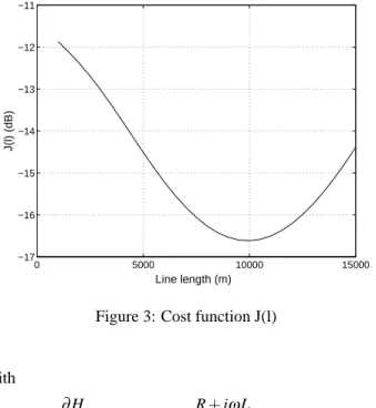
0 5000 10000 15000 −17 −16 −15 −14 −13 −12 −11 Line length (m) J(l) (dB)
Figure 3: Cost function J(l)
with
∂H
∂ℓ =βsinh(βℓ) +
R+ iωL
Z cosh(βℓ) (13)
Figure 3 shows a typical exemple of the cost function J as a function of ℓ. As we can see, the curve has only one minimum, even though the presence of local minima can not be completely discarded due to the random nature of EQ. For this simulation, the customer’s line had a 10 km length.
We call this new method blind spectral equalization based on physical parameters (BSE-P).
5. SIMULATION AND RESULTS
We have compared the performances of the BSE-W method proposed in [2] with the BSE-P method discussed in Sec-tion 4. The analog part of the simulated telephone link is composed of a long transmission line, an average reception line and sending and receiving systems having frequency responses according to the nominal response of the modi-fied IRS [1]. A typical telephone line has: R=168 mΩ, L= 0.7mH, C=50pF and G=0 [5]. The impedance at the end of this line, denoted Z, is the input impedance of the hybrid de-vice (2 wires/4 wires connection). Typical values are a 600Ω resistive impedance or a 270Ωresistance in series with a cell of 750Ωin parallel with a 150nF capacitor (new devices) [5]. Simulations were done using a set of 34 different speak-ers uttering a text of approximately 20s of voice activity. The signal was divided in slots of 256 samples, with 50% of over-lapping. Fcwas set to 200 Hz. The average line length was considered equal to 2km while the customer’s line is 10 km long. Its parameters values R, L, C and G are given above and Z was considered complex.
For the BSE-W, the adaptive equalizer filter had 15 co-efficients and was computed as in Section 2. For the BSE-P, the algorithm given by (10) was initialized with ℓ(0) = 2km,
given that this is the average length value of a customer line, and the step constant,µ, was set equal to 5.103.
We have used two forms of comparison. In the first one, we measured the performances by means of the cepstral
er-ror, CE. For each m-th signal slot, CE is defined as [6]:
CEm= v u u t 20
∑
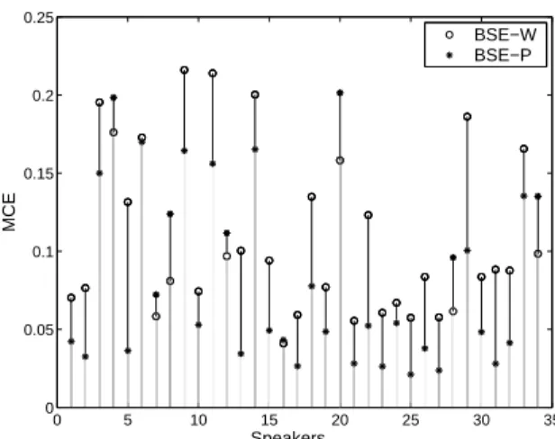
k=1 ¡Ci k(m) −Cke(m) ¢2 (14)where Cikis the kth cepstral coefficient of the ideal equalizer (inversion of the line without errors) and Ckeis the kth cepstral coefficient of the equalizer being tested. Figure 4 shows the comparison between the mean cepstral errors (MCE), com-puted as a time average of the cepstral errors, for the 34 speakers tested. We can observe that, for the large major-ity of the cases tested, the BSE-P achieves a smaller MCE. However, there are cases where the BSE-W has a better per-formance. Note that the BSE-W tries to recover the voice timbre using a ruder approach, that is afterwards refined by the BSE-P method. Thus, if this first approach, given by EQ, is satisfactory, the BSE-P will enhance the performance of the system, giving a better result. However, if it is not satis-factory, the BSE-P will try to refine something that is already bad, leading to a worse result.
The algorithm used, given by (10), considered 10 cep-stral coefficients. Simulations have shown that increasing this value does not result in a better performance.
For an easier visualization of the difference between the two methods, we also compared the systems global fre-quency responses. Figure 5 shows an example of the result obtained (speaker number 13). We can clearly see that the P response is closest to the ideal response than the BSE-W method.
Finally, Figure 6 shows the equalizers frequency re-sponses, comparing |EQ|, given by (5), the smoothing ob-tained using the Hamming window and the result obob-tained using BSE-P. We can see that this last one almost superposes the ideal equalizer response.
Since our goal is to restore the voice timbre, the interest of this cepstral error reduction lies in its subjective impact. Relationships between cepstral error and timbre restoration were established in [6] based on formal subjective tests. Since these relationships were established in the same con-text and for similar cepstral and spectral distorsions, we can use them to evaluate the perceptual meaning of these results. According to [6], the BSE-P leads to a significant improve-ment of the timbre restoration for at least speakers 5 and 29 (Figure 4).
6. DISCUSSION
One could object to this method that it needs the knowledge of too many parts of the link: sending and receiving systems and the receiver line. This strong assumption was made only to stay in the frame of [2], in order to evaluate the gain of our new method. In practice, few elements of the link have to be known.
Let us consider the link schematized in Figure 7, where the voice timbre of speaker B is to be restored for speaker A in reception. The transmission path from B to the 2 wires / 4 wires connection can be estimated using the BSE-W method. Then, knowing the frequency response of the sending system of A, we can estimate the length of the analog line of A using the BSE-P method. At last, knowing the frequency response of the receiving system of A, we deduce the frequency re-sponse of the complete analog channel from B to A. Thus,
0 5 10 15 20 25 30 35 0 0.05 0.1 0.15 0.2 0.25 Speakers MCE BSE−W BSE−P
Figure 4: Comparison between the cepstrum errors of the two methods 103 −5 −4 −3 −2 −1 0 1 2 3 4 Frequencies (Hz) Amplitude (dB) BSE−P BSE−W ideal equalizer
Figure 5: Comparison between the frequency response of the global systems
we only need to know the characteristics of A’s terminal to offer A a restored timbre of B.
7. CONCLUSION
In this paper we developed a new blind equalization algo-rithm for correcting the voice timbre distortions in a tele-phone link. To do so, we based ourselves on the precompen-sation method proposed by [3]. Since this method needs the knowledge of the line length, we developed a blind way to find this information using the blind spectral equalizer pro-posed in [2] and a cost function which minimization leads to a good estimation of the line length.
The comparison of this new method with the one pro-posed in [2] showed a significant gain in performance and substantial improvement in the voice timbre restoration for the large majority of the cases tested.
8. ACKNOWLEDGEMENTS
We thank gratefully Vincent Barriac and Joseph Bellœil (France Telecom R&D) for their helpful information on net-works and devices.
102 103 −8 −6 −4 −2 0 2 4 6 8 10 12 Frequencies (Hz) Amplitude (dB) |EQ| ideal equalizer |H(f)| Hamming window
Figure 6: EQ(f) before smoothing, H(f) with ℓ obtained by (10) and EQ(f) smoothed by the Hamming windowing
EQ D/A
A/D
A/D
D/A
analog line analog line
digital link
A B
Figure 7: Link between two users
REFERENCES
[1] ITU-T Recommendation P.830, Subjective performance
assessment of telephone-band and wideband digital codecs, annex D, 1996.
[2] G. Mah´e and A. Gilloire, “Correction of the voice timbre distorsions on telephone network,” in Proc. Eurospeech, pp. 1867–1870, 2001.
[3] M. Fliess, P. Martin, N. Petit, and P. Rouchon, “Com-mande de l’equation des t´el´egraphistes et restauration active d’un signal,” Traitement du Signal, vol. 15, no. 6, pp. 619–625, 1998.
[4] ITU-T Recommendation P.50, Artificial voices, 1993. [5] ITU-T Recommendation Q.552, Commutation and
Sig-naling, 2001.
[6] G. Mah´e, Correction Centralis´ee des Distorsions
Spec-trales de la Parole sur les R´eseaux T´el´ephoniques, Ph.D.