Internationale Zeitschrift für Bauinslandsetzen 2. Jahrgang, Heft 1,1996
The Role of Moisture in the Carbonation of
Cementitioiis Materials
Y. F. Houst
Laboratory for Powder Technology
Federal Institute of Technology, EPF Lausanne, Switzerland
Abstract
It is well known that water, either in the solid, liquid or gaseous state, plays a prominent role in the behaviour of porous materials like cementitious composites. Carbonation is not an exception. The modification of the macrostructure of different hydrated cement pastes (hep) due to carbonation is presented and discussed from the point of view of the water content which is a function of the relative humidity. The transport properties of the carbonated hep for CO2 and O2 diffusion were measured with different water content. Finally, the carbonation shrinkage was also measured as a function of the relative humidity. It was found that carbonated materials were much less sensitive to the relative humidity of the surrounding atmosphere than non-carbonated ones. All these results lead to the proposition of a model of a porous system with two levels of porosity.
Key words: carbonation, hardened cement paste, gas diffusion, carbonation shrinkage, porous structures
Einfluß des Feuchtigkeitsgehaltes auf das Karbonatisieren zementgebundener Werkstoffe
Zusammenfassung
Es ist hinreichend bekannt, daß Wasser in jedem Aggregatzustand, fest, flüssig oder ga49nfluß auf die Eigenschaften poröser Körper wie etwa zementgebundene zusammengesetzte Werkstoffe hat. Karbonatisieren macht da keine Ausnahme. Die durch das Karbonatisieren an unterschiedlichen Zement steinproben hervorgerufenen Veränderungen des Makrogefiiges werden beschrieben und unter dem Aspekt des
von der relativen Feuchte abhängigen Feuchtigkeitsgehaltes diskutiert. Die Transportparameter des Zementsteins für die CO2 - und die O2- Diffusion werden bei unterschiedlichem Feuchtigkeitsgehalt bestimmt. Das Karbonatisierungschwinden wurde auch als Funktion der relativen Luftfeuchtigkeit gemessen. Es stellte sich dabei heraus, daß karbonatisierte Proben viel weniger empfindlich auf Änderungen der relativen Luftfeuchtigkeit der Umgebung reagieren als nichtkarbonatisierte. Alle Ergebnisse zusammen genommen erlauben uns ein Modell für das poröse Gefüge des Zementsteins mit bimodaler Verteilung der Porengrösse vorzuschlagen.
Stichwörter: Karbonatisieren, Zementstein, Gasdiffusion, Karbonatisierungsschwin-den, poröses Gefüge
Dr. Yves F. Houst received his Degree in chemistry from Lausanne University and his Doctorate in materials science from the Federal Institute of Technology in Lausanne (EPFL), Switzerland. He is actually the Head of the Cement Group of the Laboratory for Powder Technology of the EPFL. He is involved in various research programmes related to properties of cement suspensions, admixtures and durability of cementitious materials.
1. Introduction
Carbonation of concrete is often at the origin of the corrosion of the steel reinforcement which is still actually one of the main causes of the degradation of concrete structures [1]. This fact is not due to a lack of interest. In 1987, Parrott [2] compiled a bibliography on carbonation and reviewed 182 papers, essentially from the last 20 years. The carbonation phenomenon has been known for a long time. For instance Zschokke [3], in a paper dating from 1916, describes already precisely the carbonation of concrete and its causes, the corrosion of the reinforcement in carbonated concrete and the preventive measures which can be taken to limit the degradation.
Despite these efforts, the problem remains with us. As the cost of repair of concrete structures has dramatically increased the last 20 years, even the general public is aware of the problem. It is important to point out that, if the means at our disposal to limit the carbonation are well known, the penetration of chloride ions (coming generally from deicing agents) is much more difficult to combat.
It is possible nowadays to use numerical simulation methods to study quantitatively complex interactive processes like carbonation. Such an attempt has been undertaken and a numerical model proposed to forecast the service life of reinforced concrete structures [4], But, the lack of quantitative data hinders the development of such models and limit their predictive powers. For this reason, a study on five subjects which influence durability of reinforced concrete has been carried out, namely the modification of the microstructure caused by carbonation [5], the measure of the diffusivity of CO2 and O2 through carbonated hydrated cement paste (hep) [6] and mortar [7], the carbonation shrinkage [8] and the ingress of carbon dioxide into mortars exposed outdoors [9].
More recently, the effect of carbonation on cementitious waste forms for nuclear and non nuclear applications have become a new subject of interest. It was shown that leaching is lowered by carbonation [10]. The effect of carbonation on the immobilisation of Cr(III) and Cr(VI) has been studied in both Portland and blended cements containing blast furnace slag [11]. The results show that, although Portland cement matrices are more resistant to carbonation than those containing slag cement, the increase of chromium content in pore solution is more marked for Portland matrices.
The aim of this paper, based on results given in [5-8], is not to describe the general problem of the carbonation, which has already been largely treated (see for instance [12]), but essentially to indicate more precisely the role of water content on gas diffusion through cementitious materials.
Measurements of the carbonation depth profiling on mortars exposed outdoors [9] have shown that the depth of carbonation cannot be represented by a sharp reaction
front separating non carbonated and carbonated zones. In reality, a transition zone whose width depends on the material properties, is observed. A typical calcium carbonate depth profile is represented in Fig. 1. These observations have lead us to propose a model with two kinds of pores. This model, which is presented later, allows us to describe the diffusion of CO 2 through the cementitious material and the width of the transition zone.
Fig. 1 : Schematic calcium carbo-nate (CaCC>3) depth profile due to carbonation after a certain time
CaC03 transition \ zone fully 1 non carbonated 1 carbonated partially \ carbonated
Abb. 1 : Schematische Darstel-lung des Tiefenprofils von Kalziumkarbonat nach einer be-stimmten Karonatisierungsdauer
depth
2. Physico-chemical basis 2.1 Carbonation
Carbonation of hydrated cement compounds, i.e. essentially calcium hydroxide (Ca(OH)2) and calcium silicate hydrate (C-S-H1), is a chemical reaction of neutralisation of bases by an acid, the carbon dioxide in the air, which can be represented by the simple equations (1) and (2):
Ca(OH)2) + CO2 — > C a C 03 + H20 C-S-H + CO2 — > CaCC>3 + S1O2 + H2O
(1) (2) In fact, these reactions take place in solution and the reactants have to dissolve before reacting. The solubility of calcium hydroxide is reduced by sodium and potassium hydroxides. These reactions induce a reduction of the pH of the pore solution to such a value that the steel reinforcement is no longer protected against corrosion.
The rate of carbonation, i.e. essentially the ingress of CO2 into a porous material, can be treated as a diffusion process. At the steady state, the one dimensional diffusion of a gas through a porous system can be described by Fick's first law:
J is the flux of the gas, De the effective diffusion coefficient or diffusivity, Ac the CO2 concentration in the atmosphere in contact with the material and d the depth of carbonation. In fact, the carbonation front at a given time can be represented by a certain volume where the cement paste vary from fully carbonated to non-carbonated. In this equation, it is assumed that the reaction of CO2 is instantaneous. This assumption can certainly be admitted, because the reaction of CO2 is much more rapid than its diffusion.
The microscopic mechanisms of diffusion are complex and have been discussed in numerous publications [6, 13, 14]. We wish only to underline that the diffusivity is independent of the pore dimensions for "large" pores (diameter >450 nra for CO2 at 20°C and 1 atm) only. For small pores (diameter < 45 nm) the diffusivity is proportional to the pore diameter.
The diffusivity De is influenced by the porosity, the cement content, the degree of hydration, the water to cement ratio, etc. The free volume for gaseous diffusion depends on the water content of the porous material which depends itself on the relative humidity (RH) of the surrounding air and on the pore-size distribution. 2.2 Pores and water
Chemically bound water excepted, water in a cementitious material can be divided into adsorbed, condensed capillary water and, in large capillaries and air pores, free water. All pores can be filled by water when the porous material is immersed into water for a sufficient time. In capillaries, condensation takes place at a lower relative humidity than 100%, depending on the pore radii. This is due to the lower vapour pressure above a concave liquid meniscus than above a plane liquid surface. Kelvin's equation relates the maximum radius rk of pores filled by water and the relative humidity (p/po) : (3) i"k = 2 y v m (4) RT ln(p/po )
where γ is the surface tension of water, Vm the molar volume of water, R the gas constant and Τ the absolute temperature. Kelvin's equation is only valid for capillary condensation, i.e. only for relative humidities where the desorption isotherm curve
exhibits a hysteresis. In fact, the real radius rp is higher than the Kelvin's radius rk. For cylindrical pores in hygro-thermal equilibrium, one has :
where t is the statistical thickness of the adsorbed water layer measured on the plane surface of the same material, but non-porous. Before capillary condensation can take place (at low RH), pore walls are covered by a film of water molecules of thickness t which also reduce the empty porous volume. For instance, this thickness is about 0.4 nra at 40% RH and 0.8 nm at 90% RH.
A schematic representation of a porous network with capillary condensation is given in figure 2. In such a case, the CO2 molecules cannot penetrate the porous system in the gaseous state. They have to dissolve and to diffuse through water. The diffusion in a liquid is about 10Ό00 times slower than in air. It is obvious that through such a very fine network of capillaries, diffusion of CO2 will be very much influenced by the relative humidity.
One can see from equations (1) and (2) that carbonation of Ca(OH)2 and C-S-H forms CaCC>3. Carbonation of Ca(OH)2 into CaCC>3 causes an increase of volume, depending on the crystal form, which is 3% for aragonite, 12% for calcite and 19% for vaterite. Calcite is the stable form under normal temperature and pressure and is the main kind of calcium carbonate formed by carbonation. The chemical reactions lead to a reorganisation of the microstructure, a decrease of the porosity, and, paradoxically, a decrease in total volume involving a differential shrinkage between the surface and the bulk of the material which can lead in certain cases to cracking. An acceleration of the carbonation rate can result from this cracking.
The interfacial transition zone around the aggregates is more porous and reacts more rapidly than the bulk. Because of the carbonation shrinkage, it can result in microcracks which are known to develop preferentially at interfaces.
rp = rk + 1 (5)
Fig. 2: Schematic representa-tion of a porous network par-tially filled by condensed water.
Abb. 2: Schematische Darstel-lung eines porösen Gefiiges, das teilweise durch Kapillarkonden-sation mit Wasser gefüllt ist.
3. Experimental
3.1 Hydrated cement pastes (hep)
Portland cement paste cylinders of 138 mm diameter were prepared. After six months of curing in lime water, discs of 1-3 mm thickness were cut off. In order to avoid sedimentation and bleeding at high water /cement ratio (W/C), it was necessary to assure that cement particles were kept in suspension before setting. Cement and water were mixed and placed under vacuum and the cylindrical mould was then placed on a roller device for rotating the mix during setting and hardening, usually for a period of 48 to 72 hours. This method allowed us to prepare hep with a W/C ratio from 0.3 to 0.8. Then, some specimens were artificially carbonated at 76% relative humidity (RH) in an atmosphere of 80% to 90% CO2 until complete carbonation, checked by the Phenolphthalein test and X-ray diffraction was performed.
3.2 Water adsorption isotherms
The samples crushed to pieces of 3 to 5 mm and dried at 105°C were first placed in desiccators in which different relative humidities were maintained by saturated salt solutions. After the equilibrium was reached, the water uptake was measured by weighing. The water content as a function of the relative humidity allowed us to construct the adsorption isotherms. All adsorption experiments were carried out at 18°C on non-carbonated and carbonated hep.
3.3 Mercury Intrusion Porosimetry (MIP)
A porosimeter which allows the application of pressures up to 415 MPa has been used. This corresponds to a minimum radius of 1.7 nm. After having introduced a number of simplifying assumptions, the radius r of cylindrical pores, which can be penetrated by mercury at pressure P, can be related by the following equation:
2 σ cos θ
r = - ρ (6) where σ stands for the surface tension of mercury and θ for the contact angle
hep-mercury. A value of 135° for θ was used in this study. The pore-size measurements have been carried out on small pieces of hep (3 to 5 mm) pre-dried at 70°C.
3.4 Diffusion measurements
We have developed a special measuring cell which allows us to simultaneously determine the diffusion coefficients of O2 and CO2 as a function of the relative humidity by a non-steady state method [6], The measuring cell (Fig. 3) is divided
into two chambers by the porous disc of hep. Once the specimen is built into the measuring cell, nitrogen with a given moisture content is introduced into both chambers of the cell. The flow of pure nitrogen is continued until no more oxygen and carbon dioxide can be measured in the lower chamber. At this time, the two chambers contain only nitrogen with the same moisture content. Then, the premixed gas (2% CO2, 20% O2 and 78% N2) enters only the upper chamber of the cell. After a few minutes the gas composition in this chamber is the same as that of the premixed gas, which is moistened by bubbling a given part of the gas through water. Oxygen and carbon dioxide diffuse now from the upper chamber through the hep or mortar disc into the lower chamber, where the two gases are monitored as a function of time by gas analysers based on the paramagnetic properties of oxygen and infrared absorption of carbon dioxide.
78% N2 membrane manometer • RHy , ' Λ 1 analysers N2 lower chamber OO2 O2
Zi
Fig. 3: Schematic representa-tion of the experimental set-up for gas diffusion measurements.
Abb. 3: Schematische Darstel-lung des Versuchsaufbaus zur Bestimmung der Gasdiffusion.
All measurements were carried out between 20 and 25 °C. Relative humidity was continuously checked in the two chambers by humidity sensors. The effective diffusivities are deduced from the curves of gas concentration as a function of time. The duration of the measurements varied between 1 and 3 days, depending on the thickness and porosity of the samples.
3.5 Carbonation shrinkage
For the carbonation shrinkage measurements, three prisms of hep 3/3/90 mm were glued to form a specimen stiff enough to allow us to measure their length changes. The advantages of such little prisms are essentially the relatively short time to reach hygral equilibrium and then a large carbonation shrinkage. The specimens were fixed
in a special holder and placed into an incubator with controlled relative humidity at 30 °C. The drying shrinkage was measured with inductive gauges and the length changes were recorded as a function of time. After drying at a constant RH until equilibrium lengths were measured, CO2 was introduced and its concentration kept constant at 2% by volume. The carbonation shrinkage was then recorded during about 80 to 120 days, depending on the rate of shrinkage.
4. Results and discussion 4.1 Microstructure
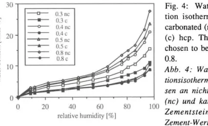
The water adsorption isotherms of the three different samples of hep, measured on non-carbonated and carbonated samples, are shown in Fig. 4. The results of the hep with W/C = 0.3 and carbonated are not given, because even after more than five years of exposure to the atmosphere of CO2, discs are carbonated only to a depth of 0.2 to 0.3 mm. Carbonation causes a decrease in the amount of adsorbed water as has been already observed [15]. The higher the equilibrium moisture content in a non-carbonated hep, the higher the decrease of moisture content in an identical but carbonated hep. The adsorption isotherms of carbonated hep of W/C between 0.4 to 0.8 do not vary to a large extent. For example, the equilibrium moisture content of these hep at 97% RH runs from about 8.5% to 11%. The BET specific surface area was calculated from the data of the adsorption isotherms between 9 and 44% RH and the results are reported in Table 1. Carbonation strongly reduces the specific surface area to an approximately constant value of 57 to 62 m2/g for the three higher W/C.
Fig. 4: Water vapour adsorp-tion isotherms (18°C) of non carbonated (nc) and carbonated (c) hep. The W/C ratio was chosen to be 0.3, 0.4, 0.5, and 0.8.
Abb. 4: Wasser dampf adsorp-tionsisothermen (18°C), gemes-sen an nicht karbonatisiertem (nc) und karbonatisiertem (c) Zementstein. Der Wasser/ Zement-Wert betrug 0.3, 0.4, 0.5 und 0.8.
The influence of carbonation on the microstructure was quantitatively measured in addition by mercury intrusion porosimetry. The results are shown in Fig. 5. The
porosity is significantly reduced by carbonation (table 1). This reduction is greater for low W/C. All the pores of the hep of W/C = 0.4 are affected by carbonation, but in particular those with radii below 0.1 μπι. The very porous hep with W/C = 0.8 reveals a reduction of the amount of pores with radii below 2 μπι. These results roughly confirm those previously published [15,16J. However, the pretreatement of hep (duration of hydration, type of drying, carbonation, etc.) has a major influence on the microstructure and it is difficult to compare precisely the results from specimens with different histories. It should be noted that mercury porosimetry does not measure pores with radii > 300 μπι. The smallest pores (gel pores) are only partly measured by this technique. Thus, the true porosity is certainly higher and closer to that determined after water saturation (Table 1). The increase of the bulk density shows the densification due to carbonation.
By using equation (5), it is possible to calculate the pore-size distribution of the pore cores at a given RH. An example is given in Fig. 6 for the carbonated hep of W/C=0.4. The pore cores porosity was calculated for 4 different RH. One can see that the porosity of the dried specimen (13.4%) is strongly reduced at 95% RH (5.4%). This behaviour is similar for the other specimens, since they have approximately the same volume of pores <0.023 μπι in radius, those in which capillary condensation takes place at 95% RH. The relative decrease is obviously lower since the total porosity is higher.
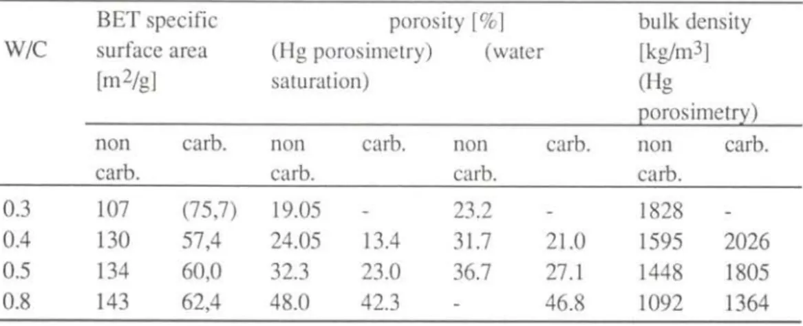
Table 1 : Porosity, bulk density and BET specific surface area of hep.
Tabelle 1 : Porosität, Rohdichte und BET-Oberfläche des Zementsteins.
BET specific porosity [%] bulk density W/C surface area (Hg porosimetry) (water [kg/m3]
[m2/g] saturation) (Hg
porosimetry) non carb. non carb. non carb. non carb.
carb. carb. carb. carb.
0.3 107 (75,7) 19.05 - 23.2 - 1828
0.4 130 57,4 24.05 13.4 31.7 21.0 1595 2026 0.5 134 60,0 32.3 23.0 36.7 27.1 1448 1805
c o o δ, Ό υ "3 Ε D υ .001 .1 1 10 radius [μιη] Hilf ι ι ι i f f — » ι l i π · ; -.1 1 10 radius [μιη] 1000
Fig. 5: Porosity of non-carbonated (a) and carbonated (b) hep measured by mercury intrusion porosimetry.
Abb. 5: Porengrössenverteilung des nichtkarbonatisierten und des karbonatisierten Zementsteins, bestimmt mit der Quecksilberdruckporosimetrie.
o o, TD D 0.15 0.10 a 0.05 ε υ 0.00 ι n u r · ; ι ι .001 .01 ιlll| i ι ΙΙΙ»Ι| 1 10 radius [μιη] Fig. 6: Porosity of " e m p t y " pores (not filled by water) of the hep of W/C=0.4 (carbonated) for different relative humidities at 18 °C. The curve at 0% RH is the direct result of the MIP measurement.
Abb. 6: Porengrössenverteilung der leeren, nicht mit Wasser
1000 gefüllten Poren des
karbonatisierten Zementsteins mit VV7Z -0.4 bei 18°C und unterschied-lichen relativen Feuchtigkeiten. Die mit 0% bezeichnete Kurve wurde mit der Quecksilber-druckporosimetrie bestimmt.
4.2 CO2 and O2 diffusion
Measurements have been carried out on different samples of a thickness between 1 to 3 mm. It was found that the effective diffusivity of CO2 does not depend on the CO2 concentration between 0.8% to 1.8% and that of O2 between 10% to 19.5%. The diffusivity calculations have been made with the results measured in these ranges.
The effective diffusivities of the two gases as a function of the relative humidity are represented graphically in Fig. 7a. The curves of this figure were calculated by fitting the following function to experimental data:
De = k(l-P/Ps)n (7)
P/Ps stands for the equilibrium relative humidity and k and η are characteristic parameters of the material which are given in [6]. This empirical function describes in a satisfactory way the influence of the RH on the effective diffusivity of CO2 and O2. The influence of humidity is much lower than that determined on non-carbonated materials. This is due to the large reduction of the equilibrium water content caused by carbonation. The results show that the influence of RH on the diffusivity is noticeable only for hep with a low macroporosity, i.e. that of W/C < 0.5. The porosity of these hep consists essentially of micro- and meso-pores where water can adsorb and condense. Thus, the porous volume allowing gas diffusion is reduced.
The influence of the water content as taken from the water adsorption isotherms is shown in Fig. 7b. This representation has to be modified in the case of a desorption equilibrium, as there is an appreciable hysteresis between adsorption and desorption isotherms.
relative humidity[%]
2 4 6 8 10
water content [%]
Fig. 7: Effective diffusivity of carbonated hep versus: (a) relative humidity and (b) water content ; W/C is given as a parameter.
Abb. 7: Effektiver Diffusionskoeffizient des karbonatisierten Zementsteins auf getra-gen als Funktion (a) der relativen Luftfeuchtigkeit und (b) des entsprech-enden Feuchtigkeitsgehaltes.
The diffusivity of CO2 is always lower than that of O2· This is mainly due to the difference in size of the two molecules
The very similar behavior of O2 and CO2 suggests that surface diffusion must be negligible f o r the two gases. The molecules have different polarities and consenquently should have different affinities for pore surface. Measurements carried out on mortars lead to similar general conclusions [7].
The influence of RH or of the water content, has already been studied, but on non-carbonated mortar and concrete [17,18]. These materials were in fact not in hygral equilibrium and their water content was not well known. The water vapor diffusivity through non-carbonated and fully carbonated hep has been measured as a function of the equilibrium water content [19]. It was also found that the influence of the RH was much lower on carbonated than on non-carbonated hep. The diffusivities of O2 we have determined, are in general agreement with those of the literature cited above. 4.3 Carbonation shrinkage
The following hyperbolic function, often used to describe shrinkage phenomeno-logically, has been fitted to experimental points:
A! = _aL (8)
I b+t
were Δ1/1 is the carbonation shrinkage, t the time and a and b are parameters. The parameter "a" is equal to the final shrinkage (t=°°) and " b " the time necessary to reach half of the final shrinkage.
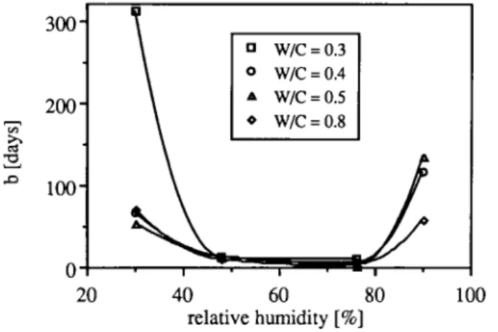
This time is at minimum between 50 and 80% RH (Fig. 8). It is also in this range that the rate of carbonation is at maximum [20], The rate of carbonation shrinkage is therefore dependent on the rate of carbonation. At high RH, the rate of carbonation is controlled by CO2 diffusion or by water diffusion out of the reaction zone. The role of water depends on the CO2 concentration and on the porosity of hep. It has been shown that an increase in the CO2 concentration does not always induce an acceleration of the carbonation rate, because the release of water blocks capillary pores, thus decreasing CO2 diffusion [21], In our case, this effect is certainly important. Indeed, the influence of the RH on parameter b is much higher than that observed on the diffusivity of CO2. At low RH, the pore water content allowing dissolution of Ca(OH)2 is the limiting factor of carbonation rate. More detailed results are given in [8].
Λ 1 0 0 -c/5 Λ Ό 300" 2 0 0 -0
Abb. 8: Notwendige Zeit, um die Hälfte des Endwertes des Schwindens zu erreichen (Para-meter b aus Gleichung 8).
Fig. 8: Time necessary to ob-tain half of the final shrinkage (parameter b of equation 8).
20 40 60 80 100
relative humidity [%]
5. Bulk and local diffusion
The diffusivity measurements were carried out in order to describe the transport of CO2 through a carbonated material, i.e. a non-reactive material. We have also assumed that CO2 in the gaseous state and dissolved in pore and adsorbed water were in equilibrium. The measured diffusivity can serve for numerical calculations describing the C O 2 diffusion through the carbonated layer before arriving at the carbonation front.
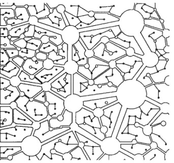
We have observed that, after a given time, the amount of carbonate produced during carbonation is relatively low, more especially for low W/C [8]. The same observation has been made on mortars [9]. On mortars of low W/C, though the carbonation rate is low, the depth of carbonation is comparatively high. This statement leads us to propose a model of two microstructural levels that apply especially to hep and mortar with low or moderate porosity. The border between these two levels is 0.1 to 0.5 μπι. The first level comprises the micro-, meso- and a part of the macropores. It is essentially in this domain where capillary condensation and adsorption play a major role. Gas diffusion is slow and strongly influenced by the water content. Pores are long and tortuous. At the second level, which comprises the largest macropores and air pores, the gas diffusion is faster. Such a porous system is schematically represented in Fig. 9.
Fig. 9: Schematic represen-tation of the bi-porous system of hep.
Abb. 9: Schematische Darstel-lung des biporösen Gefüges in Zementstein.
The porosity is strongly magnified, but it is easy to distinguish the network of coarse interconnected pores allowing a quite direct ingress into the material. Between the large pores of this network, another network of fine pores, much more complex, can be distinguished. When the CO2 is brought into contact with such a porous system, it diffuses quickly into the material by the network of large pores. At first, only the wall of the pores are carbonated. A smaller part of the CO2 diffuses into the network of the secondary fine pores where the diffusion is much slower. In this kind of material, we can observe a carbonation front which progresses and the formation of islets in the material behind the carbonation front. The incorporation of this two level system in a numerical model involves the use of two different effective diffusivities.
When the cement is well hydrated, the capillary porosity depends essentially on W/C. The network of secondary pores will be comparable to the network of hep with a low W/C. In such a network, the effective diffusivity of gases will strongly depend on the RH, because condensation can take place in these pores. In presence of liquid water, this network is completely filled and the effective diffusivity is very low.
The effective diffusivity of gases in the network of big pores will be much higher and practically independent of the water content, provided that the material is not in contact with liquid water. In presence of liquid water, a large part of the big pores are also filled by capillary suction.
In a fully carbonated material, the diffusion of CO2 can be described by a bulk effective diffusivity, with little sensitivity to water content. On the other hand, in a carbonating material and in absence of liquid water, two effective diffusivities have
to be used. The one will serve to describe the diffusion into the network of big pores and will hardly depend on the water content, whilst the other which will serve to describe the diffusion into the finest pores, will strongly depend on it. The rate of carbonation depends on the coarse porous network, whilst the width of the carbonation front depends on the two effective diffusivities.
6. Conclusions
It has been shown that carbonation leads to large modifications of the porous system. The total porosity is significantly decreased and all pore sizes are affected. In the hep of W/C < 0.5, essentially pores with a radius < 0 . 1 μπι are diminished. As capillary condensation takes place in these pores, capillary effects are reduced. Specific surface area (BET) is also consequently reduced by carbonation to an approximately constant value of 60 m2/g.
The influence of water content in heps and mortars on the diffusivity of CO2 and O2 is clearly lower than that observed on non carbonated materials. It is only above 90% RH and for the less porous hep that the influence of water content becomes noticeable.
The kinetics of carbonation shrinkage can be described by an hyperbolic function. The time necessary to achieve half of the final shrinkage is minimum between 50% and 80% RH. It is also in this range of RH that carbonation is generally maximum.
To describe the CO2 diffusion through a carbonating material, it is necessary to introduce a model with at least two porosity distinct levels. The first level describes the network of fine pores with a radius <0.1 to 0.5 μπι, where capillary condensation and adsorption can take place. The diffusion in this network is strongly influenced by the water content. The second level comprises the bigger pores. A characteristic effective diffusivity must be used for each level. The diffusion into the coarse network is hardly influenced by the water content. Such a model can explain the formation of non-carbonated islets in an apparently carbonated material.
References
1. Andrade C., Quantification of Durability of Reinforcing Steel, in Concrete Technology, New Trends, Industrial Applications (Aguado Α., Gettu R. and Shah S.P., Editors). E & FN SPON, London etc., 157-175 (1995).
2. Parrott L.J., A Review of Carbonation in Reinforced Concrete, Cement and Concrete Association, Wexham Springs (1987).
3. Zschokke B., Ueber das Rosten der Eiseneinlagen im Eisenbeton, Schw. Bauz., L V n , 285-289 (1916).
4. Houst Y.F., Roelfstra P.E. and Wittmann F.H., A Model to Predict Service Life
of Concrete Structures, in Materials Science and Restoration, 1s t International
Colloquium (Wittmann F.H., Ed.), Ed. Lack und Chemie, Filderstadt, 181-186 (1983).
5. Houst Y.F., Microstructural Changes of Hydrated Cement Paste due to
Carbonation, in Mechanisms of Chemical Degradation of Cement-Based
Systems (Scrivener K.L. and J.F. Young, Eds.), Spon, London (1996) to be published.
6. Houst Y.F. and Wittmann F.H., Influence of Porosity and Water Content on the
Diffusivity of CO2 and O2 through Hydrated Cement Paste, Cem. Concr. Res. 24, 1165-1176(1994).
7. Houst Y.F., Sadouki H. and Wittmann F.H., Influence of Aggregate
Concentration on the Diffusion of CO2 and O2, in Interfaces in Cementitious
Composites (Maso J.C., ed.), Proc. RILEM Intern. Conf. Toulouse 1992. Spon, London, 279-288 (1993).
8. Houst Y.F., Influence of Moisture on Carbonation Shrinkage Kinetics of
Hydrated Cement Paste, in Creep and Shrinkage of Concrete (Bazant, Z.P. and
Carol, I., Eds.), Spon, London, 121-126 (1993).
9. Houst Y.F., Profil de distribution des carbonates formés lors d'une
carbonatation naturelle, in third CANMET/ACI International Conference on
Durability of Concrete, Nice, Supplementary Papers, 431-445 (1994).
10. Walton J., Smith R., Tarquin Α., Sheeley P., Kalyana R., Gutierrez N., Gwynne J., Rodriguez M. and Sazzad Bin-Shafique M.D., Role of Carbonation in Long
Term Performance of Cementitious Wasteforms, in Mechanisms of Chemical
Degradation of Cement-Based Systems (Scrivener K.L. and J.F. Young, Eds.), Spon, London (1996) to be published.
11. Macias M., Impact of Carbon Dioxide on the Immobilisation Potential of Cement
Wastes: Chromium, in Mechanisms of Chemical Degradation of Cement-Based
Systems (Scrivener K.L. and J.F. Young, Eds.), Spon, London (1996) to be published.
12. Schiessl P. (Ed.), Corrosion of Steel in Concrete, Chapman and Hall, London (1988).
13. Lawrence C.D., Durability of Concrete: Molecular Transport Process and Test
Methods, Report No 544, Cement and Concrete Association, Wexham Springs,
1981.
14. Dullien F.A.L., Porous Media: Fluid Transport and Pore Structure, Academic Press, San Diego, 2nd Edition (1992).
15. Pihlajavaara S.E., Some Results of the Effect of Carbonation on the Porosity and
16. Ying-yu L. and Qui-dong W., The Mechanism of Carbonation of Mortars and
the Dependence of Carbonation on Pore Structure, in Concrete Durability
-Katharine and Bryant Mather International Conference, (Scanion J.M., Ed.). American Concrete Institute, Detroit, SP100, Vol. 2, 1915-1943 (1987).
17 Wierig H., Longtime Studies on the Carbonation of Concrete under Normal
Outdoor Exposure, in Proceedings of the RILEM Seminar on the Durability of
Concrete Structures under Normal Outdoor Exposure, Institut für Baustoffkunde und Materialprüfung der Universität, Hannover, 239-249 (1984).
18. Hurling H., Oxygen Permeability of Concrete, in Proceedings of the RILEM Seminar on the Durability of Concrete Structures under normal outdoor Exposure. Institut f ü r Baustoffkunde und Materialprüfung der Universität, Hannover, 90-101 (1984).
19. Hilsdorf H.K., Kropp J. and Günter, M., Carbonation, Pore structure and
Durability, in Proceedings of the RILEM Seminar on the Durability of Concrete
Structures under normal outdoor Exposure. Institut f ü r Baustoffkunde und Materialprüfung der Universität, Hannover, 182-196 (1984).
20. Vénuat M. and Alexandre J., De la carbonatation du béton, Rev. mat. const. 638, 421-427 (1968); 639, 469-481 (1968) and 640, 5-15 (1969).
21. Arliguie G. and Grandet J., Représentativité des résultats d'essais accélérés de
carbonatation sur éprouvettes de béton, in The Deterioration of Buiding