Continuous-flow precipitation of
hydroxyapatite in ultrasonic microsystems
The MIT Faculty has made this article openly available. Please share
how this access benefits you. Your story matters.
Citation Castro, Filipa, et al. “Continuous-Flow Precipitation of
Hydroxyapatite in Ultrasonic Microsystems.” Chemical Engineering Journal 215–216 (January 2013): 979–87.
As Published http://dx.doi.org/10.1016/j.cej.2012.11.014
Publisher Elsevier BV
Version Author's final manuscript
Citable link https://hdl.handle.net/1721.1/125245
Terms of Use Creative Commons Attribution-NonCommercial-NoDerivs License
Continuous-flow precipitation of hydroxyapatite in ultrasonic
microsystems
Filipa Castro
IBB – Institute for Biotechnology and Bioengineering, Centre for Biological Engineering, University of Minho
Simon Kuhn
Department of Chemical Engineering, Massachusetts Institute of Technology
Klavs Jensen
Department of Chemical Engineering, Massachusetts Institute of Technology
António Ferreira
IBB – Institute for Biotechnology and Bioengineering, Centre for Biological Engineering, University of Minho
Fernando Rocha
LEPAE - Laboratory for Process, Environmental and Energy Engineering, Faculty of Engineering of the University of Porto
António Vicente and José António Teixeira
IBB – Institute for Biotechnology and Bioengineering, Centre for Biological Engineering, University of Minho
2
Abstract
This paper describes the continuous-flow precipitation of hydroxyapatite Ca5(PO4)3OH
(HAp) in two ultrasonic microreactors using diluted aqueous solutions of calcium and phosphate at 37 ºC. Precipitation of HAp was first carried out in a tubular microreactor immersed in an ultrasonic bath, where single-phase (laminar) flow and segmented gas-liquid flow were both evaluated. The single-phase flow study was then conducted in a novel microfluidic device developed at MIT. It consists of a Teflon stack microreactor with an integrated piezoelectric element (Teflon microreactor), thereby allowing the direct transmission of ultrasound to the reactor. Both microsystems produce single-phased calcium-deficient carbonated HAp under near-physiological conditions of temperature and pH. In addition, particle aggregation and primary particle size were significantly reduced in the segmented-flow tubular microreactor and in the Teflon microreactor. The as-prepared particles mostly consisted of rod-like shape nanoparticles with dimensions below 100 nm in length and around 20 nm in width. Further, the microreactors used yielded HAp particles with improved characteristics, namely higher crystallinity and less carbonate contamination, when compared to the HAp particles produced in a stirred tank batch reactor.
3
1. Introduction
The preparation and properties of nanoparticles have received considerable attention due to their wide range of applications in fields such as biomedicine, electronics and optics. But synthesis of nanoparticles with controlled size, shape and composition remains a challenge [1]. The current approach based on wet chemical synthesis in stirred tank yields particles with rather broad size distributions because of the low mixing efficiency and wide residence time distributions [2, 3]. In order to overcome the limitations associated with this type of reactor, microfluidic devices have been studied. Their intrinsic small volume allows a reduction of energy costs, reagent consumption and waste generated, as well as improved safety. Besides, their high surface to volume ratio, efficient heat and mass transfer characteristics, vastly improved fluid mixing, allowing a better control of the reaction steps that govern particle size distribution, i.e., nucleation and growth, and thereby improving the monodispersity of synthesized nanoparticles [4-8]. Moreover, microfluidic reactors have the ability to operate within continuous flow regimes, which besides being more productive and able to promote more homogeneous reaction conditions, yet permits the continuous variation of the chemical composition of the reaction medium [6, 8].
However, there are difficulties accompanying the handling of solids in microfluidics, such as transport behaviour [4, 6] and channel clogging [9]. Microreactors are usually characterized by geometries with a low Reynolds number. In such channels, laminar flow is dominant and is characterized by a parabolic velocity profile, leading to residence time distributions. In this context, it has been shown that segmented-flow microreactors can narrow the residence time distribution by carrying out reactions in segmented liquid slugs, gas-liquid segmented-flow reactors being particularly attractive due to the simple
4
separation process of the gas from the liquid [8, 10, 11]. As to channel clogging, it is mainly caused by particles aggregation, which can significantly be reduced by the use of ultrasound. Cavitation breakups aggregates and shortens contact time between particles thus preventing formation of channel clogging [12].
Calcium phosphates, and especially hydroxyapatite Ca5(PO4)3OH (HAp), are widely used
as bone substitute material due to their similarity to the mineral portion of bone [13, 14]. It is known that HAp particles characteristics, such as size, size distribution and chemical composition, are directly related to HAp properties such as biocompatibility, bioactivity and osteoconductivity [15, 16]. HAp particles need to be produced with high specific surface area, narrow crystal size distribution and high purity, in order to improve bone-related cells growth around them.
In this work, two ultrasonic microsystems were used for the synthesis of HAp nanoparticles. Initially, continuous-flow precipitation of HAp was carried out in a tubular microreactor immersed in an ultrasonic bath, where single-phase (laminar) flow and gas-liquid flow experiments were both performed. Continuous-flow precipitation of HAp in single-phase flow was then done in a novel microreactor made of Teflon plates, this time with the direct transmission of the ultrasound to the reactor through the integration of a piezoelectric actuator. Finally, the operating conditions, namely temperature, reactants concentration and mixing Ca/P molar ratio, were defined in order to promote spontaneous formation of HAp under near-physiological conditions of temperature and pH.
5
2. Materials and Methods
2.1. Experimental set-up
Continuous-flow precipitation of HAp was first carried out in a tubular microreactor (Figure 1) immersed in an ultrasonic bath, where single-phase (laminar) flow and gas-liquid flow studies were both performed. As it is exemplified in Figure 1, the reactor is constituted by two main parts: a mixing chamber (Upchurch Scientific), with two different configurations depending on the flow type, a T-mixer for the single-phase flow (Figure 1a) and a cross-mixer for the gas-liquid flow (Figure 1b); and the tubular reactor (Teflon PFA, Upchurch Scientific) itself of 600 µL, with 1.02 mm in inner diameter and 1.59 mm in external diameter. The function of the first part of the reactor is to mix thoroughly the reactants and in the case of the gas-liquid flow study its function is also to segment the liquid mixture. The segmented gas is used to separate the liquid phase in small entities (Figure 1b and c). In this way, the gas phase induces recirculation and enhances mixing within individual liquid slugs. The result is a narrow residence time distribution and reduced particle size polydispersity [6, 10]. The reaction progresses in the second part of the reactor.
The reactants were fed into the set-up by means of a syringe pump (Harvard PHD 2000), where syringes were kept at 37 ºC through the use of thermal jackets (McMaster-Carr). With regard to the gas phase, the flow rate of nitrogen was adjusted by a mass flow controller (SierraFlowBox). The microfluidic connections were provided by Teflon tubing (Upchurch Scientific) with 1.02 mm in inner diameter. The reactor was immersed in an ultrasonic bath (VWR model 50HT) to minimize the potential for clogging the reactor and the experiments were started with a temperature of 37 ºC in the ultrasonic bath.
6
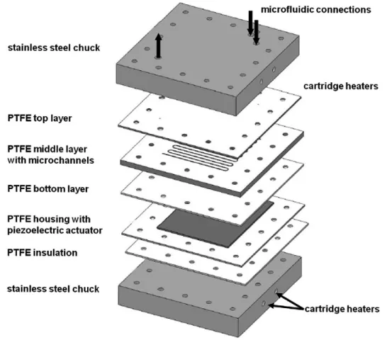
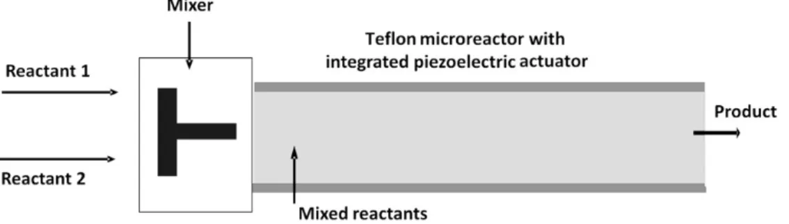
Continuous-flow precipitation of HAp was also carried out in a Teflon microreactor with integrated piezoelectric actuator developed at MIT (Massachusetts Institute of Technology) (Figure 2) [17]. The microreactor is made of Teflon (PTFE) plates, with an integrated piezoelectric element with a thickness of 1 mm. The channel width is 600 µm and the total volume is 1000 µL. The system has two inlets and one outlet. The microfluidic connections were provided by Teflon tubing (Upchurch Scientific) with 1.02 mm in inner diameter. Reactants were mixed in a T-mixer (same mixing chamber used in the tubular microreactor for the single-phase study) (Figure 3) before entering in the reactor, and thus only one inlet was used. As in the previous systems, the reactants were fed into the reactor by means of a syringe pump (Harvard PHD 2000), where syringes were kept at 37 ºC through the use of thermal jackets (Upchurch Scientific).
2.2. HAp precipitation
HAp was synthesized by the mixing of a saturated calcium hydroxide (Sigma-Aldrich, 95%) aqueous solution and an orthophosphoric acid (Mallinckrodt, 85%) aqueous solution at 37 ºC, with a mixing molar ratio Ca/P=1.33. This mixing molar ratio was defined in order to obtain the desired product, e.g. hydroxyapatite in conditions that promote the survival of cells, e.g. physiological conditions of pH and temperature. After several preliminary experiments we verified that with a mixing molar ratio Ca/P=1.33 we could obtain the desired product at near physiological conditions of pH and temperature.
0.5 L of both reactants was prepared with ultra-pure water (Milli Q water, resistivity of 18.2 MΩ/cm at 25 ºC) and their ionic force was adjusted by the addition of 6 mL of potassium chloride (Mallinckrodt, 99.8%) 4 M solution. To facilitate the dissolution of calcium hydroxide, the solution was agitated in a closed vessel for 24 hours at 500 rpm and at 25 ºC,
7
as its solubility decreases with temperature increase [18]. Then, both reactants were heated and kept at 37 ºC. The operating conditions used are presented in Table 1.
Temperature (J-KEM Scientific) and pH (needle-like tip micro pH electrode, Thermo Fisher Scientific ORION) were measured at different time intervals at the outlet of the microsystems. The pH electrode was calibrated with two buffer solutions with pH=7.00 and pH=10.00 at 25 ºC.
In a previous work [19], HAp precipitation was conducted in batch, in a 1L stirred tank, under the same conditions of reagents concentration, mixing Ca/P molar ratio and temperature. Carbonated HAp of B-type was synthesized, particles being collected after approximately 6 hours at a final pH close to 7. Results obtained in that work will be used for comparison.
2.3. HAp characterization
Samples were withdrawn at the outlet of the microreactors, centrifuged (at 1500 rpm for 5 min), washed twice with ultra pure water and conserved in ethanol (Koptec 200 proof pure), which stops the solid-liquid reaction [20]. For X-ray diffraction (XRD) (PanAlytical X’Pert PRO MPD), scanning electron microscopy (SEM) (FEI Quanta 400FEG ESEM/EDAX Genesis X4M, with an accelerating voltage of 20 kV) and transmission electron microscopy (TEM) (HR-(EF)TEM JEOL, 2200FS / EDS Oxford, INCA Energy TEM 250) studies, suspensions were dried at T=80 ºC during 24 h. For SEM analysis samples were covered by a 10 nm gold layer and for TEM analysis powders were suspended in ethanol and a small drop of the suspension was fixed on a support (Carbon film on 400 mesh, Monocomp). For Fourier transform infrared spectroscopy (FTIR) spectroscopy (Bruker Vertex 70 with MCT detector), a small drop of the suspension was put on a 1 mm thick ZnSe support, dried (80 ºC) to evaporate the ethanol and then
8
analyzed. Finally, for particle size distribution analysis, suspensions were collected at the end of each experiment and directly analyzed using a Malvern Mastersizer 2000 apparatus.
3. Results and discussion
3.1. Important parameters in the precipitation of HAp
In this work, experiments were conducted under near-physiological conditions of temperature and pH (Table 2), which is particularly important when preparing HAp for medical purposes. Indeed, it is important to follow specific criteria for pH and temperature in order to promote more conductive conditions for the survival of bone-related cells [15]. Furthermore, from a thermodynamic point of view, these conditions favour the precipitation of HAp, since at body temperature and pH between 4 and 12, HAp is the most stable calcium phosphate salt [21]. However, considering the kinetics it does not imply that HAp is the only calcium phosphate to precipitate [22]. Therefore, diluted solutions were used (Table 1) to obtain low supersaturations and promote the formation of a homogeneous solution of hydroxide and calcium ions, so allowing a better control over the reaction conditions [19].
The continuous use of ultrasound could explain the increase in the temperature (Table 2). In fact, ultrasonic waves produce heat when passed through a substance due to the transfer of ultrasonic energy, making the maintenance of isothermal conditions difficult in the systems used. The problem is magnified in the Teflon microreactor, not only because of the higher power input but also because of the smaller area of irradiation [23] as compared to the tubular microreactor immersed in the ultrasonic bath. In the case of the tubular microreactor, the emitted ultrasonic waves first need to cross the liquid inside the ultrasonic bath (e.g. water) before reaching the microreactor. Therefore, ultrasonication intensity
9
inside the microreactor is lower than expected. In the Teflon microreactor, the acoustic waveform is directly transmitted to the reactor, being thus energetically more efficient and further allowing for a precise control of the operating frequency [17]. Moreover, it should be noted that the precipitation reaction of HAp is exothermic, which also could explain the observed increase in the temperature (Table 2). Thereby, the factors mentioned above may contribute to the temperature increase. Although the temperature variation may influence the characteristics of the final product [24, 25], no significant differences in the studied parameters are expected given the small differences observed in the temperature increase (between 0.7 and 3.7 ºC).
3.2. Phase identification
Figure 4 displays XRD patterns of the products obtained in different systems (Tubular-SPF, Tubular-GLF 1, Tubular-GLF 2 and Teflon-SPF) and for a commercial HAp. XRD patterns were compared to a reference pattern (JCPDS 00-009-0432), indicating that the product formed is single-phased HAp for all the experimental conditions studied. XRD patterns of the particles obtained possess broader peaks than the commercial HAp, showing thus lower crystallinity. Peaks obtained at 28 º2θ and 40.5 º2θ are sharp and possess high intensity, which is characteristic of high crystallinity and large grain size. These peaks are assigned to potassium chloride and are mainly observed in samples Tubular-SPF, Tubular-GLF 1 and Tubular-GLF 2 patterns. This may be explained by the occlusion of KCl. Indeed, part of the mother liquor could have been trapped between the aggregates, and the KCl contained in the mother liquor crystallized at the drying step. As to sample Teflon-SPF, as smaller particles were formed, these hardly grew and thus did not allow the inclusion of impurities. In addition, results showed that more individualized particles were formed, e.g. more
10
primary particles, thus enabling removal of part of the mother liquor during the washing step.
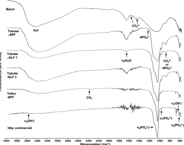
Based on peaks identified (Figure 5 and Table 3), the synthesis products have a typical apatite structure. Presence of adsorbed water in the products formed is also verified, since a broad band from approximately 3700 to 3000 cm-1 and a peak at 1643 cm-1 (bending mode,
υ2) are observed. This may be justified by the low drying temperature (80 ºC) and the
absence of a ripening (ageing) treatment [22, 26, 27]. As to the functional groups of HAp, characteristic bands of the phosphate group, PO43-, are exhibited in all the spectra, although
in some cases (Tubular-SPF) broad and unresolved. The peak assigned to the stretching mode, υs, (around 3571 cm-1) of the hydroxyl group, OH-, is weak in all the spectra, and the
peak assigned to itsvibrational mode, υL, (around 630 cm-1) is only visible in the spectrum of the commercial HAp. This may be due to an overlap with the broad peak of the adsorbed water [28]. Further, it is common to find substitution in the apatite structure, namely involving carbonate, CO32-, and hydrogen phosphate, HPO42-. From literature, peaks
located at 870 and 875 cm-1 can be attributed to the vibrational frequencies of carbonate
ions, which can indicate the formation of carbonated HAp [29]. Regarding the peaks associated to the HPO42- group, they are observed in all the spectra, which can be
associated with the formation of calcium-deficient HAp [30]. Therefore, HAp formed seems to present characteristics similar to biological apatites, as they generally are considered calcium-deficient carbonated apatites [15]. Information on the crystallinity is also available by IR spectroscopy. It can be seen that the product obtained in the Teflon microreactor (Teflon-SPF) is more crystalline when compared to the others precipitates, especially when observing the phosphate bands around 1000 cm-1, which are broad and
11
band corresponding to the adsorbed water (3700 to 3000 cm-1) is much smaller than the
other spectra. The noise observed in almost all the spectra and especially in the commercial HAp spectrum (1800 to 1400 cm-1) is due to water vapor.
3.3. Particle morphology, size and size distribution
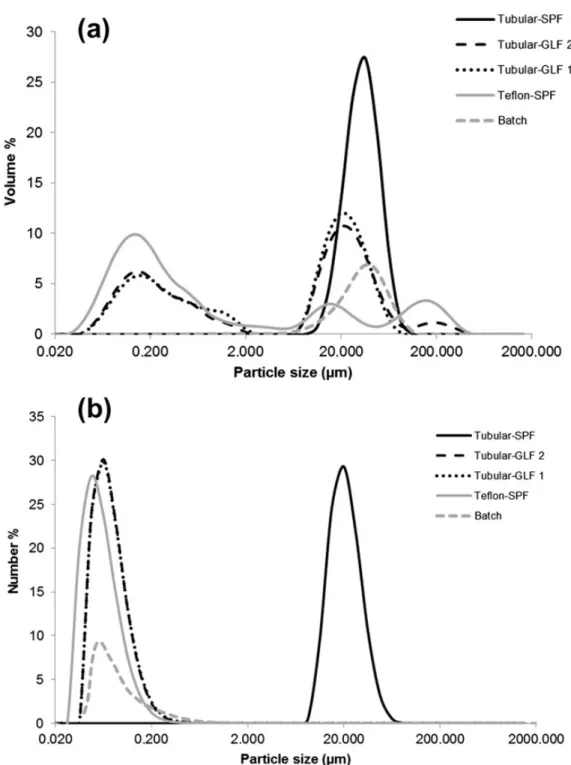
It was chosen to present particle size distribution results as both volume and number distributions, allowing thus to detect the presence of aggregates and to study the size of the majority of the particles, respectively. According to the volume distribution (Figure 6a and Table 4), there are significant differences in particles size distribution, depending on the reactor used. For the study conducted in the tubular microreactor, results show the formation of aggregates with a mean particle diameter (d50) of 38.30 µm in single-phase
flow, while for the gas-liquid flow experiments, Figure 6a shows a bimodal population with micrometric-size aggregates and particles of about 100 to 200 nm. Using gas to create a segmented flow results in the formation of small reacting entities separated from each other by gas bubbles, which reduces particle-to particle interactions, and thus the formation of aggregates [17]. Nevertheless, some aggregation occurs, possibly due to the small size of the particles and their amorphous state. The particles formed possess a high surface area to volume ratio, resulting in a high surface tension, which can be lowered by particles adhering to one another [12]. Moreover, the pH conditions could favour the formation of aggregates, since the isoelectric point (IEP) of HAp varies between 4 and 6 [32], which is close to the final pH of the suspension (Table 2). Regarding the product formed in the Teflon microreactor, it is mainly constituted by particles with sizes between 100 to 200 nm (Figure 6a). Larger aggregates with sizes around 100 µm, not observed in the tubular microreactor, are also present. This could be explained by the fact that smaller particles were formed in the Teflon reactor and have thus higher tendency to aggregate. Besides, by
12
reducing channel width and increasing the ultrasound power input, the probability of particles to collide and thereby to aggregate is higher [12]. Therefore, volume-based results show the formation of aggregates for the all experimental conditions studied. However, the particle size distribution in number (obtained from the conversion of the particle size distribution in volume) shows that most of the as-prepared particles are at the nanometer size (Figure 6b Table 4). Indeed, the median particle diameter (d50) is around 60 to 50 nm
for almost all the powders, except for the sample Tubular-SPF, which is characterized by micrometric-size particles.
SEM images (Figure 7a) show aggregated nano-size particles for all the operation conditions studied. The microstructure of the HAp particles was also observed by TEM analysis (Figure 8). Primary particles seem uniform in size and shape, presenting less than 100 nm in length and around 20 nm in width, and a rod-like shape.
The as-prepared particles present therefore interesting characteristics for biomedical applications. Actually, nanocrystalline HAp powders exhibit greater surface area [16] when compared to microscale HAp. Moreover, it is desirable that the HAp for use in implants be bioresorbable so that it can be replaced, over a period of time, with regenerated bone upon implantation. In this context, nanoparticles of HAp have shown higher rates of bioresorbability than micrometric HAp and close to biological apatite [33]. Further, the resorbability of HAp can be developed with improving its crystallinity degree similar to biological HAp (60–70%) [34].
13
3.4. Comparison of HAp particles prepared in a stirred tank batch reactor and in the microreactors
XRD and FTIR results (Figure 4 and Figure 5) show some differences between HAp particles formed in the microsystems and in a stirred tank batch reactor [19]. Particles obtained in batch appear to be less crystalline than the particles formed in the microreactors, since their XRD pattern and FTIR spectrum exhibit broader peaks (Figure 4 and Figure 5). Furthermore, bands attributed to carbonate ionsat approximately 1454, 1428 and 878 cm-1 are clearly observed in the spectrum of the particles obtained in batch
(Figure 5), indicating the formation of carbonated HAp of B-type [29]. As referred in Castro et al. (2012), presence of carbonate ions can be explained by the absorption of CO2
from air, once the reaction system was open to air. On the other hand, carbonate bands at approximately 1454 and 1428 cm-1 are not exhibited in the spectra of the HAp powders
formed in the microsystems. In this case, systems were not open to air and carbonate ions could only come from the water used in the preparation of the reagents. Regarding particle size distribution, one can verify that particle aggregation was significantly reduced in the segmented-flow tubular microreactor and especially in the Teflon microreactor (Figure 6a). Further, smaller primary particles were obtained in the Teflon microreactor (Figure 6b). Regarding morphology and size of the HAp particles, in all the reactors rod-like shape nanoparticleswere formed (Figure 7a and b and Figure 8).
4. Conclusion
Continuous-flow precipitation of HAp was studied in two ultrasonic microreactors, a tubular microreactor immersed in an ultrasonic bath and a Teflon microreactor with integrated piezoelectric actuator. The as-prepared particles, irrespective of the system used,
14
consisted of nano-size calcium-deficient carbonated HAp particles, thus approaching biological apatites. Moreover, particles were obtained under near-physiological conditions of pH and temperature, making them promising compounds for bone substitution application.
Several configurations were tested in the tubular microreactor (single-phase flow and gas-liquid flow), and segmentation of the flow was successful in reducing particle aggregation. Control of aggregation was however best achieved in the Teflon microreactor, primarily due to the higher intensity of the ultrasound.
Synthesis products were also compared to the product obtained in a stirred tank batch reactor. The HAp particles formed have proved to be more crystalline and less carbonate contaminated than the HAp particles produced in the batch reactor. Moreover, microreactors used yielded HAp particles in a very short time and at a constant pH. Finally, particle aggregation and primary particle size were significantly reduced in the segmented-flow tubular microreactor and especially in the Teflon microreactor.
Acknowledgments
This work was supported by the Portuguese Foundation for Science and Technology (SFRH/BD/42992/2008) through the MIT-Portugal Program, Bioengineering Systems Focus Area. The authors are thankful to Dr. Speakman for his help with the X-ray
measurements and with the interpretation of the results.S.K. acknowledges funding from
15
References
[1] S. Bose, S.K. Saha, Synthesis and Characterization of Hydroxyapatite Nanopowders by Emulsion Technique, Chemistry of Materials, 15 (2003) 4464-4469.
[2] Q.-A. Wang, J.-X. Wang, M. Li, L. Shao, J.-F. Chen, L. Gu, Y.-T. An, Large-scale preparation of barium sulphate nanoparticles in a high-throughput tube-in-tube microchannel reactor, Chemical Engineering Journal, 149 (2009) 473-478.
[3] D. Jeevarathinam, A.K. Gupta, B. Pitchumani, R. Mohan, Effect of gas and liquid flowrates on the size distribution of barium sulfate nanoparticles precipitated in a two phase flow capillary microreactor, Chemical Engineering Journal, 173 (2011) 607-611.
[4] L.-H. Hung, A.P. Lee, Microfluidic Devices for the Synthesis of Nanoparticles and Biomaterials, Journal of Medical and Biological Engineering, 27 (2007).
[5] J. Leng, J.-B. Salmon, Microfluidic crystallization, Lab on a chip, 9 (2009) 24-34. [6] Y. Song, J. Hormes, C.S.S.R. Kumar, Microfluidic Synthesis of Nanomaterials, Small, 4 (2008) 698-711.
[7] S. Marre, K.F. Jensen, Synthesis of micro and nanostructures in microfluidic systems, Chemical Society Reviews, 39 (2010) 1183-1202.
[8] C.-X. Zhao, L. He, S.Z. Qiao, A.P.J. Middelberg, Nanoparticle synthesis in microreactors, Chemical Engineering Science, 66 (2011) 1463-1479.
[9] S.L. Poe, M.A. Cummings, M.P. Haaf, D.T. McQuade, Solving the Clogging Problem: Precipitate-Forming Reactions in Flow, Angewandte Chemie International Edition, 45 (2006) 1544-1548.
[10] A. Gunther, K.F. Jensen, Multiphase microfluidics: from flow characteristics to chemical and materials synthesis, Lab on a chip, 6 (2006) 1487-1503.
16
[11] S.A. Khan, K.F. Jensen, Microfluidic Synthesis of Titania Shells on Colloidal Silica, Advanced Materials, 19 (2007) 2556-2560.
[12] M.D. Luque de Castro, F. Priego-Capote, Ultrasound-assisted crystallization (sonocrystallization), Ultrasonics Sonochemistry, 14 (2007) 717-724.
[13] M.P. Ferraz, F.J. Monteiro, C.M. Manuel, Hydroxyapatite nanoparticles: A review of preparation methodologies, Journal of Applied Biomaterials & Biomechanics 2(2004) 74-80.
[14] Q. He, Z. Huang, Y. Liu, W. Chen, T. Xu, Template-directed one-step synthesis of flowerlike porous carbonated hydroxyapatite spheres, Materials Letters, 61 (2007) 141-143. [15] P.N. Kumta, C. Sfeir, D.-H. Lee, D. Olton, D. Choi, Nanostructured calcium phosphates for biomedical applications: novel synthesis and characterization, Acta Biomaterialia, 1 (2005) 65-83.
[16] I. Mobasherpour, M.S. Heshajin, A. Kazemzadeh, M. Zakeri, Synthesis of nanocrystalline hydroxyapatite by using precipitation method, Journal of Alloys and Compounds, 430 (2007) 330-333.
[17] S. Kuhn, T. Noel, L. Gu, P.L. Heider, K.F. Jensen, A Teflon microreactor with integrated piezoelectric actuator to handle solid forming reactions, Lab on a chip, 11 (2011) 2488-2492.
[18] K. Johannsen, S. Rademacher, Modelling the kinetics of calcium hydroxide dissolution in water, Crystal Research and Technology 27 (1999) 72-78.
[19] F. Castro, A. Ferreira, F. Rocha, A. Vicente, J. António Teixeira, Characterization of intermediate stages in the precipitation of hydroxyapatite at 37 °C, Chemical Engineering Science.
17
[20] L. Bernard, M. Freche, J.L. Lacout, B. Biscans, Modeling of the dissolution of calcium hydroxyde in the preparation of hydroxyapatite by neutralization, Chemical Engineering Science, 55 (2000) 5683-5692.
[21] Elliot J.C., Structure and chemistry of the apatites and other calcium orthophosphates, Elsevier, Amsterdam, 1994.
[22] S. Koutsopoulos, Synthesis and characterization of hydroxyapatite crystals: A review study on the analytical methods, Journal of Biomedical Materials Research, 62 (2002) 600-612.
[23] Pankaj, M. Ashokkumar, Theoretical and experimental sonochemistry involving inorganic systems, Springer, New York, 2010.
[24] M.A. Martins, C. Santos, M.M. Almeida, M.E.V. Costa, Hydroxyapatite micro- and nanoparticles: Nucleation and growth mechanisms in the presence of citrate species, Journal of Colloid and Interface Science, 318 (2008) 210-216.
[25] P.G. Koutsoukos, Current Knowledge of Calcium Phosphate Chemistry and in Particular Solid Surface-Water Interface Interactions, in: Proceedings of the Second International Conference on Phosphorus Recovery for Recycling from Sewage and Animal wastes Institute of chemical engineering and high temperature chemical processes, Univ. of Patras, 2000, pp. 12-14.
[26] A. Osaka, Y. Miura, K. Takeuchi, M. Asada, K. Takahashi, Calcium apatite prepared from calcium hydroxide and orthophosphoric acid, Journal of Materials Science: Materials in Medicine, 2 (1991) 51-55.
[27] W. Zhou, M. Wang, W. Cheung, B. Guo, D. Jia, Synthesis of carbonated hydroxyapatite nanospheres through nanoemulsion, Journal of Materials Science: Materials in Medicine, 19 (2008) 103-110.
18
[28] M.-G. Ma, J.-F. Zhu, Solvothermal Synthesis and Characterization of Hierarchically Nanostructured Hydroxyapatite Hollow Spheres, European Journal of Inorganic Chemistry, 2009 (2009) 5522-5526.
[29] E. Landi, G. Celotti, G. Logroscino, A. Tampieri, Carbonated hydroxyapatite as bone substitute, Journal of the European Ceramic Society, 23 (2003) 2931-2937.
[30] S. Meejoo, W. Maneeprakorn, P. Winotai, Phase and thermal stability of nanocrystalline hydroxyapatite prepared via microwave heating, Thermochimica Acta, 447 (2006) 115-120.
[31] D. Tadic, F. Peters, M. Epple, Continuous synthesis of amorphous carbonated apatites, Biomaterials, 23 (2002) 2553-2559.
[32] E. Bouyer, F. Gitzhofer, M.I. Boulos, Morphological study of hydroxyapatite nanocrystal suspension, Journal of Materials Science: Materials in Medicine, 11 (2000) 523-531.
[33] R. Murugan, S. Ramakrishna, Aqueous mediated synthesis of bioresorbable nanocrystalline hydroxyapatite, Journal of Crystal Growth, 274 (2005) 209-213.
[34] M.H. Fathi, A. Hanifi, V. Mortazavi, Preparation and bioactivity evaluation of bone-like hydroxyapatite nanopowder, Journal of Materials Processing Technology, 202 (2008) 536-542.
19
Figure and Tables
Figure 1. Schematic representation of a) the single-phase flow tubular reactor, b) the
gas-liquid flow tubular reactor and c) picture of the gas-gas-liquid flow tubular reactor section. support, dried (80!C) to evaporate the ethanol and then analyzed.
Finally, for particle size distribution analysis, suspensions were col-lected at the end of each experiment and directly analyzed using a Malvern Mastersizer 2000 apparatus.
3. Results and discussion
3.1. Important parameters in the precipitation of HAp
In this work, experiments were conducted under near-physio-logical conditions of temperature and pH (Table 2), which is partic-ularly important when preparing HAp for medical purposes. Indeed, it is important to follow specific criteria for pH and temperature in order to promote more conductive conditions for the survival of bone-related cells [15]. Furthermore, from a
thermodynamic point of view, these conditions favor the precipita-tion of HAp, since at body temperature and pH between 4 and 12, HAp is the most stable calcium phosphate salt[21]. However, con-sidering the kinetics it does not imply that HAp is the only calcium phosphate to precipitate [22]. Therefore, diluted solutions were used (Table 1) to obtain low supersaturation and promote the for-mation of a homogeneous solution of hydroxide and calcium ions, so allowing a better control over the reaction conditions[19].
The continuous use of ultrasound could explain the increase in the temperature (Table 2). In fact, ultrasonic waves produce heat when passed through a substance due to the transfer of ultrasonic energy, making the maintenance of isothermal conditions difficult in the systems used. The problem is magnified in the Teflon mic-roreactor, not only because of the higher power input but also be-cause of the smaller area of irradiation[23] as compared to the tubular microreactor immersed in the ultrasonic bath. In the case
Fig. 1. Schematic representation of (a) the single-phase flow tubular reactor, (b) the gas–liquid flow tubular reactor and (c) picture of the gas–liquid flow tubular reactor section.
F. Castro et al. / Chemical Engineering Journal xxx (2012) xxx–xxx 3
Please cite this article in press as: F. Castro et al., Continuous-flow precipitation of hydroxyapatite in ultrasonic microsystems, Chem. Eng. J. (2012),http:// dx.doi.org/10.1016/j.cej.2012.11.014
20
Figure 2. CAD representation of the microreactor assembly: The microreactor consists of 3
PTFE plates, with the middle layer providing the microchannel structure, and the top layer the inlet and outlet holes. The piezoelectric actuator is integrated using PTFE housing for mechanical stability and a PTFE layer for electrical insulation. These plates are compressed using two stainless steel chucks, with holes for the insertion of cartridge heaters, and the top chuck providing the microfluidic connections [17] - Reproduced by permission of The Royal Society of Chemistry.
of the tubular microreactor, the emitted ultrasonic waves first need to cross the liquid inside the ultrasonic bath (e.g. water) before reaching the microreactor. Therefore, ultrasonication intensity in-side the microreactor is lower than expected. In the Teflon mic-roreactor, the acoustic waveform is directly transmitted to the reactor, being thus energetically more efficient and further allow-ing for a precise control of the operatallow-ing frequency[17]. Moreover, it should be noted that the precipitation reaction of HAp is exother-mic, which also could explain the observed increase in the
temper-ature (Table 2). Thereby, the factors mentioned above may
contribute to the temperature increase. Although the temperature variation may influence the characteristics of the final product
[24,25], no significant differences in the studied parameters are ex-pected given the small differences observed in the temperature in-crease (between 0.7 and 3.7!C).
3.2. Phase identification
Fig. 4displays XRD patterns of the products obtained in differ-ent systems (Tubular-SPF, Tubular-GLF 1, Tubular-GLF 2 and
Tef-Fig. 2. CAD representation of the microreactor assembly: the microreactor consists of three PTFE plates, with the middle layer providing the microchannel structure, and the top layer the inlet and outlet holes. The piezoelectric actuator is integrated using PTFE housing for mechanical stability and a PTFE layer for electrical insulation. These plates are compressed using two stainless steel chucks, with holes for the insertion of cartridge heaters, and the top chuck providing the microfluidic connections[17]– reproduced by permission of The Royal Society of Chemistry.
Fig. 3. Schematic representation of the Teflon microreactor with integrated piezoelectric actuator.
Table 1
Operating conditions for the continuous-flow precipitation of HAp.
Reactants Tubular microreactor Teflon microreactor with integrated piezoelectric actuator [Ca(OH)2]
(mM)
[H3PO4]
(mM)
Liquid flow rate (mL/min)
Gas flow rate (standard mL/min)
Liquid residence times(min)
Ultrasound frequency and power input
Liquid flow rate (mL/min)
Liquid residence times(min)
Ultrasound frequency and power input 19.3 14.5 2.0 – 0.30 40 kHz and 4–8 W 3.3 0.30 50 kHz and 30 W
2.0 1.2 0.19 2.0 2.0 0.15
4 F. Castro et al. / Chemical Engineering Journal xxx (2012) xxx–xxx
Please cite this article in press as: F. Castro et al., Continuous-flow precipitation of hydroxyapatite in ultrasonic microsystems, Chem. Eng. J. (2012),http:// dx.doi.org/10.1016/j.cej.2012.11.014
21
Figure 3. Schematic representation of the Teflon microreactor with integrated piezoelectric
actuator.
of the tubular microreactor, the emitted ultrasonic waves first need to cross the liquid inside the ultrasonic bath (e.g. water) before reaching the microreactor. Therefore, ultrasonication intensity in-side the microreactor is lower than expected. In the Teflon mic-roreactor, the acoustic waveform is directly transmitted to the reactor, being thus energetically more efficient and further allow-ing for a precise control of the operatallow-ing frequency[17]. Moreover, it should be noted that the precipitation reaction of HAp is exother-mic, which also could explain the observed increase in the temper-ature (Table 2). Thereby, the factors mentioned above may
contribute to the temperature increase. Although the temperature variation may influence the characteristics of the final product
[24,25], no significant differences in the studied parameters are ex-pected given the small differences observed in the temperature in-crease (between 0.7 and 3.7!C).
3.2. Phase identification
Fig. 4displays XRD patterns of the products obtained in differ-ent systems (Tubular-SPF, Tubular-GLF 1, Tubular-GLF 2 and
Tef-Fig. 2. CAD representation of the microreactor assembly: the microreactor consists of three PTFE plates, with the middle layer providing the microchannel structure, and the top layer the inlet and outlet holes. The piezoelectric actuator is integrated using PTFE housing for mechanical stability and a PTFE layer for electrical insulation. These plates are compressed using two stainless steel chucks, with holes for the insertion of cartridge heaters, and the top chuck providing the microfluidic connections[17]– reproduced by permission of The Royal Society of Chemistry.
Fig. 3. Schematic representation of the Teflon microreactor with integrated piezoelectric actuator.
Table 1
Operating conditions for the continuous-flow precipitation of HAp.
Reactants Tubular microreactor Teflon microreactor with integrated piezoelectric actuator [Ca(OH)2]
(mM)
[H3PO4]
(mM)
Liquid flow rate (mL/min)
Gas flow rate (standard mL/min)
Liquid residence times(min)
Ultrasound frequency and power input
Liquid flow rate (mL/min)
Liquid residence times(min)
Ultrasound frequency and power input 19.3 14.5 2.0 – 0.30 40 kHz and 4–8 W 3.3 0.30 50 kHz and 30 W
2.0 1.2 0.19 2.0 2.0 0.15
4 F. Castro et al. / Chemical Engineering Journal xxx (2012) xxx–xxx
Please cite this article in press as: F. Castro et al., Continuous-flow precipitation of hydroxyapatite in ultrasonic microsystems, Chem. Eng. J. (2012),http:// dx.doi.org/10.1016/j.cej.2012.11.014
22
Figure 4. XRD patterns of the HAp particles produced in different reactors. lon-SPF) and for a commercial HAp. XRD patterns were compared
to a reference pattern (JCPDS 00-009-0432), indicating that the product formed is single-phased HAp for all the experimental conditions studied. XRD patterns of the particles obtained possess broader peaks than the commercial HAp, showing thus lower crystallinity. Peaks obtained at 28! 2h and 40.5! 2h are sharp and possess high intensity, which is characteristic of high crystallinity and large grain size. These peaks are assigned to potassium chloride and are mainly observed in samples Tubular-SPF, Tubular-GLF 1 and Tubular-GLF 2 patterns. This may be explained by the occlusion of KCl. Indeed, part of the mother liquor could have been trapped between the aggregates, and the KCl contained in the mother liquor crystallized at the drying step.
Based on peaks identified (Fig. 5 andTable 3), the synthesis products have a typical apatite structure. Presence of adsorbed water in the products formed is also verified, since a broad band from approximately 3700–3000 cm!1 and a peak at 1643 cm!1
(bending mode, m2) are observed. This may be justified by the
low drying temperature (80!C) and the absence of a ripening (aging) treatment[22,26,27]. As to the functional groups of HAp, characteristic bands of the phosphate group, PO3!
4 , are exhibited
in all the spectra, although in some cases (Tubular-SPF) broad and unresolved. The peak assigned to the stretching mode, mS,
(around 3571 cm!1) of the hydroxyl group, OH!, is weak in all
the spectra, and the peak assigned to its vibrational mode, mL,
(around 630 cm!1) is only visible in the spectrum of the
commer-cial HAp. This may be due to an overlap with the broad peak of the adsorbed water[28]. Further, it is common to find substitution in the apatite structure, namely involving carbonate, CO2!
3 , and
hydrogen phosphate, HPO2!
4 . From literature, peaks located at
870 and 875 cm!1can be attributed to the vibrational frequencies
of carbonate ions, which can indicate the formation of carbonated HAp[29]. Regarding the peaks associated to the HPO2!
4 group, they
are observed in all the spectra, which can be associated with the formation of calcium-deficient HAp [30]. Therefore, HAp formed seems to present characteristics similar to biological apatites, as they generally are considered calcium-deficient carbonated apa-tites[15]. Information on the crystallinity is also available by IR spectroscopy. It can be seen that the product obtained in the Teflon microreactor (Teflon-SPF) is more crystalline when compared to the others precipitates, especially when observing the phosphate bands around 1000 cm!1, which are broad and unresolved in the
other samples, indicating poor crystallinity [31]. Moreover, the broad band corresponding to the adsorbed water (3700– 3000 cm!1) is much smaller than the other spectra.
The noise observed in almost all the spectra and especially in the commercial HAp spectrum (1800–1400 cm!1) is due to water
vapor.
Table 2
Parameters measured during continuous-flow precipitation of HAp.
Sample Flow type Liquid residence times(min)
pH (average) Precipitate (mg/mL)
Initial T
(!C) Final T(!C) Tubular microreactor Tubular-SPF Single-phase flow 0.30 7.24 ± 0.12 1.13 ± 0.09 38.0
Tubular-GLF 1 Gas–liquid flow 0.19 7.25 ± 0.35 1.20 ± 0.10 37.0 37.7 Tubular-GLF 2 Gas–liquid flow 0.15 7.04 ± 0.21 1.22 ± 0.10 37.0 Teflon microreactor with integrated
piezoelectric actuator
Teflon-SPF Single-phase flow 0.30 7.23 ± 0.20 1.39 ± 0.12 38.3 42.0
Stirred tank Batch Batch 330 6.90a 0.91 ± 0.02 36.7 37.9
apH value corresponds to the final value.
Fig. 4. XRD patterns of the HAp particles produced in different reactors.
F. Castro et al. / Chemical Engineering Journal xxx (2012) xxx–xxx 5
Please cite this article in press as: F. Castro et al., Continuous-flow precipitation of hydroxyapatite in ultrasonic microsystems, Chem. Eng. J. (2012),http:// dx.doi.org/10.1016/j.cej.2012.11.014
23
Figure 5. FTIR spectra of the HAp particles produced in different reactors.
3.3. Particle morphology, size and size distribution
It was chosen to present particle size distribution results as both volume and number distributions, allowing thus to detect the presence of aggregates and to study the size of the majority of the particles, respectively. According to the volume distribution (Fig. 6a andTable 4), there are significant differences in particles size distribution, depending on the reactor used. For the study con-ducted in the tubular microreactor, results show the formation of aggregates with a mean particle diameter (d50) of 38.30lm in
sin-gle-phase flow, while for the gas–liquid flow experiments,Fig. 6a shows a bimodal population with micrometric-size aggregates and particles of about 100–200 nm. Using gas to create a seg-mented flow results in the formation of small reacting entities sep-arated from each other by gas bubbles, which reduces particle-to
particle interactions, and thus the formation of aggregates[17]. Nevertheless, some aggregation occurs, possibly due to the small size of the particles and their amorphous state. The particles formed possess a high surface area to volume ratio, resulting in a high surface tension, which can be lowered by particles adhering to one another[12]. Moreover, the pH conditions could favor the formation of aggregates, since the isoelectric point (IEP) of HAp varies between 4 and 6[32], which is close to the final pH of the suspension (Table 2). Regarding the product formed in the Teflon microreactor, it is mainly constituted by particles with sizes be-tween 100 and 200 nm (Fig. 6a). Larger aggregates with sizes around 100lm, not observed in the tubular microreactor, are also present. This could be explained by the fact that smaller particles were formed in the Teflon reactor and have thus higher tendency to aggregate. Besides, by reducing channel width and increasing Fig. 5. FTIR spectra of the HAp particles produced in different reactors.
Table 3
FTIR bands of HAp powders.
Groups Wavenumber (cm!1)
HAp commercial Tubular-SPF Tubular-GLF 1 Tubular-GLF 2 Teflon-SPF Batch mS(OH!);mL(OH!) 3571; 630 3565 3566 3565 3566 3570
m1ðPO3!4 Þ; m3ðPO34Þ; m4ðPO3!4 Þ 962; 1037; 603 961; 1027; 601 962; 1031; 602 961; 1029; 602 962; 1029; 600 Approximately at 961
a; 1029; 600 m1ðCO2!3 Þ; m3orm4ðCO2!3 Þ 1454; 1428 m2ðCO2!3 Þ; HPO2!4 871 872 872 871 874 HPO2! 4 1215 1215 HOH Around 1643b 3000–3700; 1643
aBroadening of the peaks assigned to PO3!
4 , thus leading to difficulties in peak identification. bPeaks assigned to HOH in the commercial HAp are due to the water present in the atmosphere.
6 F. Castro et al. / Chemical Engineering Journal xxx (2012) xxx–xxx
Please cite this article in press as: F. Castro et al., Continuous-flow precipitation of hydroxyapatite in ultrasonic microsystems, Chem. Eng. J. (2012),http:// dx.doi.org/10.1016/j.cej.2012.11.014
24
Figure 6. a) Size distribution in volume of the HAp particles produced in different reactors
and b) size distribution in number of the HAp particles produced in different reactors.
the ultrasound power input, the probability of particles to collide
and thereby to aggregate is higher [12]. Therefore, volume-based
results show the formation of aggregates for the all experimental conditions studied. However, the particle size distribution in num-ber (obtained from the conversion of the particle size distribution in volume) shows that most of the as-prepared particles are at the
nanometer size (Fig. 6b and Table 4). Indeed, the median particle
diameter (d50) is around 60–50 nm for almost all the powders,
ex-cept for the sample Tubular-SPF, which is characterized by micro-metric-size particles.
SEM images (Fig. 7a) show aggregated nano-size particles for all
the operation conditions studied. The microstructure of the HAp
particles was also observed by TEM analysis (Fig. 8). Primary
particles seem uniform in size and shape, presenting less than 100 nm in length and around 20 nm in width, and a rod-like shape.
The as-prepared particles present therefore interesting charac-teristics for biomedical applications. Actually, nanocrystalline
HAp powders exhibit greater surface area[16] when compared to
microscale HAp. Moreover, it is desirable that the HAp for use in implants be bioresorbable so that it can be replaced, over a period of time, with regenerated bone upon implantation. In this context, nanoparticles of HAp have shown higher rates of bioresorbability
than micrometric HAp, and close to biological apatite[33]. Further,
the resorbability of HAp can be developed with improving its
crystallinity degree similar to biological HAp (60–70%) [34].
Fig. 6. (a) Size distribution in volume of the HAp particles produced in different reactors and (b) size distribution in number of the HAp particles produced in different reactors.
Table 4
Parameters of the particle size distribution of HAp powders produced in the
microreactors. d10: 10% of the particles are smaller than this value, d50: median
particle diameter; d90: 90% of the particles are smaller than this value.
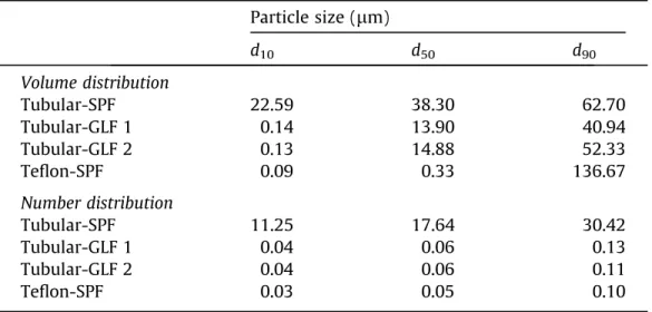
Particle size (lm) d10 d50 d90 Volume distribution Tubular-SPF 22.59 38.30 62.70 Tubular-GLF 1 0.14 13.90 40.94 Tubular-GLF 2 0.13 14.88 52.33 Teflon-SPF 0.09 0.33 136.67 Number distribution Tubular-SPF 11.25 17.64 30.42 Tubular-GLF 1 0.04 0.06 0.13 Tubular-GLF 2 0.04 0.06 0.11 Teflon-SPF 0.03 0.05 0.10
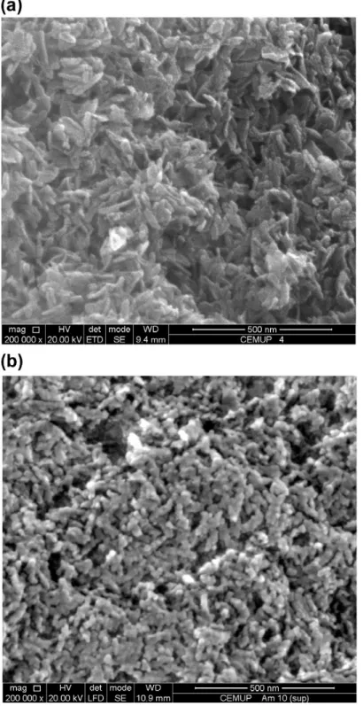
Fig. 7. (a) SEM image of the HAp particles produced in the microreactors and (b) SEM image of the HAp particles produced in a stirred tank batch reactor.
F. Castro et al. / Chemical Engineering Journal xxx (2012) xxx–xxx 7
Please cite this article in press as: F. Castro et al., Continuous-flow precipitation of hydroxyapatite in ultrasonic microsystems, Chem. Eng. J. (2012),http:// dx.doi.org/10.1016/j.cej.2012.11.014
25
Figure 7. a) SEM image of the HAp particles produced in the microreactors and b) SEM
image of the HAp particles produced in a stirred tank batch reactor.
the ultrasound power input, the probability of particles to collide and thereby to aggregate is higher[12]. Therefore, volume-based results show the formation of aggregates for the all experimental conditions studied. However, the particle size distribution in num-ber (obtained from the conversion of the particle size distribution in volume) shows that most of the as-prepared particles are at the nanometer size (Fig. 6b andTable 4). Indeed, the median particle diameter (d50) is around 60–50 nm for almost all the powders,
ex-cept for the sample Tubular-SPF, which is characterized by micro-metric-size particles.
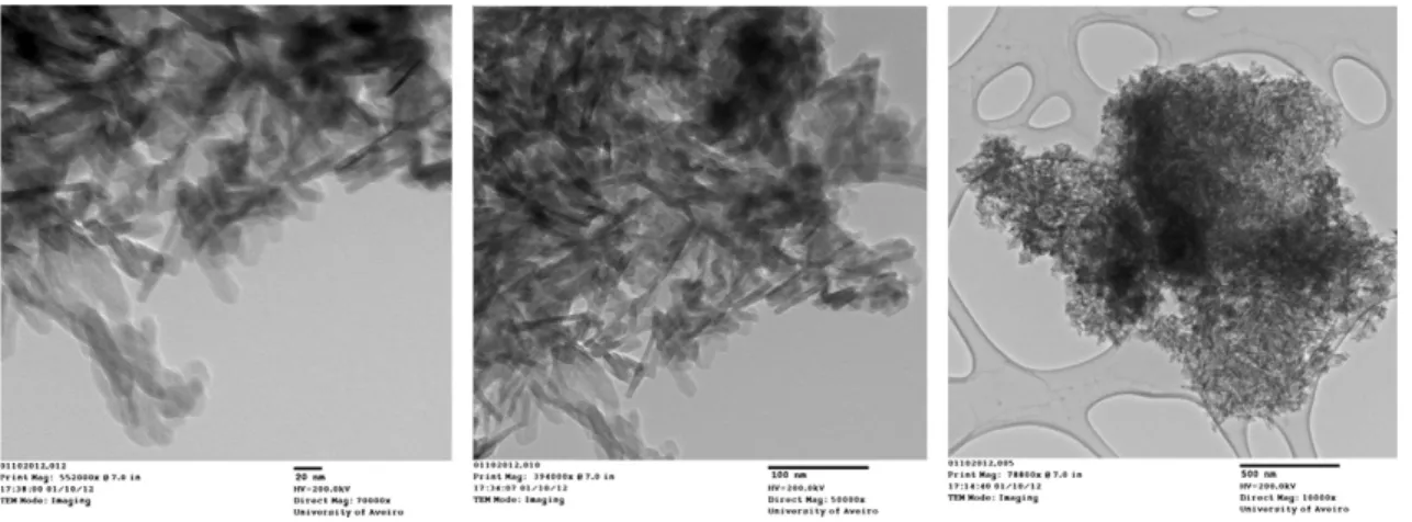
SEM images (Fig. 7a) show aggregated nano-size particles for all the operation conditions studied. The microstructure of the HAp particles was also observed by TEM analysis (Fig. 8). Primary particles seem uniform in size and shape, presenting less than 100 nm in length and around 20 nm in width, and a rod-like shape.
The as-prepared particles present therefore interesting charac-teristics for biomedical applications. Actually, nanocrystalline HAp powders exhibit greater surface area[16]when compared to microscale HAp. Moreover, it is desirable that the HAp for use in implants be bioresorbable so that it can be replaced, over a period of time, with regenerated bone upon implantation. In this context, nanoparticles of HAp have shown higher rates of bioresorbability than micrometric HAp, and close to biological apatite[33]. Further, the resorbability of HAp can be developed with improving its crystallinity degree similar to biological HAp (60–70%)[34].
Fig. 6. (a) Size distribution in volume of the HAp particles produced in different reactors and (b) size distribution in number of the HAp particles produced in different reactors.
Table 4
Parameters of the particle size distribution of HAp powders produced in the microreactors. d10: 10% of the particles are smaller than this value, d50: median
particle diameter; d90: 90% of the particles are smaller than this value.
Particle size (lm) d10 d50 d90 Volume distribution Tubular-SPF 22.59 38.30 62.70 Tubular-GLF 1 0.14 13.90 40.94 Tubular-GLF 2 0.13 14.88 52.33 Teflon-SPF 0.09 0.33 136.67 Number distribution Tubular-SPF 11.25 17.64 30.42 Tubular-GLF 1 0.04 0.06 0.13 Tubular-GLF 2 0.04 0.06 0.11 Teflon-SPF 0.03 0.05 0.10
Fig. 7. (a) SEM image of the HAp particles produced in the microreactors and (b) SEM image of the HAp particles produced in a stirred tank batch reactor. F. Castro et al. / Chemical Engineering Journal xxx (2012) xxx–xxx 7
Please cite this article in press as: F. Castro et al., Continuous-flow precipitation of hydroxyapatite in ultrasonic microsystems, Chem. Eng. J. (2012),http:// dx.doi.org/10.1016/j.cej.2012.11.014
26
Figure 8. TEM images of the HAp particles produced in the microreactors.
3.4. Comparison of HAp particles prepared in a stirred tank batch reactor and in the microreactors
XRD and FTIR results (Figs. 4 and 5) show some differences be-tween HAp particles formed in the microsystems and in a stirred tank batch reactor[19]. Particles obtained in batch appear to be less crystalline than the particles formed in the microreactors, since their XRD pattern and FTIR spectrum exhibit broader peaks (Figs. 4 and 5). Furthermore, bands attributed to carbonate ions at approximately 1454, 1428 and 878 cm!1are clearly observed
in the spectrum of the particles obtained in batch (Fig. 5), indicat-ing the formation of carbonated HAp of B-type[29]. As referred in Castro et al. (2012), presence of carbonate ions can be explained by the absorption of CO2from air, once the reaction system was open
to air. On the other hand, carbonate bands at approximately 1454 and 1428 cm!1are not exhibited in the spectra of the HAp powders
formed in the microsystems. In this case, systems were not open to air and carbonate ions could only come from the water used in the preparation of the reagents. Regarding particle size distribution one can verify that particle aggregation was significantly reduced in the segmented-flow tubular microreactor and especially in the Teflon microreactor (Fig. 6a). Further, smaller primary particles were obtained in the Teflon microreactor (Fig. 6b). Regarding mor-phology and size of the HAp particles, in all the reactors rod-like shape nanoparticles were formed (Figs.7a, b and8).
4. Conclusion
Continuous-flow precipitation of HAp was studied in two sonic microreactors, a tubular microreactor immersed in an ultra-sonic bath and a Teflon microreactor with integrated piezoelectric actuator. The as-prepared particles, irrespective of the system used, consisted of nano-size calcium-deficient carbonated HAp particles, thus approaching biological apatites. Moreover, particles were obtained under near-physiological conditions of pH and tem-perature, making them promising compounds for bone substitu-tion applicasubstitu-tion.
Several configurations were tested in the tubular microreactor (single-phase flow and gas–liquid flow), and segmentation of the flow was successful in reducing particle aggregation. Control of aggregation was however best achieved in the Teflon microreactor, primarily due to the higher intensity of the ultrasound.
Synthesis products were also compared to the product obtained in a stirred tank batch reactor. The HAp particles formed have proved to be more crystalline and less carbonate contaminated
than the HAp particles produced in the batch reactor. Moreover, microreactors used yielded HAp particles in a very short time and at a constant pH. Finally, particle aggregation and primary par-ticle size were significantly reduced in the segmented-flow tubular microreactor and especially in the Teflon microreactor.
Acknowledgments
This work was supported by the Portuguese Foundation for Sci-ence and Technology (SFRH/BD/42992/2008) through the MIT-Por-tugal Program, Bioengineering Systems Focus Area. The authors are thankful to Dr. Speakman for his help with the X-ray measure-ments and with the interpretation of the results. S.K. acknowledges funding from the Swiss National Science Foundation (SNF).
References
[1] S. Bose, S.K. Saha, Synthesis and characterization of hydroxyapatite nanopowders by emulsion technique, Chem. Mater. 15 (2003) 4464–4469. [2] Q.-A. Wang, J.-X. Wang, M. Li, L. Shao, J.-F. Chen, L. Gu, Y.-T. An, Large-scale
preparation of barium sulphate nanoparticles in a high-throughput tube-in-tube microchannel reactor, Chem. Eng. J. 149 (2009) 473–478.
[3] D. Jeevarathinam, A.K. Gupta, B. Pitchumani, R. Mohan, Effect of gas and liquid flowrates on the size distribution of barium sulfate nanoparticles precipitated in a two phase flow capillary microreactor, Chem. Eng. J. 173 (2011) 607–611. [4] L.-H. Hung, A.P. Lee, Microfluidic devices for the synthesis of nanoparticles and
biomaterials, J. Med. Biol. Eng. 27 (2007).
[5] J. Leng, J.-B. Salmon, Microfluidic crystallization, Lab Chip 9 (2009) 24–34. [6] Y. Song, J. Hormes, C.S.S.R. Kumar, Microfluidic synthesis of nanomaterials,
Small 4 (2008) 698–711.
[7] S. Marre, K.F. Jensen, Synthesis of micro and nanostructures in microfluidic systems, Chem. Soc. Rev. 39 (2010) 1183–1202.
[8] C.-X. Zhao, L. He, S.Z. Qiao, A.P.J. Middelberg, Nanoparticle synthesis in microreactors, Chem. Eng. Sci. 66 (2011) 1463–1479.
[9] S.L. Poe, M.A. Cummings, M.P. Haaf, D.T. McQuade, Solving the clogging problem: precipitate-forming reactions in flow, Angew. Chem. Int. Ed. 45 (2006) 1544–1548.
[10] A. Gunther, K.F. Jensen, Multiphase microfluidics: from flow characteristics to chemical and materials synthesis, Lab Chip 6 (2006) 1487–1503. [11] S.A. Khan, K.F. Jensen, Microfluidic synthesis of titania shells on colloidal silica,
Adv. Mater. 19 (2007) 2556–2560.
[12] M.D. Luque de Castro, F. Priego-Capote, Ultrasound-assisted crystallization (sonocrystallization), Ultrason. Sonochem. 14 (2007) 717–724.
[13] M.P. Ferraz, F.J. Monteiro, C.M. Manuel, Hydroxyapatite nanoparticles: a review of preparation methodologies, J. Appl. Biomater. Biomech. 2 (2004) 74– 80.
[14] Q. He, Z. Huang, Y. Liu, W. Chen, T. Xu, Template-directed one-step synthesis of flowerlike porous carbonated hydroxyapatite spheres, Mater. Lett. 61 (2007) 141–143.
[15] P.N. Kumta, C. Sfeir, D.-H. Lee, D. Olton, D. Choi, Nanostructured calcium phosphates for biomedical applications: novel synthesis and characterization, Acta Biomater. 1 (2005) 65–83.
Fig. 8. TEM images of the HAp particles produced in the microreactors. 8 F. Castro et al. / Chemical Engineering Journal xxx (2012) xxx–xxx
Please cite this article in press as: F. Castro et al., Continuous-flow precipitation of hydroxyapatite in ultrasonic microsystems, Chem. Eng. J. (2012),http:// dx.doi.org/10.1016/j.cej.2012.11.014
27
Table 1. Operating conditions for the continuous-flow precipitation of HAp.
Table 2. Parameters measured during continuous-flow precipitation of HAp.
Table 3. FTIR bands of HAp powders.
of the tubular microreactor, the emitted ultrasonic waves first need to cross the liquid inside the ultrasonic bath (e.g. water) before reaching the microreactor. Therefore, ultrasonication intensity in-side the microreactor is lower than expected. In the Teflon mic-roreactor, the acoustic waveform is directly transmitted to the reactor, being thus energetically more efficient and further allow-ing for a precise control of the operatallow-ing frequency[17]. Moreover, it should be noted that the precipitation reaction of HAp is exother-mic, which also could explain the observed increase in the temper-ature (Table 2). Thereby, the factors mentioned above may
contribute to the temperature increase. Although the temperature variation may influence the characteristics of the final product [24,25], no significant differences in the studied parameters are ex-pected given the small differences observed in the temperature in-crease (between 0.7 and 3.7!C).
3.2. Phase identification
Fig. 4displays XRD patterns of the products obtained in differ-ent systems (Tubular-SPF, Tubular-GLF 1, Tubular-GLF 2 and
Tef-Fig. 2. CAD representation of the microreactor assembly: the microreactor consists of three PTFE plates, with the middle layer providing the microchannel structure, and the top layer the inlet and outlet holes. The piezoelectric actuator is integrated using PTFE housing for mechanical stability and a PTFE layer for electrical insulation. These plates are compressed using two stainless steel chucks, with holes for the insertion of cartridge heaters, and the top chuck providing the microfluidic connections[17]– reproduced by permission of The Royal Society of Chemistry.
Fig. 3. Schematic representation of the Teflon microreactor with integrated piezoelectric actuator.
Table 1
Operating conditions for the continuous-flow precipitation of HAp.
Reactants Tubular microreactor Teflon microreactor with integrated piezoelectric actuator
[Ca(OH)2]
(mM)
[H3PO4]
(mM)
Liquid flow rate (mL/min)
Gas flow rate (standard mL/min)
Liquid residence times(min)
Ultrasound frequency and power input
Liquid flow rate (mL/min)
Liquid residence times(min)
Ultrasound frequency and power input
19.3 14.5 2.0 – 0.30 40 kHz and 4–8 W 3.3 0.30 50 kHz and 30 W
2.0 1.2 0.19
2.0 2.0 0.15
4 F. Castro et al. / Chemical Engineering Journal xxx (2012) xxx–xxx
Please cite this article in press as: F. Castro et al., Continuous-flow precipitation of hydroxyapatite in ultrasonic microsystems, Chem. Eng. J. (2012),http:// dx.doi.org/10.1016/j.cej.2012.11.014
lon-SPF) and for a commercial HAp. XRD patterns were compared to a reference pattern (JCPDS 00-009-0432), indicating that the product formed is single-phased HAp for all the experimental conditions studied. XRD patterns of the particles obtained possess broader peaks than the commercial HAp, showing thus lower crystallinity. Peaks obtained at 28! 2h and 40.5! 2h are sharp and possess high intensity, which is characteristic of high crystallinity and large grain size. These peaks are assigned to potassium chloride and are mainly observed in samples Tubular-SPF, Tubular-GLF 1 and Tubular-GLF 2 patterns. This may be explained by the occlusion of KCl. Indeed, part of the mother liquor could have been trapped between the aggregates, and the KCl contained in the mother liquor crystallized at the drying step.
Based on peaks identified (Fig. 5andTable 3), the synthesis products have a typical apatite structure. Presence of adsorbed water in the products formed is also verified, since a broad band from approximately 3700–3000 cm!1and a peak at 1643 cm!1
(bending mode,m2) are observed. This may be justified by the
low drying temperature (80!C) and the absence of a ripening (aging) treatment[22,26,27]. As to the functional groups of HAp, characteristic bands of the phosphate group, PO3!
4 , are exhibited
in all the spectra, although in some cases (Tubular-SPF) broad and unresolved. The peak assigned to the stretching mode,mS,
(around 3571 cm!1) of the hydroxyl group, OH!, is weak in all
the spectra, and the peak assigned to its vibrational mode,mL,
(around 630 cm!1) is only visible in the spectrum of the
commer-cial HAp. This may be due to an overlap with the broad peak of the adsorbed water[28]. Further, it is common to find substitution in the apatite structure, namely involving carbonate, CO2!
3, and
hydrogen phosphate, HPO2!
4. From literature, peaks located at
870 and 875 cm!1can be attributed to the vibrational frequencies
of carbonate ions, which can indicate the formation of carbonated HAp[29]. Regarding the peaks associated to the HPO2!
4 group, they
are observed in all the spectra, which can be associated with the formation of calcium-deficient HAp[30]. Therefore, HAp formed seems to present characteristics similar to biological apatites, as they generally are considered calcium-deficient carbonated apa-tites[15]. Information on the crystallinity is also available by IR spectroscopy. It can be seen that the product obtained in the Teflon microreactor (Teflon-SPF) is more crystalline when compared to the others precipitates, especially when observing the phosphate bands around 1000 cm!1, which are broad and unresolved in the
other samples, indicating poor crystallinity[31]. Moreover, the broad band corresponding to the adsorbed water (3700– 3000 cm!1) is much smaller than the other spectra.
The noise observed in almost all the spectra and especially in the commercial HAp spectrum (1800–1400 cm!1) is due to water
vapor.
Table 2
Parameters measured during continuous-flow precipitation of HAp.
Sample Flow type Liquid residence
times(min) pH (average) Precipitate (mg/mL) Initial T (!C) Final T (!C)
Tubular microreactor Tubular-SPF Single-phase flow 0.30 7.24 ± 0.12 1.13 ± 0.09 38.0
Tubular-GLF 1 Gas–liquid flow 0.19 7.25 ± 0.35 1.20 ± 0.10 37.0 37.7
Tubular-GLF 2 Gas–liquid flow 0.15 7.04 ± 0.21 1.22 ± 0.10 37.0
Teflon microreactor with integrated piezoelectric actuator
Teflon-SPF Single-phase flow 0.30 7.23 ± 0.20 1.39 ± 0.12 38.3 42.0
Stirred tank Batch Batch 330 6.90a 0.91 ± 0.02 36.7 37.9
apH value corresponds to the final value.
Fig. 4. XRD patterns of the HAp particles produced in different reactors.
F. Castro et al. / Chemical Engineering Journal xxx (2012) xxx–xxx 5
Please cite this article in press as: F. Castro et al., Continuous-flow precipitation of hydroxyapatite in ultrasonic microsystems, Chem. Eng. J. (2012),http:// dx.doi.org/10.1016/j.cej.2012.11.014
3.3. Particle morphology, size and size distribution
It was chosen to present particle size distribution results as both volume and number distributions, allowing thus to detect the presence of aggregates and to study the size of the majority of the particles, respectively. According to the volume distribution (Fig. 6a andTable 4), there are significant differences in particles size distribution, depending on the reactor used. For the study con-ducted in the tubular microreactor, results show the formation of aggregates with a mean particle diameter (d50) of 38.30lm in
sin-gle-phase flow, while for the gas–liquid flow experiments,Fig. 6a shows a bimodal population with micrometric-size aggregates and particles of about 100–200 nm. Using gas to create a seg-mented flow results in the formation of small reacting entities sep-arated from each other by gas bubbles, which reduces particle-to
particle interactions, and thus the formation of aggregates[17]. Nevertheless, some aggregation occurs, possibly due to the small size of the particles and their amorphous state. The particles formed possess a high surface area to volume ratio, resulting in a high surface tension, which can be lowered by particles adhering to one another[12]. Moreover, the pH conditions could favor the formation of aggregates, since the isoelectric point (IEP) of HAp varies between 4 and 6[32], which is close to the final pH of the suspension (Table 2). Regarding the product formed in the Teflon microreactor, it is mainly constituted by particles with sizes be-tween 100 and 200 nm (Fig. 6a). Larger aggregates with sizes around 100lm, not observed in the tubular microreactor, are also present. This could be explained by the fact that smaller particles were formed in the Teflon reactor and have thus higher tendency to aggregate. Besides, by reducing channel width and increasing
Fig. 5. FTIR spectra of the HAp particles produced in different reactors.
Table 3
FTIR bands of HAp powders.
Groups Wavenumber (cm!1)
HAp commercial Tubular-SPF Tubular-GLF 1 Tubular-GLF 2 Teflon-SPF Batch
mS(OH!);mL(OH!) 3571; 630 3565 3566 3565 3566 3570
m1ðPO3!4Þ;m3ðPO34Þ;m4ðPO3!4Þ 962; 1037; 603 961; 1027; 601 962; 1031; 602 961; 1029; 602 962; 1029; 600 Approximately at 961 a; 1029; 600 m1ðCO2!3 Þ;m3orm4ðCO2!3Þ 1454; 1428 m2ðCO2!3 Þ; HPO2!4 871 872 872 871 874 HPO2! 4 1215 1215 HOH Around 1643b 3000–3700; 1643
aBroadening of the peaks assigned to PO3!
4 , thus leading to difficulties in peak identification. bPeaks assigned to HOH in the commercial HAp are due to the water present in the atmosphere.
6 F. Castro et al. / Chemical Engineering Journal xxx (2012) xxx–xxx
Please cite this article in press as: F. Castro et al., Continuous-flow precipitation of hydroxyapatite in ultrasonic microsystems, Chem. Eng. J. (2012),http:// dx.doi.org/10.1016/j.cej.2012.11.014
28
Table 4. Parameters of the particle size distribution of HAp powders produced in the
microreactors. d10: 10% of the particles are smaller than this value, d50: median particle diameter; d90: 90% of the particles are smaller than this value.
the ultrasound power input, the probability of particles to collide
and thereby to aggregate is higher [12]. Therefore, volume-based
results show the formation of aggregates for the all experimental conditions studied. However, the particle size distribution in num-ber (obtained from the conversion of the particle size distribution in volume) shows that most of the as-prepared particles are at the
nanometer size (Fig. 6b and Table 4). Indeed, the median particle
diameter (d50) is around 60–50 nm for almost all the powders,
ex-cept for the sample Tubular-SPF, which is characterized by micro-metric-size particles.
SEM images (Fig. 7a) show aggregated nano-size particles for all
the operation conditions studied. The microstructure of the HAp
particles was also observed by TEM analysis (Fig. 8). Primary
particles seem uniform in size and shape, presenting less than 100 nm in length and around 20 nm in width, and a rod-like shape.
The as-prepared particles present therefore interesting charac-teristics for biomedical applications. Actually, nanocrystalline
HAp powders exhibit greater surface area [16] when compared to
microscale HAp. Moreover, it is desirable that the HAp for use in implants be bioresorbable so that it can be replaced, over a period of time, with regenerated bone upon implantation. In this context, nanoparticles of HAp have shown higher rates of bioresorbability
than micrometric HAp, and close to biological apatite[33]. Further,
the resorbability of HAp can be developed with improving its
crystallinity degree similar to biological HAp (60–70%) [34].
Fig. 6. (a) Size distribution in volume of the HAp particles produced in different reactors and (b) size distribution in number of the HAp particles produced in different reactors.
Table 4
Parameters of the particle size distribution of HAp powders produced in the
microreactors. d10: 10% of the particles are smaller than this value, d50: median
particle diameter; d90: 90% of the particles are smaller than this value.
Particle size (lm) d10 d50 d90 Volume distribution Tubular-SPF 22.59 38.30 62.70 Tubular-GLF 1 0.14 13.90 40.94 Tubular-GLF 2 0.13 14.88 52.33 Teflon-SPF 0.09 0.33 136.67 Number distribution Tubular-SPF 11.25 17.64 30.42 Tubular-GLF 1 0.04 0.06 0.13 Tubular-GLF 2 0.04 0.06 0.11 Teflon-SPF 0.03 0.05 0.10
Fig. 7. (a) SEM image of the HAp particles produced in the microreactors and (b) SEM image of the HAp particles produced in a stirred tank batch reactor.
F. Castro et al. / Chemical Engineering Journal xxx (2012) xxx–xxx 7
Please cite this article in press as: F. Castro et al., Continuous-flow precipitation of hydroxyapatite in ultrasonic microsystems, Chem. Eng. J. (2012),http:// dx.doi.org/10.1016/j.cej.2012.11.014
View publication stats View publication stats