Peter Vickers Wright ir
University of Cambridge, England B.A. (1972) , M.A. (1976)
Massachusetts Institute of Technology S.M. (1980)
SUBMITTED IN PARTIAL FULFILLMENT OF THE REQUIREMENTS FOR THE
DEGREE OF
DOCTOR OF PHILOSOPHY at the
MASSACHUSETTS INSTITUTE OF TECHNOLOGY April 1981
Massachusetts Institute of Technology 1981
Signature of Author
Certified by
Department of Elect cal Engineering and Computer Sc' nce, April 1981
Hermann A. Haus Thesis Supervisor Accepted b:
Archives
MASSACHusEVS INSTITUTE OF TECHNOLOGYJ UL 3 0.1981
UBPARIES% Afthur C. Smith, Chairman
Departmental Graduate Committee
PETER VICKERS WRIGHT
Submitted to the Department of Electrical Engineering and Computer Science
on April 17, 1981 in partial fulfillment of the requirements for the degree of
Doctor of Philosophy
ABSTRACT
Grating structures are currently used in surface-acoustic-wave (SAW) devices to perform a variety of signal processing
functions. With the development of single-mode optical trans-mission systems, it is also likely that they will find increasing
application in integrated optics for performing similar functions. We demonstrate here the power and simplicity of coupling-of-modes
theory in analyzing the behavior of such gratings. The major part of this thesis is concerned specifically with the analysis of SAW gratings. However, most of the theoretical methods de-veloped, and the general solutions obtained for several complex grating problems, are equally valid for integrated optics, holo-graphic or other grating structures.
The first step in the analysis is the derivation of a variational principle for SAW's. From this the coupled-wave equations, to first order in the grating perturbation, are de-rived for a grating resonator. The coefficients of these equa-tions are evaluated to obtain in a relatively simple manner, the reflection coefficient of a normal-incidence groove, to first order in the groove depth. A second method for obtaining the reflection coefficient by matching boundary conditions, and
interpreting the results via coupling-of-modes theory is also presented. The results of both analyses are in agreement with existing theory. The analysis of a normal-incidence grooved grating is then extended to second order.in the groove depth. Theoretical closed-form expressions are obtained for both the
reflection coefficient and the center of the stop-band at all the grating harmonics. A detailed analysis of these second-order effects is presented at Bragg and the second-harmonic frequency of the grating. The strong influence of the groove profile in determining these effects is investigated. Oblique-incidence gratings are also analyzed.
In the second half of the thesis, coupled-wave theory is used to obtain, in exact closed form, the responses of both normal- and oblique-incidence (450) gratings with a linear spatial chirp. Using these solutions the filter characteristics of constant-period oblique-incidence gratings are studied. In
addition the exact response of a reflective-array-compressor (RAC) is determined. The exact solutions for the RAC are then approximated to a form much simpler to evaluate, yet more accur-ate than those currently used in RAC analysis. These approximate solutions are applied to a detailed analysis of a low-loss RAC.
Thesis Supervisor: Hermann A. Haus
Title: Elihu Thomson Professor of Electrical Engineering
ACKNOWLEDGEMENTS
I wish to thank Professor H. A. Haus for his constant guidance and encouragement during the course of this work. His enthusiasm, and his great physical insight, served as a constant inspiration. I am also grateful to J. Melngailis and Professor R. L. Kyhl for their help during the course of this thesis. J. Melngailis, in particular, helped direct my attention to problems of practical concern, whilst Professor Khyl was instrumental in developing my analytic skills.
I alsc wish to acknowledge the many years of help and encouragement given to me by my parents. Without their love nothing would have been possible. In addition,I wish to thank my wife for all she sacrificed during my years of graduate
study.
Thanks go to Cindy Kopf for doing such an excellent job in typing this thesis. The support of the National Science
Foundation Grant ENG 7909980 is gratefully acknowledged.
TABLE OF CONTENTS ABSTRACT... ACKNOWLEDGEMENTS DEDICATION... TABLE OF CONTENTS LIST OF FIGURES .. CHAPTER 1. 1.1 1.2 1.3 INTRODUCTION...
Motivation for Grating Study... Existing Theory... Objectives. ...
PART I
Analysis of Constant-Period SAW Grooved Gratings to First and Second-Order. ...
I(a): Normal Incidence...
Page 2 4 5 6 9 13 13 16 24 27 28 CHAPTER 2. 2.1 2.2 2.3
FIRST-ORDER REFLECTION COEFFICIENT FROM A
VARIATIONAL PRINCIPLE...
Variational Principle for SAW's...
Derivation of Coupled-Wave Equations...
First-Order Reflection Coefficient...
29 29 35 48
CHAPTER 3. FIRST-ORDER REFLECTION COEFFICIENT FROM
BOUNDARY CONDITIONS... 57
...
.. . . .. .. .. ... ... .. .. ..0.0. . .. ..i. . . .
3.1 Coupling-of-Modes Approach... 57
3.2 Determinantal Equations from Boundary Conditions.---.--.----.---...---. . 64
3.3 Determination of Stop-Band and First-Order Reflection Coefficient---...73
CHAPTER 4. SECOND-ORDER STOP-BAND AND FREQUENCY SHIFT . -76 4.1 Introduction..---...-...---..--..--.. 76
4.2 First-Order Wave Amplitudes ... 79
4.3 Determinantal Equations to Second Order ... 84
4.4 Second-Order Stop-Band and Frequency Shift 89 CHAPTER 5. SECOND-ORDER EFFECTS IN NORMAL-INCIDENCE GRATINGS...---...-...95
5.1 Introduction-.. ---... 95
5.2 Variational Principle Outside Stop-Band 97 5.3 Modified Coupling-of-Modes Equations ... 101
5.4 Dispersion Diagram to Second Ordero... ... 104
5.5 Second-Order Frequency Shift... 109
5.6 Second-Order Reflection Coefficient ... 117
5.7 Transmission Phase Response..-...124
I(b): Oblique Incidence... ... 126
CHAPTER 6. REFLECTION COEFFICIENT AT OBLIQUE INCIDENCE . 127 6.1 Introduction ... . . ... ... 127
6.2 Determinantal Equations.- ... 128
6.3 First-Order Coupling and Reflection Coefficients... ... 140
PART II
Closed-Form Analysis of Chirped Grating Structures Preface. ... CHAP TE R 7. 7.1 7.2 CHAPTER 8. 8.1 8.2 8.3 8.4 8.5 8.6 APPENDIX A APPENDIX B APPENDIX C APPENDIX D APPENDIX E APPENDIX F REFERENCES
NORMAL-INCIDENCE CHIRPED GRATINGS
Introduction...
Exact Solutions...
OBLIQUE-INCIDENCE CHIRPED GRATINGS Introduction...
Exact Solutions... Constant-Period Gratings... Approximate Chirped Grating Solutions
RAC Solutions...
Analysis of a Practical RAC...
Stress Components on Perturbed Surface... Acoustic Wave Components for
Normal-Incidence Analysis... Rayleigh Wave Power Flow... Perturbed Surface-Wave Dispersion Relation First-Order Brillouin Components and
Second-Order Determinantal Equations in Normal-Incidence Grating...
Acoustic-Wave Components for
Oblique-Incidence Analysis... 146 147 149 149 152 161 161 164 173 181 184 189 202 207 215 218 222 252 265
LIST OF FIGURES
Figure Page
1.2.1 Equivalent Transmission-Line Model for
Including Stored-Energy Effects ... 17
1.2.2 "U" and "Z"-Path Grating Configurations.... .20
1.2.3 Unit-Cell Approach... ... ... 22
2.2.1 Distributed-Feedback Structure ... 37
2.2.2 Surface-Wave Grating... 37
2.3.1 Admittance vs. Poisson Ratio... 52
2.3.2 Normalized First-Order Groove Reflection Coefficient (at Odd Harmonics) vs. Poisson Ratio...56
3.1.1 First-Order Grating Dispersion Diagram 3 vs. w...60
3.1.2 First-Order Grating Dispersion Diagram w vs. S...62
4.2.1 Spatial Frequencies of Grating Waves at Synchronism... .. 82
5.4.1 Typical SAW Grating Profile (A = A /2, E % 0.02, 8 = 600)a.a...W105 5.4.2 Theoretical Second-Order Dispersion Diagram Near Bragg for Grating on Y-Z LiNbO3
(v
= .335, (h/A)
= .016,6
= 450)3...9107r
5.5.1 Theoretical Dependence of Quadratic Frequency Shift Coefficient at Bragg on Poisson Ratio for (h/A)
= 0.01...110Figure Page
5.5.2 Dependence of Quadratic Frequency Shift
Coef-ficient at Bragg on Groove Depth for ST
Quartz (v = .41) ... ... 112 5.5.3 Dependence of Second-Order Resonant Frequency
Shift on Groove Depth for a Grating on Y-Z
LiNbO3 (v = .335) ... 114 5.5.4 Theoretical Dependence of Quadratic Frequency
Shift Coefficient at Bragg on the Groove/ Strip Ratio for Y-Z LiNbO3 (v = .335,
o
= 45*)...1165.6.1 First and Second-Order Contributions to the Groove Reflection Coefficient as a Function of the Groove/Strip Ratio on Y-Z LiNbO
(v = .335, (h/Ar
)
= 0.01)...118 5.6.2 Theoretical Dependence of Maximum ReflectionCoefficient near Bragg on the Groove/Strip Ratio for 200 Grooves on Y-Z LiNbO3
(v = .33, e = 45*)...
119
5.6.3 Dependence of Maximum Reflection Coefficient on Groove Depth near Second Harmonic for
100 Grooves on Y-Z LiNbO (v = .335)... 121
3
5.6.4 Dependence of Maximum Reflection Coefficient on Groove Depth near Second Harmonic for 100 Grooves on Y-Z LiNbO (v = .335) with
a Groove/Strip Ratio of 1.33 ... 123 5.7.1 Grating Phase Shift vs. Frequency near Bragg
(FO). A: Experiment, 200 Grooves on
Y-Z LiNbO (h/A
)
% .016 [J. Melngailis, Unpublishd]. BY Theory, 200 groovesv = .335, (h/A
)
= .015,Q
= 450(assumed)... 125 6.2.1 Grating Waves Propagating at Oblique
Incidence ... 129 6.3.1 Normalized First-Order Groove Reflection
Coefficient at Oblique Incidence as a
Figure Page
6.3.2 Oblique-Incidence Angle for which the First-Order Groove Reflection Coefficient is
Zero, as a Function of Poisson Ratio... 145 7.1.1 Normal-Incidence Chirped Grating ... 150 8.1.1 Depletion and Multiple Reflections in an
Oblique-Incidence Grating... ... 162 8.2.1 450 Oblique-Incidence Chirp Grating... .. 165 8.3.1 Amplitude Profile of Uniform Incident Wave
after Transmission through a 45* Constant-Period Oblique-Incidence Grating (w/X ) =
100, (L/ r) = 400. ... 0...175 8.3.2 Oblique-Incidence Constant-Period Grating
Filter... 177 8.3.3 Bandstop Response of Oblique-Incidence Grating
Filter (KXr = 0.01).178
8.3.4 Bandpass Response of Oblique-Incidence Grating
Filter ((w/A ) = 100, (L/N ) = 400,
KA
= 0.01)r...179
r
8.5.1 RAC Configuration...185 8.5.2 RAC Coordinate System... 186 8.6.1 Synchronous Amplitude Profile of R-Wave in
RAC (400 MHz) ... 190 8.6.2 Phase Fronts of R-Wave across the Center of
of the Synchronous Region for Each
Frequency... 192 8.6.3 Amplitude and Phase of S-Wave between
Gratings (320 MHz) ... .193 8.6.4 Additional Phase Delay in RAC from Ideal
Quadratic ... 195 8.6.5 Coupling Loss through RAC. (1) Lowest-Order
Excluding Multiples, (2) Including First
Figure Page
8.6.6 Coupling through a Constant-Period U-Path Grating. Actual Versus Lowest-Order
Prediction... 200 A.1 Perturbed Grating Boundary... 203 F.1 Coordinates for Propagation at Oblique
CHAPTER 1
INTRODUCTION
1.1. Motivation for Grating Study
Grating structures are capable of performing many com-plex signal processing functions, and are currently employed extensively in surface-acoustic-wave (SAW) technology. [l,2] Such SAW grating devices usually operate in the VHF-UHF range
(typically below 1 GHz). Important applications are in
os-cillators, filters, pulse compression, and chirp Fourier transform systems. [1-1 31 In general, such devices offer
considerable advantages in terms of size, power requirements, and speed over alternative digital processing systems, if they are even available. SAW grating devices operate in real time and over very large bandwidths. Pulse compression devices have been fabricated to date with time bandwidth products as high as 16,200.i4]
Analogue signal processing with gratings, however, is not restricted to acoustics. The current development of magneto-static wave devices shows promise for extending the
SAW grating technology well into the microwave regime (up to 10 GHz) [15,16] In addition, grating structures are also im-portant in optics. 1 7-2 4 ]Holograms have been used for some
time for recording information and the shaping of optical beams. Furthermore, as grating technology is advanced it is expected that most current SAW grating functions will also become fea-sible for the processing of optical guided waves. In this respect, the development of single-mode optical transmission systems can be expected to stimulate the development of such integrated-optics devices.
The growing importance of grating devices for signal pro-cessing has created a new need for a deeper understanding of
the behavior of such structures. The exacting responses
re-quired of modern acoustic and optical signal processing devices demand the inclusion of previously ignored effects into grating
design and analysis. Of particular importance among the latter
are the effects of stored energy and multiple reflections, within a grating, on the device performance.
Stored-energy effects are associated with the generation of local evanescent bulk waves within a grating. These cause a small additional phase shift at each reflecting discontinuity.
The most important consequence is a reduction of the
surface-wave velocity in the grating, compared with that on the free
[3,5,251
surface. ' The latter results in a lowering of the
Bragg frequency, i.e. the frequency of maximum grating
reflec-tion. This effect is particularly important in filter design
[25]
The reduction of the grating surface-wave velocity has also been observed in the grating transmission phase response. [26]
In addition, stored-energy effects within a grating have been shown to cause strong spurious harmonic responses of the grating. [27-29] No theoretical method of analyzing these
effects in closed-form currently exists. Moreover, the depen-dence on the various grating parameters is not well understood.
Modern grating devices frequently employ complex grating structures, with spatial chirps and/or operation of oblique
incidence. Most current analyses of snch structures neglect
the effects of depletion and multiple reflections within the grating. However, these effects may have important consequences for the device response. An important case of interest is the reflective array compressor (RAC). This oblique-incidence structure uses spatially-chirped gratings to achieve pulse compression. It finds widespread application in modern sophi-sticated radar and signal processing devices. A disadvantage of current designs, however, is that they suffer from high
insertion loss. To achieve lower-loss performance the gratings
must be designed for stronger reflection and the effects of multiple reflections and depletion included in the analysis.
The areas mentioned above are the principal areas where
it is desired to develop an improved theoretical understanding of grating behavior, for applications in modern SAW, and optical, signal processing devices.
1.2. Existing Theory
Early analyses of grating devices neglected the effects of energy storage within the grating on device performance. Since these effects are "second order", i.e. vary quadratically with the grating perturbation, they were assumed to be too
small to have a significant effect on the grating response.
More recently, however, many papers have stressed the importance of including second-order effects in SAW grating design.
In modern high-Q grating designs the second-order reduction in the Bragg frequency is particulary important. Despite the latter, very few theoretical analyses of second-order effects have been attempted. To date, second-order effects have been accounted for in grating designs largely on an empirical basis.
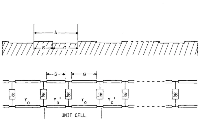
An equivalent transmission-line model was proposed by Li et al. for including second-order effects in the analysis of SAW gratings. [26,27] In this model, the energy storage is ac-counted for by a periodic loading of equal shunt susceptances across a transmission line [Fig. 1.2.1]. However, they proposed that the appropriate shunt susceptance value be determined ex-perimentally. This approach, while quantitatively predicting
the grating behavior, fails to relate the effects of energy
storage to the relevant grating parameters. In a later paper, an attempt was made by Shimizu et al. to derive the susceptance
A
s777777
s G
UNIT CELL
FIG.
1.2.1
EQUIVALENT
TRANSMISSION-LINE
MODEL FOR
elements of Li entirely theoretically. [30] However, because of a perturbation technique employed in their solution, the results are in error for steep-sided grooves.
In two recent papers, by Wright et al., a new method for
analyzing second-order effects in closed form was described.[31,32] That analysis will be given in detail in this thesis. The
re-sults are in good agreement with experimental data and reveal the critical importance of groove profile in determining second-order effects.
The analysis of second-order effects, and the other grating analyses considered in this thesis, are based on coupled-wave theory. Coupled-wave theory was first introduced into grating analysis by Kogelnik, for the analysis of thick hologram
gra-[33]
tings. Later Kogelnik and Shank successfully applied it to the analysis of distributed-feedback lasers. [341 They demonstrated that such an approach could greatly simplify the analysis of grating structures. Subsequently, coupled-wave theory was successfully applied by several authors to the analysis of SAW transducers and gratings.[13 5-3 7 1
Modern SAW grating devices such as the RAC, rely on ob-lique-incidence grating structures for their operation. How-ever, the coupled-wave theory developed by Kogelnik applied only to one-dimensional structures. Thus only gratings at
normal incidence could be analyzed. Coupled-wave theory was extended to two dimensions by L. Solymar et al., for the
[38]
analysis of large-volume holograms. Solymar et al. solved the problem of uniform illumination of a large-volume hologram at Bragg incidence. They showed that the output waveforms from a holographic grating could be expressed in terms of Bessel functions. Bloch et al., by analogy, applied these
solutions to the analysis of oblique-incidence SAW gratings.[391 Since the solutions were only valid at Bragg, however, they
were not able to predict the frequency behavior of the gratings. In addition they could not analyze the transmission through a
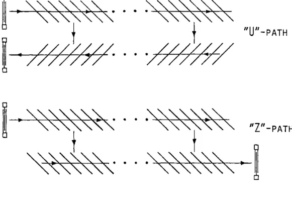
"U" or "Z" -path unchirped grating structure [Fig. 1.2.2]. In the latter structures the illumination of the second grating is non-uniform, thus the solutions of Solymar did not apply.
In a recent paper, Russell and Solymar extended the anal-ysis of large-volume overlap-holograms to the case of non-uniform illumination and non-Bragg incidence. However, these solu-tions have not yet been applied to the analysis of SAW grating structures. In addition, the solutions are valid only for gratings with a constant spatial-period. They thus cannot be
applied to the RAC, which is a chirped grating structure. Gerard et al. performed an analysis of the RAC in the
limit of small coupling between the incident and reflected
"UPATH
"z"_PATH
FIG.
1.2.2
"U"
AND
"Z"-PATH
GRATING
CON-FIGURATIONS.
RAC devices. However, under the small coupling assumption the effects of energy depletion and multiple reflections within the gratings are completely neglected. This analysis is there-fore unsuitable for the design of low-loss RAC devices, where the coupling in the gratings must be strong.
In a separate paper, Otto attempted to examine the effects
of multiple reflections on grating performance and also to
es-[42]
timate when they become important. He chose to analyze an unchirped U-path grating by dividing both gratings into small unit-cells, each with identical scattering parameters [Fig. 1.2.3]. By employing a computer to multiply together each of the individual scattering matrices, he was then able to invest-igate the role of multiple reflections on the performance of the device. The analysis, however, was only performed for unchirped gratings. Moreover, closed-form solutions were not obtained and the complexities of the numerical analysis failed to make clear the role of the design parameters in determining these effects.
In a recent paper, Bloch et al. suggested an extension of the unit-cell scattering approach of Otto to the analysis of a RAC (i.e. to include a chirped grating). [3 9 1 The method,
however, is not as well suited to this structure. In addition,
the complex numerical analysis required, again obscures a clear understanding of how these effects might be included for improved
INCIDENT
POWER
7>
S 0 5 S 0 *LJJiIT
aeoCE LL
UN IT
REFLECTED
POWER
(A)
SUBDIVISION OF GRATING INTO UNIT CELLS
b
a
a'
b'
(B)
UNIT CELL 4-PORT
REPRESENTATI
ON
bb
12
b1n
a1
2a
13aIa
a
a
a
21a
22a2n
2n2
0 0am
m3**aa
aml1ar
mn
am(n+l)
b
b(m+1)2
b
(C)
UNIT CELL MATRIX ANALYSIS OF GRATING
FIG.
1.2.3
UNIT-CELL APPROACH
RAC design.
More recently, a closed-form analysis of reflective-array gratings was reported by Wright et al. That analysis will be described in detail in this thesis. The new analysis, for
the first time, permits closed-form solutions to be obtained for the RAC. The solutions incorporate all orders of multiple reflections and wave depletion within the gratings. They have important application to the design of low-loss RAC's.
1.3. Objectives
A main objective of this thesis will be to demonstrate that, in many cases, coupled-wave theory provides the most
convenient approach to the solution of complex grating problems. In particular, we shall show that a coupled-wave analysis fre-quently permits solutions to be obtained in closed form. Al-ternate methods, by contrast, are invariably more complicated, frequently involve infinite matrices, and rarely permit closed-form solutions to be obtained. Furthermore, grating analyses of general validity can be performed, using coupling-of-modes theory, without regard to the specific nature of the waves, i.e. acoustic, optical, etc. We shall show that a coupled-wave analysis is valid for most grating structures of practical im-portance.
A new, relatively straightforward method for obtaining second-order effects in grooved gratings will be presented. The analysis will be performed assuming propagation in an
isotropic material. However, by invoking an equivalent
Poisson ratio, the results of the analysis will be extended to include typical anisotropic materials, such as Quartz and LiNbO3 The solutions will be obtained in closed form. Ana-lyses that involve numerical integration, and/or truncation
of infinite matrices, are particularly to be avoided as they may lead to incorrect results as will be shown.
All the stop-bands of a grating will be determined correct to second order in the groove depth. From this analysis the response of a grating at Bragg and the second harmonic will be examined in detail. Both normal- and oblique-incidence gratings will be considered. The second-order reduction in
the free-surface wave velocity within a grating, usually at-tributed to so-called stored-energy effects, will be determined theoretically and in closed form. The sensitivity of the re-sulting downward shift in the frequency of maximum reflection of the grating (i.e. Bragg) to the groove profile will be in-vestigated. It has been reported in the literature that this
frequency shift is not a simple quadratic function of groove depth, as might be expected. [25] We shall show that the new theory explains this behavior. We shall also determine the transmission phase response of a grating, using the corrected wave velocity as determined by the analysis. Whenever possible,
all theoretical analyses will be compared with existing
experi-mental data.
From the second-order analysis,the reflection coefficient of a grating will also be determined to second order (in groove
depth). Stored-energy effects have been shown to cause a strong grating reflection near the second-harmonic frequency, where
to first order none would be expected. This reflection, and the associated bulk radiation within the grating, will be
determined theoretically by the new analysis. The sensitivity of the reflection coefficient to the groove/strip ratio of the grating will be examined. We shall show that a second-order analysis reveals that a groove/strip ratio of 1:1 may not always be the ideal choice.
As a further example of the usefulness of coupling-of-modes theory in grating analysis, we shall derive exact, closed-form solutions for gratings with a linear spatial chirp. Both
normal- and oblique-incidence (450) gratings will be considered. All the grating waves will be obtained in closed form, and the
response at arbitrary detuning, to an arbitrary input profile, will be determined. Constant-period, or unchirped gratings, will be considered as limiting cases. The design of
constant-period oblique-incidence gratings as bandpass and bandstop filters will be described.
U-path grating devices will also be studied. In particular, a detailed analysis of the RAC will be performed. The emphasis will be directed towards understanding the effects of multiple reflections, within each grating, on the overall amplitude and phase response of the device. The implications of the new analysis for low-loss RAC design will be examined in detail, and distortions of the device response, caused by the previously
PART I
Analysis of Constant-Period SAW Grooved Gratings to First and
FIRST-ORDER REFLECTION COEFFICIENT FROM A VARIATIONAL PRINCIPLE
2.1. Variational Principle for SAW's
Variational principles are extremely useful in that they yield the values of parameters to an accuracy greater than that of the solutions used in deriving them. If a system undergoes a small perturbation, such principles permit the new perturbed solutions of the system to be determined from the unperturbed solutions. They are thus frequently used in resonator problems to determine the change in resonant frequency of the system, resulting from a small perturbing influence.
In this section a variational principle for SAW's is
developed. The analysis ignores the effects of piezo-electri-city and assumes propagation in an isotropic material. In the following sections, the variational principle is used to derive the coupled-wave equations for a normal-incidence grooved gra-ting. From these equations the reflection coefficient of a single groove is determined, in a simple manner, from the free-surface wave solutions.
Consider a SAW of angular frequency o, propagating on an isotropic acoustic material of mass density p. From
V
-* = p ;t2 u= - pw2uwhich in Einstein summation notation becomes
a.. = - P2(2.1.1) 3x.'
Multiplying by u,* gives I
3
-pW2 u.j2 = U.* 3 a.. (2.1.2)
Here a is the associated stress tensor of the wave and u is the displacement tensor. We now integrate (2.1.2) over the volume of one cell of the structure. The latter extends from the surface to z = +m (z into the bulk) and if the surface is periodic occupies one full period of the structure. We
ob-tain
pw2
f
dvju.j2 =f ds.u.*c.1. -fdv
[
u.* a..since the integration is over one full period and the surface is stress free (i.e. has no normal stress). Thus
fdv
[2u*1
aj
,f fdvu.I 2
or, introducing the stiffness tensor c
dv 9X .* c.. uk
-2 .3xk
dc(2.1.3)
p dvju i
2
This is the desired variational principle for SAW's. In this form, the value determined for W2 is stationary, when the correct solutions for the resonator are used to evaluate the expression. Any error in a trial function used to evaluate
(2.1.3), thus introduces only a second-order error in o. The variational nature of (2.1.3) is easily established.
Let LU be the exact resonant frequency of a SAW grating resonator. Let the stress and displacement of the exact solu-tions in the resonator bea0 . and u . respectively. Then
o
33-a0 9 0u(2.1.4)
ijkzax k
from (2.1.1) 0.= p2 . (2.1.5) Dx. C and, from (2.1.3) C) 0 2- f d v - -- u c .9 L X k u 9
o
2~
kv~Lu]Cjz
1
'
(2.1.6)
p4dviu.i2
Assume a trial solution for the resonator in the form u. =
u.0 + 6u.. The trial solution does not satisfy the
stress-1 1
free boundary condition on the surface of the resonator, i.e.,
C. - z' = 0, where z' is the surface-normal unit-vector. Using the trial solution to evaluate w2 from (2.1.3), we
shall ignore all terms of second, or higher, order in the error
term 6u.. Thus
dv (u7* + u. *)C. (u0 + Suz)
2 -- k
p dv(u.r + 6u.)(u?* + 6u.*)
1 1 1 1
= dv --- u.c.D. u 7+ (6u.*) c. .u
Lx
1i k 9x i ijkZ 9+ u(u )
Vp
{6dv[
ju. 2 + u 6u.*Ux ijkz 9 Xi i
0*
+ u. 3u. .
i
In any medium, cijk =C kji* [44] .. Hence, using the binomial
theorem, and relations (2.1.4) and (2.1.6)
W2 = 02
r~V9
0
*7
P
2
ro0*
ci..
(3 -+-(6u.) -pW
fdv[u.6u+
u.6u]
p v io 12 i i
fdv u*
JI
1013 CT . . + Su.9
Cy.+ 12i p02dv[u. 6u.+ u. 6u.i
- 2.. -
3
--00
p jdv ui 2
since the stress ci., of the exact solution in the grating,
ij-satisfies the stress-free boundary condition on the surface of the grating. Introducing (2.1.5) we obtain
H ,2 sin2
0
is of a higher order than that of the trial solution used to evaluate it.
2.2. Derivation of Coupled-Wave Equations
The coupling-of-modes formalism provides an elegant mathematical approach for determining the behavior of two coupled waves. For such a description to apply the local coupling (either in time or in space),, between the two waves, must be everywhere very weak. However, the resulting
inter-action between the two waves may be very strong, and in fact
complete power transfer may occur. We shall be concerned here with coupling-of-modes in space.
The advantage of a coupling-of-modes description lies in its generality. The form of the equations is unaffected by
the nature of the waves. It does not matter whether the two
interacting waves are both electromagnetic, acoustic, or a combination of the two. In addition, the details of the
structure and the coupling mechanism are avoided. The struc-ture is simply described by a coupling coefficient K between the two waves. The details of a particular structure, the type of waves involved, and the manner in which they interact, need only be considered when determining K. It is thus
advan-tageous, where possible, in a system containing two weakly
coupled waves to cast the governing equations in the form of coupling-of-modes. Once this has been done, much can be im-mediately ascertained about the behavior of the structure
by drawing on the large body of existing knowledge of coupled-wave equations.
We begin by presenting the coupled-wave equations of a distributed-feedback structure. We then show that the varia-tional principle (2.1.3) leads directly to this formalism for the wave amplitudes in a SAW grooved grating. The variational principle also determines the coupling coefficient K in terms of the physical parameters of the grating.
In a distributed-feedback structure (Fig. 2.2.1), the forward wave R(x) is coupled to a backward wave S(x) via a small periodic perturbation of the medium, along the propaga-tion direcpropaga-tion x. In the absence of coupling the waves have dependence
R(x)nu e (wtkX)
S(x) ej (Wk+kx)
where k = w/v is the propagation constant. The waves are strongly coupled when the period of the perturbation A = X/2, where X = 27/k is the wavelength of the propagating waves.
The wave scattered from R(x), by the k-vector of the pertur-bation k = -(2/A)x = -2kx, then has the propagation constant
p
(k + k ) = -k and is thus synchronous with S (x). The frequency at which this synchronous scattering occurs, and the coupling
R (x)
tAtx-
+--S(x)PERIODIC PERTURBATION
OF MEDIUM
FIG.
2.2.1
DiSTRIBUTED-FEEDBACK
STRUCTURE
R
Sr x
FIG.
2.2.2
SURFACE-WAVE GRATING
between the two counter-propagating is a maximum, is referred to as Bragg.
Before writing the coupled-wave equations, we introduce the slowly varying wave amplitudes M(x) and S5(x), where
(wt-kx)
R(x) = R(x) e
S(x) = (x) e(t+kx)
The coupled-wave equations for the Bragg condition, are then 14 51
d (x) = K 3(x)
dx
(2.2.1) d S(x) = K* R(x).
dx
We now use the variational formula (2.1.3) to determine the governing equations for the waves in a SAW grooved grating. We shall show that these equations can be cast in the same
form as (2.2.1) and identify the coupling coefficient K. For an acoustic substrate, extending from z = 0 to z = +co, the solutions for guided waves propagating along the surface in the x - y plane are well known Rayleigh waves.
is the Rayleigh wavelength. These waves no longer satisfy the stress-free boundary conditions if the surface is perturbed by a grating. However, the Rayleigh wave solutions will be used as zeroth-order trial solutions in the variational principle
(2.1.3).
Consider an acoustic substrate with a surface grating of infinite extent in the x direction, and of period A (Fig. 2.2.2). The perturbed boundary is at z = A f(x), where
r
E(= h/X '<1, and the normalized surface perturbation f(x)
r
has a peak amplitude of unity. We seek to determine the per-turbed wave solutions for forward and reverse guided SAW's along the x direction, and the degree of coupling introduced between them by the grating. Ignoring diffraction, no depen-dence on y will be assumed. If the grating were not present
(i.e. c = 0) the forward and reverse wave solutions would both be Rayleigh waves. Thus,we take as a trial solution for
the variational principle (2.1.3)
u. Ru. + +Su. (2.2.2)
where u. are the displacements of the (zeroth order) Rayleigh wave solutions. The wave amplitudes R and S are assumed to be slowly varying functions of x, such that
A(dR/dx) << 1 and A(dS/dx)< 1.
R S
Introducing the trial solution (2.2.2), into the variational principle (2.1.3), thus gives
dvfR*
u2
+ S* u. C.. R u + S Uf3x 13x 3k xk3xk
+* -* +
-P dv(R*ut S*u. )(Ru. + Su.) 2-1 1
(2.2.3)
where the integration in x is taken over one full period A. We now determine the relationships between R and S, necessary for w to be a minimum. Since the trial solution is correct to zeroth order, the variational principle will yield relationships that are correct to first order (in c). In the analysis all terms of the order E2 (O(E2)) and above will thus be neglected. To derive the requirements for w2 to be
sta-tionary we differentiate (2.2.3) with respect to the wave
am-plitudes R and S. This may be shown to be equivalent to differentiating with respect to R* and S*. The results are
W2 P vRu+12 {p
f
+S+* - v R+ 1 * C. +R1Ij+*
WJ
URu
K+
Su ui]}=TdvLR
Lut
ijk -u-'
s U. c..u
Uk' U
+S
3u
Xk-w2{pfdv[Si+u>2 ++Ru -u} dv s u -c ku
+
JLVl~
i ijkz + R-u. c.. u.9x.
' cijk2. 9xk Defining + * -dv u. u. 1 H +=f
dv u. U. +v c.i, *9
uz aC. 9X 1 ikz z ] Skthe equations become
w
2 K R + W2K+-S = H+R + H+ S wO2K S + w2K R = H S + H R. (2.2.4) Evaluating H++, we have 9 +* +F+*
+ = dv u- u. c -. u =fds. u. ci . - u 1 ijZ x Z =1x 9x k kdvc..-I--u+1 =- dv u* *..
i 9x 13k2, x z 9 3 13
9x
Xk
Sx
where the surface integral vanishes because the integration is over one full period of the grating. Denoting the angular
fre-quency of the unperturbed Rayleigh waves by w0 , and introducing (2.1.1), we obtain H+ = pw ++ o1"Jo 2
jdv
++ut ui = w02 K . Similarly, H 2 K -0
--Evaluating H+- we have;+*
jk
-H = dv u. c.. ku9 +- 3 DXk k = ds. u. c..u 3 ijk 3 U9z 9xk -Jdvu.- c. u3
k
k
k
Dx Dk x k ={
ds. u. T .. -{dv
u7 c.. 13x.3
Defining0
+*-C.=
dS.u. U..and again introducing (2.1.1), we obtain
H +*
HW =0 p dv u. u. =C + 2
Similarly,
H C + W 2K
-+ -+ 0 -+
Substituting in (2.2.4) the relations between R and S be-come (W2 - Wo2)KHR + (2 - W02)K S = C S 0(+. +- +
(2.2.5)
(W2 -W 2)K S + (2 - W2)K R= C R. -0- -+ -+The waves within the grating have propagation constants of kr .r but are of frequency w. The presence of the grating thus perturbs the frequency of the waves from the free surface Rayleigh wave frequency w0. We may Taylor expand w in terms of the perturbation parameter e
WU = W 0 + WE +
Introducing this expansion into (2.2.5), to O(E), we obtain
2Eww K S = CR 2 E W0 -- S - +R or cw1R = S 12 0K++I (2.2.6) Eol =
[R.
2w KThe second terms on the LHS of (2.2.5) do not contribute to these equations, since K+- and K-+ are themselves of O(e).
The grating waves have time dependence eJot. For the
slowly varying wave amplitudes R and S we therefore identify the time derivative, 9/9t = jew. Thus equations (2.2.6) take the form
R =
j
S
=j.R.
at 2woK
By reciprocity Ju.
I=Iu,+I,
and C_=+C* DefiningKt =
j
(2.2.7) 2w K+1 we have -L = Kt S at (2.2.8) S = -K*R t twhich are of the general form of coupling-of-modes in time. These equations describe the time evolution of the wave ampli-tudes in the grating. However, we are interested in the spatial evolution of the waves. The corresponding coupling-of-modes equations in space are easily obtained.
A plane wave, of unspecified nature, propagating in the
j
(wt-kx)
+x direction has the general dependence e . The pro-pagation constant k is given by k = o/v, where v is the velocity of the wave. Thus
9t
= -jk =
-jw/v.
Dx
Hence, for a wave propagating in the +x direction
9
193
9x
v 9t
Similarly, for a wave propagating in the
-x direction
9 _19
9x
v Dt
From (2.2.8) the coupling-of-modes equations in space are
therefore,
R = KSax
(2.2.9) S = K*R9x
where from (2.2.7), the spatial coupling coefficient is given by
K = -K
I
= -JIn (2.2.10) vr waves.
ds. u, c..
2v ru)o p dv l u + 2
is the velocity of the zeroth-order Rayleigh
The homogeneous equations (2.2.9), obtained for R and S using the variational principle, are thus identical in form to the resonant coupling-of-modes equations (2.2.1) for a dis-tributed-feedback structure. The specific form of the coupling coefficient K, for a surface-wave grating, has been determined, by the variational analysis, in (2.2.10).
2.3. First-Order Reflection Coefficient
We now evalute the coupling coefficient K, determined in Section 2.2, in terms of the grating parameters and the
Rayleigh wave constants. From this evaluation the first-order
reflection coefficient of a Rayleigh wave from a single normal-incidence groove is obtained.
The coupling coefficient K, between the forward and reverse waves in a SAW grating, is given by (2.2.10). We
con-sider a grating of period A, where the grating boundary is defined by z = EX f (x) [Fig. 2.2.2]. The surface
perturba-r
tion f (x) has a peak amplitude of unity. In Appendix A the stress on the surface of a grating a5, due to an acoustic
wave, is determined. For a Rayleigh wave,from (A.5), we have
to O(E)
- r =Xar' -ar + ACr
a = Exr[f(x) (0) - f'(x) a (0)]x + E f(x) (0)z
s
r
xz
xx
r
zz
where ar (0) = a..1J
IJz=0
andri
r
a'?. (0) = a. 9z z=0Hence, to O(sE) +* _A r*-r' -r ds . u.I . . = [Ardx {u (0)[f(x) a (0) - f'(x) r (0)] 3 Jr x xz xx + U f (x) (0)1 (2.3.1)
z
zz
where the superscript (-r) denotes a backward Rayleigh wave (propagating in the direction -x), and
ur = urr0)
x x
In Appendix B the displacements, stress components, and the dispersion relation for Rayleigh waves are derived. Again, let the amplitude of the forward wave be denoted by R, and
that of the backward wave by S. Evaluating (2 .3.1), using the
displacements and stress components given in (B.20), and using the Rayleigh wave dispersion relation (B.18) gives
ds. ds i . rij .. = 2ps\ R*S k.2(r q q
odx
f(x) e2Jkrx r 2 r r) r(2.3.2)
-2jk
xwith dependence e r contributes to the integration. The latter result was made use of in obtaining (2.3.2), by identi-fying f'(x) = -2jkrf(x).
Considering the denominator of (2.2.10), we have
2vrw p
{dvjuj
2 = 2vroPA dzIuiI2.(2.3.3)
However, the time average power (per unit width) of a forward propagating Rayleigh wave is
P = v W r r
where W is the time average energy of the wave per unit sur-face area of the solid. Thus,
W p 2
{f
dz utrI2. 2 0 Hence, vrr2dz
IuirK2. (2.3.4) But from (C.3) r = 2rpk 2 o;I (2.3.5)where Y is a dimensionless quantity, analogous to a
charac-0
teristic admittance for the solid. From (C.5)
=k (kr2r - kr2%+2q 2r)
(2.3 Y 0= k r 3r r r(2.3.6)
o
2
32k
3q
3r
r r r
A plot of Y0, as a function of the isotropic Poisson ratio v = X/2(X + j), is given in Fig. 2.3.1. Substituting in
(2.3.3) from (2.3.4) and (2.3.5), we obtain
2vr
Jo
dvjui+2= 8pk22
RA
YJJ. (2.3.7)
The magnitude of the coupling coefficient K, in a SAW grating, is now readily determined. By reciprocity RI =
IS.
Introducing (2.3.2) and (2.3.7) into (2.2.10), and noting that for an isotropic material
k2 > k
and thus
r r >q r
1.0 -- Y0 [P = 2wpk22 y 0 R 22]
0
8
ST QUARTZ
(-v = .41)0.6--
Y-Z
LiNb0
3(v
=.335)
0.4
0.2
0.1
0.2
0.3
04
0.5
POISSON RATIO
(v)
ADMITTANCE
VS.
POISSON
RATIO
(rr - qr )q r A 2jk rx K = (r r r 1Adx f(x) e r .r
4AY-0
If the normalized surface perturbation f(x) into a Fourier series
is decomposed 0o f(x) =
A
cos(n k x) n=l g then at Braggk
= 2k g r and, at p x Bragg,k
= 2k/p.
g rHence,
AA, 2jk x 2 dx f(x) et
A , 2AP at Bragg at p-th harmonic.From (2.3.8) the magnitude of the first-order coupling coeffi-cient in a normal-incidence SAW grating is thus, at Bragg
(2.3.8)
A
(r - q )g
Kj=EA r r rA
8Y
0
and in general, at the p-th harmonic
(rr -
q
r r KI= EA rrA . r Byp (2.3.9) (2.3.10)Finally, we determine the first-order Rayleigh wave re-flection coefficient of a single normal-incidence (two-sided) groove. To be consistent with previous work we define the re-flection coefficient to be 2r. 4 6 Since 2r = KIKA, we have
S
(A
r/
2),
2r={r(A/2)p,
at Bragg
at p-th harmonic
Thus from (2.3.9)-(2.3.11), and replacing A = (2Tr/k
),
atr r Bragg
2r-E
Tr2(rr - r 4k 2 y r o (2.3.12)and in general, at the p-th harmonic
CIr 2(r. qg
2r-
=
rpA
-4k 2 y P r o (2.3.13)
(2.3.11)
For the special case of an "idealized" grating, with a square-wave profile, A = 2/n7 for n odd, A = 0 for n
n
n
even. Thus, at Bragg and the odd harmonics,
cr(r - q )q
2r= r r r 2.3.14)
square 2kr Y
wave 0
and, at the even harmonics,
2r =0
square wave
to O(s). The reflection coefficient of an idealized grating at the odd harmonics (2.3.14) is plotted in Fig. 2.3.2, as a function of the isotropic Poisson ratio V. Throughout this thesis to apply the results of the analyses to typical aniso-tropic substrate materials, we shall use the concept of an
[47]
"equivalent isotropic Poisson ratio". In particular, we shall use the theoretically derived values of v = .335 for Y - Z LiNbO3, and v = .41 for ST Quartz.[3 01
Thus, from Fig.
33
2.3.2 we find that for Y - Z LiNbO3 2ru0z.69E5, and for
(2n+1) (Xr/4) 2r h = Er
1.2
-1.0
0.8--
Y-Z LiNb03 (V = .335)ST QUARTZ
0.6--N .41)0.4
0.2
o.10,2
0.3
0.4
0.5
POISSON RATIO
(v)
FIG.
2.3.2
NORMALIZED FIRST-ORDER GROOVE REFLECTION
COEFFICIENT (AT ODD HARMONICS) VS.
POISSON
RATIO.
CHAPTER 3
FIRST-ORDER REFLECTION COEFFICIENT FROM BOUNDARY CONDITIONS
3.1. Coupling-of-Modes Approach
In Chapter 2 the first-order reflection coefficient of
a normal-incidence groove was obtained from a variational
principle. An alternative approach is now presented.
The method to be described is based on determining the width of the grating stop-band, by considering the boundary
conditions on the surface of the grating. By means of
coupling-of-modes theory the reflection coefficient of a single groove of the grating is then determined. The approach is "quasi-variational", in that the reflection coefficient, and the width of the stop-band, are obtained to one higher order (in c)
than the stresses used in the analysis.
The coupled-wave equations for a normal-incidence grating
are
9-2jx
R(x) = K ejxS(x)9x
(3.1.1)
_ 2j S(x) = K* ej R(x)9x
of the two counter-propagating waves, i.e.
j(wt-k
rx)R
(x)
=j(wt-kx)
j(Wt+krx)
s (X) =s(X) e(3
.1. 2)
The parameter A is the amount by which the waves are "detuned" from the synchronous frequency of the grating to.
A-
0 (3.1.3)r
where (o0/vr)A =
prr
(p =1
at Bragg). The dispersion rela-tion for the forward wave R(x), is easily obtained. From(3.1.1)-R(x) + 2jA -- R(x) - K12 R(x) = 0.
9x
2g
Assuming a solution of the form eJQX gives
a2 - 2ac + K1 2 = 0
a =
A
2If the propagation constant of R(x) is denoted by
s,
then from (3.1.2)-(3.1.4)= k + a = (w /v
)
A2- K1 2. (3.1.5)
r
a
r
This dispersion relation is shown schematically in Fig. 3.1.1. We observe that within the grating stop-band the propagation
constant
1
is complex. The stop-band is symmetric aboutw0 and is of width(W+ - W-)
=
2 K!.
(3.1.6)v
r
At the upper and lower stop-band frequencies, w+ and w_ respectively, the propagation constant is equal to that of a free-surface Rayleigh wave of frequency Wo, i.e.
() = kr =w0/r = p7/A. (3.1.7)
In the above analysis
1
was determined for a given o. However, we may instead choose to define 1 and determine theresulting w. This will be the approach used in determining the grating reflection coefficient from boundary conditions.
I
K-2IKJ
I
N
%oftcowIMAGINARY $
- 0
W
+ toFIG,
3,11
FIRST-ORDER GRATING DISPERSION
DIAGRAM,
S
VS.
o,k
r
-A
Interchanging the dependent and independent variables 3 and W in Fig. 3.1.1, the dispersion diagram is redrawn in Fig.
3.1.2. The procedure to be followed for determining the re-flection coefficient will now be described.
The method is based on determining the upper and lower frequencies of the stop-band, w+ and w_ respectively. At these frequencies the fundamental waves, propagating in the
Tk x
grating, have dependence e r , with kr given by (3.1.7).
From (3.1.7)
2kr,
at Bragg
k = 27w/fA = (3.1.8)
2kr/p, at p x Bragg
Assuming propagating wave solutions in the grating, with
de-~jk
xpendence e r , the frequency of the waves is determined
from the grating boundary conditions. Requiring the surface of the grating to be stress free leads to two determinantal
equations that determine w+ and _ . The coupling coefficient of the grating is then obtained from (3.1.6) and the reflection coefficient of a single groove computed from (2.3.11).
A significant advantage of this method is that in deter-mining the perturbed frequencies (W+ and w_) to O(E),
ojk x
Aw/
\
No
k
r
FREE
SURFACE
IMAGINARY
6
/
L oW0 +W -PrA
FIG.
3,1.2
FIRST-ORDER GRATING DISPERSION
DIAGRAM,
LVS,
$,W()
w0
I EM
need be considered. Though components with other spatial
dependencies are of finite amplitude to O(E), in the grating, they are not required in the analysis. The method is thus computationally very efficient with similar advantages to the variational principle of Chapter 2.
3.2. Determinantal Equations from Boundary Conditions
In this section the first-order determinantal equations are derived, from which the upper and lower stop-band frequen-ciesw+ and o respectively (Fig. 3.1.2), are to be
de-termined.
At w+, o the fundamental waves in the grating have
wjk
xdependence e , with k given by (3.1.7). To satisfy
r
the boundary conditions on the surface of the grating to O(E),
we shall assume these waves to comprise a compressional wave
and a vertical shear wave propagating in the direction +x; also a compressional wave and a vertical shear wave propagating in the direction -x. The amplitudes of these waves are zeroth order (and above) in 6, the depth of the grating perturbation, since these solutions continue to exist for E = 0. In the
limit C = 0, each pair of co-propagating waves combines to form a Rayleigh wave. However, for E
A
0 the ratio of the shear/compressional wave amplitudes of each pair is differentfrom that of a Rayleigh wave, by O(s). In addition,the waves
no longer satisfy the Rayleigh wave dispersion relation (B.18). To satisfy the boundary conditions on the surface of the
grating completely, to O(E), additional wave components with
other spatial dependencies are required. These waves, however, exist only in the presence of the grating (E
A
0) and are thusof O(E) (or above). As discussed in Section 3.1, the ampli-tudes of these waves are not required to determine the deter-minantal equations for the upper and lower stop-band frequencies to O(E). (We shall see later in this thesis that these waves are responsible for the stored-energy effects in the grating.)
From (A.4) the stress on the surface of the grating is,
to O(C) a = {a (0) + s [ xf(x)za' (0) - f'(x) a (0)]} x
s xz
r
xz
xx
+ {a (0) + EXr [f(x) 'z(0) - f'(x) a (0)]} z (3.2.1) where a. (0) = a.1J
i
z=0
anda!
. (0) = ii z 3 z=0As in section 2.3 we represent the normalized surface
pertur-bation f (x) by a Fourier series
CO
f(x) = IAn cos(nk x) (3.2.2)
thus
CO
f'(x) = - nk A sin(nk x). (3.2.3)
n=l g n g
Since the surface of the grating is a free boundary, it must be stress free i.e. a = 0. This condition, from
(3.2.1)-(3.2.3), requires
J (0) + Ex A cos(nkgx) a' (0) +
I
1
nkgA sin(nkgx)xz r Ln= 1 n g9 x n=1
a (0) }=0 (3.2.4)
* (0) + EAr An cos(nkgx) a' (0) + nk A sin(nkgx)]
z Z r _n= ngn= g ng
aYxz (0) = 0. (3.2.5)
The only waves in the grating with a finite zeroth-order ampli-wjk x
tude (in E) are the propagating waves with dependence e
Thus, to O(C) only the stress components of these waves are required in the terms CAr{ } of (3.2.4) and (3.2.5). The latter terms thus comprise, in general, an infinite set of
;jk x
Wi)nk x
components with the dependence e r e 9. From (3.2.4) and (3.2.5) the same wave components are required for ax (0)0, a z(0). Thus, an infinite set of waves with spatial dependence
jk x (T-)jnk x..
e rX eg is required to satisfy the boundary conditions on the surface of the grating to O(E). The wave components with n ; 0 are referred to as Brillouin components and are of O(s) (or above).
Equations (3.2.4) and (3.2.5) must be satisfied separately for each of the spatial dependencies of the waves. The deter-minantal equations, for the upper and lower stop-band frequen-cies, are obtained by considering only those terms with the spatial dependence of the fundamental waves, e
jkrX.
To simplify the analysis the following notation is intro-duced. The amplitude of the acoustic waves with spatial depen-dence e+JkrX is denoted by Si, where
for compressional wave
2, for shear wave.
Also the x-independent stress components of these waves a'+ are defined by
_ + +