HAL Id: tel-01905820
https://tel.archives-ouvertes.fr/tel-01905820
Submitted on 26 Oct 2018HAL is a multi-disciplinary open access
archive for the deposit and dissemination of sci-entific research documents, whether they are pub-lished or not. The documents may come from teaching and research institutions in France or abroad, or from public or private research centers.
L’archive ouverte pluridisciplinaire HAL, est destinée au dépôt et à la diffusion de documents scientifiques de niveau recherche, publiés ou non, émanant des établissements d’enseignement et de recherche français ou étrangers, des laboratoires publics ou privés.
Synthesis, characterization and industrial applicability of
combined sorbent-catalyst materials for sorption
enhanced steam methane reforming
Andrea Di Giuliano
To cite this version:
Andrea Di Giuliano. Synthesis, characterization and industrial applicability of combined sorbent-catalyst materials for sorption enhanced steam methane reforming. Catalysis. Université de Stras-bourg; Università degli studi (L’Aquila, Italie), 2017. English. �NNT : 2017STRAF065�. �tel-01905820�
UNIVERSITÉ DE STRASBOURG
UNIVERSITÀ DEGLI STUDI DELL’AQUILA
École Doctorale des Sciences Chimiques, ICPEES UMR CNRS 7515 - ECED
Dipartimento di Ingegneria Industriale e dell’Informazione e di Economia
THÈSE en cotutelle
présentée par :Andrea DI GIULIANO
soutenue le : 19 décembre 2017
pour obtenir le grade de :
Docteur de l’Université de Strasbourg
Discipline / Spécialité :Chimie / Catalyse hétérogène
pour obtenir le grade de :
Dottore di Ricerca dell’Universià degli Studi dell’Aquila
Discipline / SSD : Ingegneria industriale e dell’Informazione e di Economia / ING-IND/24, ING-IND/27Synthesis, characterization and
industrial applicability of Combined
Sorbent-Catalyst Materials for Sorption
Enhanced Steam Methane Reforming
THÈSE dirigée par :
Mme Claire COURSON Maître de conférences, Université de Strasbourg
M Pier Ugo FOSCOLO Professeur, Università degli Studi dell’Aquila
RAPPORTEURS :
Mme Catherine BATHIOT-DUPEYRAT Professeur, Université de Poitiers
M Gianpiero GROPPI Professeur, Politecnico di Milano
MEMBRES DU JURY :
Mme Nathalie TANCHOUX Chargé de recherches, Université de Montpellier
Mme Mirella VIRGINIE Maître de conférences, Université de Lille 1
Mme Maria Cristina ANNESINI Professeur, Università degli Studi di Roma La Sapienza
Do what I do:
hold tight and pretend it’s a plan!
Matt Smith, as the 11th Doctor BBC Doctor Who
It … could … WORK!!!
Gene Wilder, as Doctor F. Frankenstein
Young Frankenstein
Where is the wisdom we have lost in knowledge?
Where is the knowledge we have lost in information?
T. S. Eliot
Abstract
Sorption enhanced steam methane reforming (SESMR), i.e. steam methane reforming (SMR) with in situ CO2 sorption by a high temperature solid sorbent, can lead to a
sustainable and economical exploitation of natural gas to produce high purity H2 for power
generation and production of chemicals, with simultaneous sequestration of greenhouse gases. The European research project ASCENT (Advanced Solid Cycles with Efficient Novel Technologies), active from March 2014 for four years, among several goals, aims to give a solid proof-of-concept of SESMR industrial applicability by a Combined Sorbent Catalyst Material (CSCM).
This thesis, as part of ASCENT project, deals with Ni-mayenite SMR catalysts, CaO-mayenite CO2 sorbents, and Ni-CaO-mayenite CSCM for SESMR. These materials
were successfully synthesized by wet mixing and wet impregnation methods, to study the effect of Ni fraction, its precursor salt (Ni-nitrate or Ni-acetate), and free CaO fraction. ICP-AES, XRD, BET and BJH methods, SEM-EDS, TEM-EDS, TPR and TGA were largely used as characterization techniques. The reactivity of synthesized material was evaluated by tests in a packed-bed microreactor, which served also as a screening tool to choose the most promising materials. Their industrial applicability was further assessed by multicycle SESMR/regeneration tests in an automated packed-bed bench scale rig.
Microreactor scale tests indicated that: (i) Ni-acetate shows lower reactivity towards reforming than Ni-nitrate, with both Ni-mayenite catalysts and Ni-CaO-mayenite CSCM; (ii) CaO presence causes a depletion of Ni reactivity in CSCM, and even in raw mixing of Ni-mayenite and CaO-mayenite; (iii) the detrimental effect of CaO can be faced by a sufficiently high Ni fraction.
Based on these evidences, a CSCM with high Ni fraction (10 wt%) from Ni-nitrate, deriving from a sorbent with low CaO excess (15 wt%) was chosen for multicycle tests. This material performed satisfactorily in 205 consecutive SESMR/regeneration cycles, with mild regeneration conditions (pure N2 at 850 °C), showing a very stable behaviour.
On the other hand, with more severe regeneration conditions (pure CO2 at 925 °C), the
same material suffered an important deactivation, attributed by post-test characterization to a textural decay and Ni rearrangement.
Il sorption enhanced steam methane reforming (SESMR), cioè lo steam methane reforming (SMR) con cattura in situ di CO2 per mezzo di un sorbente solido ad alta temperatura, è
considerato un processo interessante al fine di un utilizzo sostenibile ed economicamente conveniente del gas naturale per la produzione di H2 di elevata purezza, da usare per la
generazione di energia elettrica e/o di composti chimici, con un simultaneo sequestro di gas serra. Il progetto di ricerca europeo ASCENT (Advanced Solid Cycles with Efficient Novel Technologies), attivo da marzo 2014 per quattro anni, tra i suoi obiettivi, mira a fornire una concreta dimostrazione dell’applicabilità industriale del SESMR con materiali combinati sorbenti catalizzatori (CSCM).
Questa tesi è stata svolta nell’ambito del progetto di ricerca ASCENT: riguarda catalizzatori Ni-mayenite per SMR, sorbenti CaO-mayenite per la cattura di CO2 e CSCM
Ni-CaO-mayenite per il SESMR. Questi materiali sono stati sintetizzati con successo tramite i metodi wet mixing e wet impregnation, per studiare l’effetto della frazione di Ni, del sale precursore di Ni utilizzato (acetato di Ni o nitrato di Ni), della frazione di CaO libero. Le tecniche ICP-AES, XRD, metodi BET e BJH, SEM-EDS, TEM-EDS, TPR e TGA sono state largamente utilizzate per la caratterizzazione dei materiali sintetizzati. La loro reattività, invece, è stata valutata tramite test in micro-reattore a letto fisso, che sono anche serviti per una selezione dei materiali più promettenti per uno studio di applicabilità industriale con test multi-ciclici di SESMR/rigenerazione in un impianto a letto fisso da banco.
I test in micro-reattore hanno indicato che: (i) l’acetato di Ni conferisce alla Ni-mayenite e ai CSCM Ni-CaO-mayente una reattività inferiore verso il reforming rispetto al nitrato di Ni; (ii) la presenza di CaO causa una diminuzione della reattività del Ni nei CSCM, ma anche in miscele eterogenee di Ni-mayenite e CaO-mayenite; (iii) gli effetti negativi ascrivibili al CaO possono essere contrastati con una frazione di Ni sufficientemente alta.
In base a tali evidenze, è stato scelto per i test multi-ciclici un CSCM ad alta frazione di Ni (10 wt%) da nitrato, derivante da un sorbente a basso tenore di CaO libero in eccesso (15 wt%). Questo materiale ha garantito una prestazione soddisfacente e molto stabile per 205 cicli consecutivi di SESMR/rigenerazione, applicando condizioni di rigenerazione temperate (N2 puro a 850 °C). Con una rigenerazione più severa in CO2 pura a 925 °C,
invece, lo stesso materiale ha subito un’importante disattivazione, che tramite le caratterizzazioni post-test è stata attribuita al decadimento delle proprietà strutturali e al ri-arrangiamento del Ni.
***
Le procédé SESMR (Sorption Enhanced Steam Methane Reforming), c’est-à-dire le SMR (Steam Methane Reforming) avec capture de CO2 in-situ par un adsorbant solide à haute
température, peut amener à une exploitation durable et économique du gaz naturel pour la production de H2 à haute pureté pour générer de l’énergie électrique, en capturant le gaz à
effet de serre. Le projet de recherche européen ASCENT (Advanced Solid Cycles with Efficient Novel Technologies), actif depuis février 2014 pour une durée de 4 ans vise à fournir, entre autres, une démonstration concrète de l’applicabilité industrielle du SESMR par des matériaux combinés adsorbants-catalyseurs (CSCM).
La thèse, partie du projet de recherche ASCENT, concerne le développement d’un catalyseur Ni-mayenite pour le SMR, d’adsorbants CaO-mayenite pour la capture de la CO2, et de CSCM Ni-CaO-mayenite pour le SESMR. Ces matériaux ont été synthétisés
avec succès par mélange humide et par imprégnation par voie humide, aux fins d’étudier les influences dues à la fraction de Ni, aux sels précurseurs du Ni (Ni-acétate ou Ni-nitrate), et à la fraction de CaO disponible. Les techniques ICP-AES, XRD, BET/BJH, SEM/EDS, TEM/EDS, TPR et TGA ont été largement utilisés pour caractériser les matériaux synthétisés. Leur réactivité a été évaluée par des tests en lit fixe à l’échelle du microréacteur, qui ont aussi permis une sélection des matériaux les plus prometteurs pour une étude de l’applicabilité industrielle par tests multi cycliques SESMR/régénération de solides par un réacteur automatisé à lit fixe.
Les tests en microréacteur ont indiqué que : (i) le Ni-acétate donne aux catalyseurs Ni-mayenite et aux CSCM Ni-CaO-mayenite une réactivité envers le vaporeformage beaucoup plus basse que le Ni-nitrate ; (ii) la présence du CaO cause une diminution de la réactivité du Ni des CSCM, mais aussi en mélanges bruts de Ni-mayenite et CaO-mayenite ; (iii) les effets négatifs du CaO peuvent être combattus par une fraction de Ni suffisamment élevée.
En se basant sur ces évidences, on a choisi, pour les tests multi cycliques, un CSCM avec une grande fraction de Ni (10 wt%) issu du nitrate, et un adsorbant à faible teneur de CaO en excès (15 wt%). Ce matériau a garanti une performance satisfaisante et très stable pendant 205 cycles de SESMR/régénération du solide, sous des conditions de régénération modérées (sous N2 pur à 850 °C). Par une régénération plus dure sous CO2 pur à 925 °C,
au contraire, le même matériau a subi une importante désactivation, qui a été attribuée, par caractérisation après-test, à une dégradation texturale et à un réarrangement du Ni.
R sum de la th se
1
Introduction
La thèse s’intègre dans le cadre du projet de recherche ASCENT (Advanced Solid Cycles with Efficient Novel Technologies), financé par l’Union Européenne (numéro du projet 608512) et qui a débuté en mars 2014, impliquant 16 partenaires (universités européennes, instituts de recherche, petites et moyennes entreprises). ASCENT étudie différents procédés de production d’énergie décarbonée, basés sur l’utilisation d’un matériau solide absorbant de CO2 à haute température, permettant l’élimination simultanée de CO2 et la
conversion des autres gaz carbonés (c’est-à-dire CO ou CH4) en H2, en orientant les
recherches vers un futur développement commercial [1]. H2 est actuellement
principalement produit par SMR (Steam Methane Reforming) à l’échelle industrielle. Il existe différents matériaux capables de catalyser la réaction de SMR, néanmoins, des raisons économiques soutiennent le choix de catalyseurs au Ni supportés [2].
L’Université de L’Aquila participe aux recherches concernant le procédé SESMR (Sorption Enhanced Steam Methane Reforming) mis en œuvre par une boucle chimique au calcium, c’est à dire utilisant des absorbants à base de CaO pour la capture in situ de CO2.
Les réactions principales sont la réaction de SMR (Réaction 1) associée à la réaction de Water Gas Shift (WGS, Réaction 2) et la carbonatation de CaO (Réaction 3) [3] :
CH4(g) + H2O(v) ↔ CO(g) + 3H2(g) ΔH0298 K = 206.2 kJ mol-1 Réaction 1
CO(g) + H2O(v) ↔ CO2(g) + H2(g) ΔH0298 K = - 41.2 kJ mol-1 Réaction 2
CaO(s) + CO2(g) ↔ CaCO3(s) ΔH0298 K = - 175.7 kJ mol-1 Réaction 3
La Réaction 3 déplace l'équilibre du WGS (Réaction 2) vers la droite, en éliminant le CO2 gazeux, de sorte que la fraction gazeuse d’H2 augmente (d’où le nom « amélioration
par absorption »).
Les conditions opérationnelles appropriées pour effectuer les réactions 1 et 2 catalysées par le nickel (Ni), conjointement à la Réaction 3, sont de 650 °C et 1 ATM. Néanmoins,
CaO étant finalement saturé, le matériau absorbant doit être régénéré pour continuer le processus : la stratégie la plus commune consiste en une augmentation de la température vers 800-900 ° C, à 1 atm, afin d'inverser la Réaction 3 et de récupérer CaO [4]. Par conséquent, du point de vue du solide, le procédé SESMR peut fonctionner comme une alternance d’absorption de CO2 et de régénération de l’absorbant : le double lit circulant
fluidisé est une configuration appropriée, avec un réacteur opérant comme reformeur et l'autre comme régénérateur de l’absorbant [5].
En ce qui concerne la stabilité de la capacité d’absorption de CO2 pendant les
multicycles de carbonatation/calcination, les absorbants à base de CaO posent un problème, car la capacité de sorption de CaO diminue fortement avec l'augmentation du nombre de cycles [6]. Ceci est principalement dû au frottage de CaO, qui peut être limité en intégrant CaO dans un matériau inerte [7]. La mayenite (Ca12Al14O33) et d'autres aluminates de
calcium (par exemple, Ca9Al6O18 ou Ca3Al2O6) sont largement utilisés comme dispersant
dans des matériaux synthétiques [7]. La stabilité de l’activité catalytique au long de ce processus cyclique constitue un autre problème.
La faisabilité du procédé SESMR par des systèmes contenant un mélange brut de catalyseur et d’absorbant est prouvée dans la littérature [8]. Afin d'éviter une résistance mutuelle entre les réactions endothermiques et exothermiques, la notion de CSCM (Combined Sorbent Catalyst Materials), c'est-à-dire l’utilisation d’un seul matériau contenant, à la fois une phase absorbante de CO2 et une phase catalytique pour la réaction
de SMR, a été proposé [9]. En outre, l'utilisation de CSCM au lieu d'un système équivalent de mélange brut de catalyseur et d’absorbant réduit considérablement la quantité totale de solide dans le réacteur. Dans ce cadre, diverses synthèses de matériaux CSCM de type Ni-CaO-CaxAlyOz et leurs performances expérimentales sont rapportées dans la littérature
[10].
Finalement, la thèse rapporte une étude de catalyseurs Ni-mayenite de SMR, d’absorbants de CO2 CaO mayenite et de CSCM Ni CaO mayenite concernant leur :
• Synthèse par mélange humide (pour produire la mayenite ou CaO mayenite) et par imprégnation par voie humide (pour ajouter du Ni aux produits des mélanges humides, afin de produire, respectivement du mayenite ou du Ni-CaO-mayenite) [8] ;
• La caractérisation par les méthodes ICP-AES, XRD, BET et BJH, SEM et TEM combinées avec EDS, TPR pour étudier la réductibilité et TGA ;
• La réactivité à l'échelle du microréacteur en lit fixe pour le procédé de SESMR (dont les données sont également utilisées pour la validation des modèles mathématiques du procédé SESMR [11]).
Cette étude expérimentale s'est concentrée sur les facteurs suivants : • Le précurseur de Ni (Ni(NO3)2 · 6H2O ou Ni(CH3COO)2 · 4H2O) ;
• La fraction de Ni (valeur nominale comprise entre 3 et 10% en masse) ; • La fraction de CaO (valeur nominale dans la gamme 0-54% en masse) ;
• La « proximité » de Ni et CaO (lits séparés de Ni-mayenite et de CaO-mayenite par rapport à leur mélange brut et par rapport aux matériaux mixtes CSCM). Les résultats expérimentaux ont conduit au choix des matériaux les plus prometteurs, qui ont ensuite été examinés pour une applicabilité industrielle, comme d'autres matériaux fournis par d'autres partenaires d'ASCENT.
2
R sultats et discussions
2.1 Caract risation de mat riaux synth tis s
Les méthodes de synthèse appliquées se révèlent appropriées à la production des catalyseurs de SMR Ni-mayenite, des absorbants de CO2 CaO-mayenite et des matériaux
mixtes CSCM Ni-CaO-mayenite, comme cela a pu être confirmé par les analyses ICP-AES et XRD (quelques exemples en Figure 1).
Figure 1 : Diffractogrammes RX de CSCM contenant 10% en masse de Ni par rapport aux absorbants parents correspondants contenant 15 à 54% en masse de CaO.
Figure 2 : Micrographies SEM au grossissement 2000x de CaO15Ni(N)10 (a), CaO15Ni(Ac)10 (b), CaO54Ni(N)10 (c), CaO54Ni(Ac)10 (d).
Figure 3 : Cartographies SEM-EDS de CaO15Ni(N)10 (a)et CaO15Ni(Ac)10 (b).
(a) (b)
(c) (d)
(a)
Les analyses morphologiques par SEM/EDS montrent une structure externe microgranulaire commune pour tous les types de matériaux synthétisés (quelques exemples en Figure 2). L’analyse SEM/EDS sur des sections transversales internes de particules de Ni-mayenite et de CSCM révèle une distribution de Ni non uniforme. E, effet, le Ni est principalement situé dans des coquilles externes ou des veines internes (quelques exemples en Figure 3).
Aucune différence n'est détectée entre les matériaux contenant du Ni provenant de Ni(NO3)2 · 6H2O ou de Ni(CH3COO)2 · 4H2O.
En ce qui concerne les propriétés de texture (méthodes BET et BJH), tous les matériaux synthétisés partagent une structure méso- et macroporeuse commune avec des pores irréguliers, comme en témoigne la forme des isothermes d'adsorption/désorption de N2. Ces
courbes conduisent à une surface spécifique comprise entre 30 et 5 m2g-1 et un volume de
pores de 0,14-0,02 cm3g-1. La fraction de CaO, la fraction de Ni et le précurseur de Ni
influent sur les propriétés de texture (Figure 4).
Si l'on considère les propriétés de réductibilité, les profils de TPR de Ni-mayenite témoignent d'interactions Ni-support plus fortes dans le cas du précurseur nitrate, pour toutes les fractions de Ni explorées de 3 à 10 % en masse, avec des températures de réduction allant de la réduction de NiO (environ 400 °C) à celle de NiAl2O4 (au-delà de
800 °C). Pour les matériaux mixtes CSCM, l'effet de CaO est totalement prédominant, ce qui affaiblit l'interaction Ni-support quelle que soit l'origine du Ni ou sa teneur.
2.2 Tests de réactivité en microréacteur
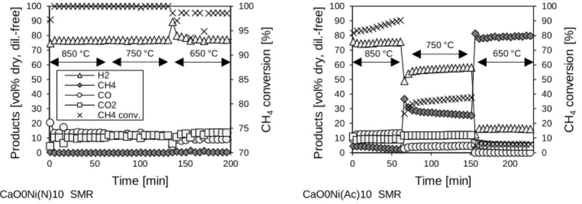
Les matériaux Ni mayenite sont testés pour vérifier leur réactivité en SMR, à trois niveaux de température (850-750-650 °C, 1 atm, WHSV = 0,24 NlCH4,in gcat-1 h-1, masse de
lit = 500 mg, rapport molaire vapeur/carbone = 3). Les catalyseurs SMR issus du nitrate de Ni ont toujours une très bonne réactivité, proche de l'équilibre thermodynamique ; d'autre part, la réactivité des catalyseurs dérivés de l’acétate de Ni est très inférieure, approchant l'inactivité à 650 °C, température du procédé de SESMR (Figure 5).
Figure 5 : Tests de SMR sur le catalyseur Ni-mayenite avec 10% en masse de Ni.
Pour cette raison, seuls les catalyseurs Ni mayenite dérivant du nitrate de Ni ont été utilisés pour des essais combinés avec des absorbants CaO mayenite. Les essais avec des lits séparés, c.-à-d. avec un catalyseur Ni mayenite (200 mg) précédant l’absorbant CaO mayenite (300 mg) selon le sens du flux de gaz, ont mis en évidence la fonctionnalité complète des deux types de matériaux dans des conditions choisies pour le procède SESMR (650 °C, 1 atm, WHSV = 0.60 NlCH4,in gcat-1 h-1, rapport molaire vapeur/carbone = 3).
Dans la configuration de mélange brut (mêmes conditions de tests qu’en lits séparés), un rôle préjudiciable de l’absorbant sur l'activité catalytique du catalyseur Ni mayenite a été détecté pour les catalyseurs à faible teneur en Ni (Figure 6).
Les deux preuves principales obtenues à partir des tests décrits ci-dessus sont
confirmées dans les tests SESMR sur CSCM (650 °C, 1 atm,
WHSV = 0,24 NlCH4,in gcat-1 h-1, masse du lit = 500 mg, rapport molaire vapeur/carbone =3).
En fait, tous les autres facteurs étant égaux :
• Les matériaux issus du nitrate de Ni sont nettement plus actifs que ceux issus de l’acétate de Ni ; 70 75 80 85 90 95 100 0 10 20 30 40 50 60 70 80 90 100 0 50 100 150 200 CH 4 co n v e rs io n [% ] P ro d u ct s [v o l% d ry , d il. -f re e ] Time [min] H2 CH4 CO CO2 CH4 conv. (a) 850 °C 750 °C 650 °C CaO0Ni(N)10 SMR 0 10 20 30 40 50 60 70 80 90 100 0 10 20 30 40 50 60 70 80 90 100 0 50 100 150 200 CH 4 co n v e rs io n [ % ] P ro d u ct s [v o l% d ry , d il. -f re e ] Time [min] (a) 850 °C 750 °C 650 °C CaO0Ni(Ac)10 SMR
• L'excès de CaO dans le CSCM réduit l'activité du Ni vis-à-vis du SMR : le CSCM issu de l’absorbant contenant un excès de 15 % en masse de CaO est totalement actif à la fois avec 3 % et 10 % en masse de Ni à partir du nitrate de Ni, tandis que pour 30 % ou 54 % en masse de CaO libre, une teneur massique en Ni de 10 % à partir du nitrate de Ni est suffisante pour garantir une réactivité complète en SESMR, mais 3 % en masse ne suffit pas (Figure 7).
Figure 6 : Tests de reformage avec les 2 types de matériaux dans des lits séparés et en mélange brut, en utilisant des catalyseurs de Ni-mayenite avec 3% ou 10% en masse de Ni à partir du nitrate de Ni et de l’absorbant de
CaO-mayenite avec 54% en masse d'excès de CaO.
Les matériaux sont également caractérisés après ces tests, de manière à mieux comprendre les phénomènes de réactivité observés : la DRX, les méthodes BET et BJH, l'apparition de la carbonatation (Réaction 3) confirmée par MEB dans tous les matériaux issus de tests SESMR à haute réactivité.
En se basant sur les résultats du SESMR de l'échelle du microréacteur, le CSCM le plus prometteur pour une applicabilité industrielle est CaO15Ni(N)10 (c'est-à-dire CaO mayenite avec 15% en masse d'excès de CaO, imprégnée du nitrate de Ni pour obtenir 10% en masse de Ni). 90 91 92 93 94 95 96 97 98 99 100 0 10 20 30 40 50 60 70 80 90 100 0 50 100 150 200 CH 4 co n v e rs io n [% ] P ro d u ct s [ v o l% d ry , d il. -f re e ] Time [min] H2 CH4 CO CO2 CH4 conv. (a)
CaO0Ni(N)10→CaO54 Separate beds
90 91 92 93 94 95 96 97 98 99 100 0 10 20 30 40 50 60 70 80 90 100 0 50 100 150 200 CH 4 co n v e rs io n [% ] P ro d u ct s [v o l% d ry , d il. -f re e ] Time [min]
CaO0Ni(N)10 + CaO54 Raw mixing
0 10 20 30 40 50 60 70 80 90 100 0 10 20 30 40 50 60 70 80 90 100 0 50 100 150 200 CH 4 co n v e rs io n [% ] P ro d u ct s [v o l% d ry , d il. -f re e ] Time [min] (c)
Figure 7 : Tests de SESMR sur CSCM issus des absorbants avec 54% et 15% en masse d'excès de CaO, imprégnés de Ni(NO3)2 · 6H2O pour obtenir 3% ou 10% en masse de Ni.
2.3
tude d'applicabilit industrielle
L'étude d'applicabilité industrielle est basée sur des tests multi cycliques SESMR/régénération de solides par un réacteur automatisé à lit fixe. Pour l'étape SESMR, les mêmes conditions utilisées pour les tests à l'échelle du microréacteur sur des CSCM sont adoptées, avec une mise à l'échelle sur la masse de lit de 6-7 g. Différents types de variation de température sont utilisés pour l'étape de régénération.
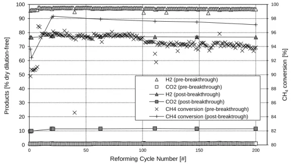
Dans un premier test, CaO15Ni(N)10 subit 205 cycles (durée totale 16 jours), avec régénération sous N2 pur (de 650 °C à 850 °C, 10 °C min-1 avec un palier à 850 °C),
donnant une performance très stable, en gardant son activité catalytique et ses fonctionnalités d’absorption, comme on peut le déduire de la différence constante entre les concentrations de produits avant et après la saturation de l’absorbant (Figure 8).
Par la suite, plus de 205 cycles sont effectués sur un échantillon frais du même matériau (durée totale 19 jours), avec des conditions de régénération plus dures sous CO2 pur (de
650 °C à 925 °C, 10 °C min-1 avec un palier à 925 °C), plus proche d'un processus à
l'échelle commerciale. Dans ce cas, la performance est moins satisfaisante, car le matériau présente une désactivation progressive pendant les 140 premiers cycles. Dans le but de restaurer l'activité catalytique pour les cycles restants, une forte réduction (850 °C, 30 min, 50 % en volume de H2 dans N2) est ajoutée après celle à 925 °C. Seule une récupération
0 10 20 30 40 50 60 70 80 90 100 0 10 20 30 40 50 60 70 80 90 100 0 50 100 150 200 CH 4 co n v e rs io n [% ] P ro d u ct s [v o l% d ry , d il. -f re e ] Time [min] CaO54Ni(N)10 0 10 20 30 40 50 60 70 80 90 100 0 10 20 30 40 50 60 70 80 90 100 0 50 100 150 200 CH 4 co n v e rs io n [ % ] P ro d u ct s [v o l% d ry , d il. -f re e ] Time [min] H2 CH4 CO CO2 CH4 conv. CaO54Ni(N)3 0 10 20 30 40 50 60 70 80 90 100 0 10 20 30 40 50 60 70 80 90 100 0 50 100 150 200 CH 4 co n v e rs io n [% ] P ro d u ct s [v o l% d ry , d il. -f re e ] Time [min] (g) CaO15Ni(N)10 0 10 20 30 40 50 60 70 80 90 100 0 10 20 30 40 50 60 70 80 90 100 0 50 100 150 200 CH 4 co n v e rs io n [ % ] P ro d u ct s [v o l% d ry , d il. -f re e ] Time [min] (f) CaO15Ni(N)3
partielle de production d’H2 et une augmentation modérée de la conversion du CH4 (Figure
8) sont récupérées.
Figure 8 : Tests multicycles SESMR/régénération sur CaO15Ni(N)10.
De plus, des tests multi cycliques sur des matériaux d'autres partenaires du projet ASCENT (IFE, CSIC et Marion Technologies) sont rapportés dans la thèse, synthétisés par agglomération mécanique d'un catalyseur industriel à base de Ni et d'un absorbant CaO mayenite. Ils ont été testés directement avec la régénération sous CO2 à 925 °C suivie d'une
réduction sous 50 % en volume de courant H2, à 850 °C, avec une performance satisfaisante
(Figure 9). 90 91 92 93 94 95 96 97 98 99 100 0 10 20 30 40 50 60 70 80 90 100 0 50 100 150 200 CH 4 co n v e rs io n [% ] P ro d u ct s [% d ry d ilu ti o n -f re e ] Cycle Number [#] H2 (pre-breakthrough) CO2 (pre-breakthrough) H2 (post-breakthrough) CO2 (post-breakthrough) CH4 conversion (pre-breakthrough) CH4 conversion (post-breakthrough)
CaO15Ni(N)3 test multicyclique SESMR/régéneration sous N2pur
0 10 20 30 40 50 60 70 80 90 100 0 10 20 30 40 50 60 70 80 90 100 0 50 100 150 200 CH 4 co n v e rs io n [% ] P ro d u ct s [% d ry d ilu ti o n -f re e ] Cycle Number [#] H2 (pre-breakthrough) CO2 (pre-breakthrough) H2 (post-breakthrough) CO2 (post-breakthrough) CH4 conversion (pre-breakthrough) CH4 conversion (post-breakthrough) 141
Un autre aspect important pour l'applicabilité industrielle, dans l'hypothèse d'une configuration de réacteur à double lit fluidisé à plus grande échelle, est la résistance mécanique des particules à l'attrition. Cette propriété est évaluée pour les matériaux les plus prometteurs, selon la norme ASTM D5757-11 (Méthode d'essai standard pour la détermination de l'attrition et l'abrasion des catalyseurs en poudre par Air Jets).
Figure 9 : Tests multicycles SESMR/régénération sur un matériel synthétisé par Marion Technologies (France) selon la méthode de IFE (Norvège) at CSIC (Espagne), autres partenaires du projet ASCENT.
3
Conclusion générale
Le procédé SESMR est d’un grand intérêt dans le cadre de la production d'hydrogène et la limitation des changements climatiques. L'utilisation de CSCM à base de Ni pour la catalyse du SMR et CaO pour la capture de CO2 est rapportée dans la littérature, en utilisant
des aluminates de calcium comme dispersants inertes. L'hypothèse d'un procédé à l'échelle industrielle réalisé dans un double lit fluidisé semble possible, car l’un des lits pourrait agir en tant que reformeur et l'autre comme régénérateur de l’absorbant par une variation de la température.
Une méthode de synthèse comprenant le mélange humide et l'imprégnation par voie humide s'est révélée efficace dans la production de catalyseurs de SMR Ni mayenite, des absorbants de CO2 CaO mayenite et des CSCM Ni CaO mayenite. Tous les matériaux
synthétisés partagent une morphologie microgranulaire, avec des vides internes répartis dans la gamme des méso- et macroporosité.
Pour Ni mayenite, le précurseur de Ni (nitrate ou acétate) influence principalement les propriétés texturales et la réductibilité. La réactivité en SMR est également très différente entre les deux cas, avec des matériaux dérivés de l’acétate de Ni présentant une activité catalytique très faible. 80 82 84 86 88 90 92 94 96 98 100 0 10 20 30 40 50 60 70 80 90 100 0 50 100 150 200 CH 4 co n v e rs io n [ % ] P ro d u ct s [ % d ry d ilu ti o n -f re e ]
Reforming Cycle Number [#]
H2 (pre-breakthrough) CO2 (pre-breakthrough) H2 (post-breakthrough) CO2 (post-breakthrough) CH4 conversion (pre-breakthrough) CH4 conversion (post-breaktrough)
Les résultats des essais sur Ni mayenite et CaO mayenite ont prouvé l'efficacité de cette dernière pour la capture de CO2 dans les conditions de SESMR, mais également un effet
néfaste sur l'activité du Ni lorsque les deux matériaux sont en contact direct et que la fraction de Ni est suffisamment faible.
Ces deux comportements principaux se répercutent sur l'efficacité du CSCM. Les tests en SESMR sur CSCM avec différents précurseurs de Ni, différentes teneurs en Ni et différents excès de CaO, ont mis en évidence que le nitrate de Ni et une faible teneur en CaO favorisent l'activité en SESMR.
Tout cela considéré, nous avons choisi Ni-CaO-mayeinite avec 10 % en masse de Ni provenant du nitrate ajouté par imprégnation humide sur un absorbant CaO mayenite avec 15 % en masse d'excès de CaO, pour une étude d'applicabilité industrielle, consistant en tests multicycles de SESMR/régénération. Différentes conditions de régénération donnent des résultats différents, car le matériau a des performances très bonnes et stables pour 205 cycles avec des régénérations sous N2 à 850 °C, alors qu'il subit une désactivation
progressive lorsqu'il est régénéré sous CO2 à 925 °C.
D'autre part, les matériaux provenant d'autres partenaires du projet ASCENT ont eu des performances satisfaisantes dans un test de 205 cycles avec régénération sous CO2 suivie
d'une période de réduction. Ceci a permis de valider une nouvelle étape vers le développement du procédé SESMR.
4
Références
[1] “ASCENT project,” 2014. [Online]. Available: http://www.ascentproject.eu/. [Accessed: 23-Sep-2016].
[2] L. Barelli, G. Bidini, F. Gallorini, and S. Servili, “Hydrogen production through sorption-enhanced steam methane reforming and membrane technology: A review,” Energy, vol. 33, no. 4, pp. 554–570, 2008.
[3] M. R. Cesário, B. S. Barros, C. Courson, D. M. A. Melo, and A. Kiennemann, “Catalytic performances of Ni-CaO-mayenite in CO2 sorption enhanced steam methane reforming,” Fuel Process. Technol., vol. 131, pp. 247–253, 2015. [4] C. S. Martavaltzi and A. A. Lemonidou, “Hydrogen production via sorption
enhanced reforming of methane: Development of a novel hybrid material-reforming catalyst and CO2 sorbent,” Chem. Eng. Sci., vol. 65, no. 14, pp. 4134– 4140, 2010.
[5] J. Meyer, J. Mastin, T.-K. Bjørnebøle, T. Ryberg, and N. Eldrup, “Techno-economical study of the Zero Emission Gas power concept,” Energy Procedia, vol. 4, pp. 1949–1956, 2011.
[6] B. Dou, C. Wang, Y. Song, H. Chen, B. Jiang, M. Yang, Y. Xu, “Solid sorbents for in-situ CO2 removal during sorption-enhanced steam reforming process : A review,” Renew. Sustain. Energy Rev., vol. 53, pp. 536–546, 2016.
[7] M. Shokrollahi Yancheshmeh, H. R. Radfarnia, and M. C. Iliuta, “High temperature CO2 sorbents and their application for hydrogen production by sorption enhanced steam reforming process,” Chemical Engineering Journal, vol. 283. pp. 420–444, 2016.
[8] A. Di Giuliano, J. Girr, R. Massacesi, K. Gallucci, and C. Courson, “Sorption enhanced steam methane reforming by Ni–CaO materials supported on mayenite,” Int. J. Hydrogen Energy, vol. 42, no. 19, pp. 13661–13680, 2017.
[9] I. Aloisi, A. Di Giuliano, A. Di Carlo, P. U. Foscolo, C. Courson, and K. Gallucci, “Sorption enhanced catalytic Steam Methane Reforming: Experimental data and simulations describing the behaviour of bi-functional particles,” Chem. Eng. J., 2016.
[10] F. Micheli, “Risparmio energetico e micro generazione distribuita, Clean Coal Technologies: CO2 capture,” University of L’Aquila and Universtiy of Strasbourg, 2014.
[11] I. Aloisi, N. Jand, S. Stendardo, and P. U. Foscolo, “Hydrogen by sorption enhanced methane reforming: A grain model to study the behavior of bi-functional sorbent-catalyst particles,” Chem. Eng. Sci., vol. 149, pp. 22–34, 2016.
Synthesis, characterization and industrial
applicability of Combined Sorbent-Catalyst
Materials for Sorption Enhanced Steam Methane
Reforming
Andrea DI GIULIANO
Supervisor Supervisor
Contents
List of figures ... v List of tables...xi List of symbols ... xiv Symbols ... xiv Greek letters ... xv List of acronyms ... xvi Chapter 1 Introduction to the research subject and issues ... 1 1.1 Climate change ... 1 1.1.1 Causes of climate change... 1 1.1.2 Evidences of climate change ... 3 1.1.3 Dealing with climate change ... 5 1.2 Hydrogen ... 7 1.2.1 Demand and production... 7 1.2.2 Hydrogen as a fuel ... 9 1.3 Carbon capture ... 11 1.3.1 CO2 capture technologies ... 11
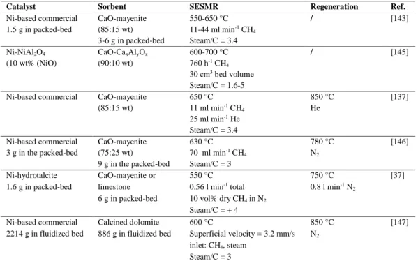
1.3.2 CaO-based high-temperature solid sorbents ... 13 1.4 Sorption enhanced steam methane reforming ... 18 1.4.1 2-Material systems in literature ... 19 1.4.2 Combined sorbent-catalyst materials in literature ... 21 1.4.3 Process configuration ... 23 1.5 Research issues ... 24 1.5.1 Ni fraction ... 25
ii
1.5.2 Ni salt precursor ...25 1.5.3 CaO influence on Ni ...26 1.5.4 Industrial applicability ...26 1.6 Thesis outline ... 27 Chapter 2 Materials and methods ...29 2.1 Materials synthesis ... 29 2.1.1 Wet mixing ...30 2.1.2 Wet impregnation ...30 2.1.3 Nomenclature and list of materials ...31 2.2 Characterization methods ... 31 2.2.1 Atomic emission spectroscopy ...32 2.2.2 X-ray diffraction ...32 2.2.3 Surface area and porosity analysis ...33 2.2.4 Scanning electron microscopy ...33 2.2.5 Transmission electron microscopy...34 2.2.6 Temperature programmed reduction ...34 2.2.7 Thermogravimetric analysis ...34 2.3 Reforming tests in microreactor ... 35 2.3.1 Reforming on Ni-mayenite ...37 2.3.2 Reforming on 2-material systems ...38 2.3.3 Reforming on Ni-CaO-mayenite ...38 2.3.4 Carbon balance ...38 2.4 Study for industrial applications ... 39 2.4.1 SESMR/regeneration multicycle tests...39 2.4.2 Mechanical properties evaluation ...42 2.5 Chemical equilibrium calculation ... 44 Chapter 3 As-synthesized materials ...45 3.1 Elemental composition ... 45 3.2 Crystalline phases ... 46 3.3 Morphology and topography ... 51 3.3.1 SEM ...51
iii 3.3.2 TEM ... 62 3.4 Textural properties ... 64 3.4.1 Shape of N2 adsorption and desorption isotherms ... 65
3.4.2 BET and BJH results ... 67 3.5 Reducibility properties ... 70 3.5.1 Crystalline phases after TPR ... 70 3.5.2 TPR profiles ... 74 3.6 Carbon capture properties ... 77 3.7 Conclusions ... 78 Chapter 4 Reactivity tests... 80 4.1 Results of chemical equilibrium calculation ... 80 4.2 Preliminary tests ... 80 4.3 Ni-mayenite reactivity ... 81 4.3.1 Results of reforming tests ... 81 4.3.2 Post-test characterization ... 83 4.4 Reactivity of 2-material systems ... 89 4.4.1 Results of separate beds tests ... 89 4.4.2 Separate beds: post-test characterization ... 90 4.4.3 Results of raw mixing tests ... 93 4.4.4 Raw mixing: post-test characterization ... 95 4.4.5 Comparison of spatial configurations ... 96 4.5 Reactivity of Ni-CaO-mayenite CSCM ... 100 4.5.1 Results of reforming tests ... 100 4.5.2 Post-test characterization ... 101 4.6 Conclusions ... 111 Chapter 5 Study for industrial applicability ... 113 5.1 SESMR/regeneration multicycle stability ... 113 5.1.1 Results of multicycle SESMR/regeneration tests ... 113 5.1.2 Post-test characterization ... 116 5.2 Mechanical properties evaluation ... 123 5.3 Conclusions ... 124
iv
General conclusions ...126 Addendum A Other materials in the ASCENT project ...130 A.1 Introduction ... 130 A.2 Materials and methods ... 130 A.3 Experimental results ... 131 Addendum B Validation of SESMR models ...134 B.1 Introduction ... 134 B.2 Validation of PGM ... 134 B.3 Validation of ADPFR dynamic model ... 136 B.3 ADPFR for SESMR/regeneration cycles ... 136 References ...138 Acknowledgements ...151
List of figures
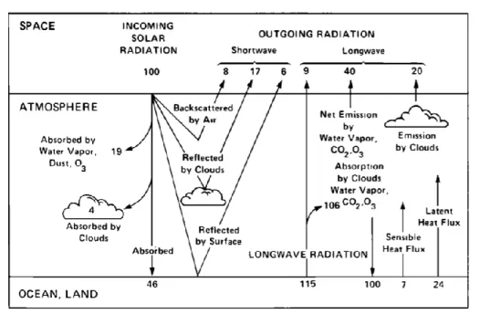
Figure 1.1: Schematic representation of the atmospheric heat balance (units are percent of incoming solar radiation): the solar fluxes are shown on the left-hand side, and the longwave (thermal infrared) fluxes are on the right-hand side [6,7] ... 2 Figure 1.2: CO2 emissions: historical series of CO2 level (a), with data until 2342 years ago
reconstructed from Vostok Ice Core indirect measurements [11], and those between 1958 and 2017 directly measured at Mauna Loa Observatory, Hawaii [1], magnified in (b); global net carbon flux
to atmosphere from land-usage change, data from [11] (c); global CO2 emissions from fossil-fuels
burning, data from [11] (d); ... 3
Figure 1.3: CH4 and N2O concentration series from Law Dome ice core records, data from [11].... 3
Figure 1.4: Change in global ocean-land surface temperature, relative to 1951-1980 average temperature (NASA's Goddard Institute for Space Studies) [1] ... 4 Figure 1.5: Mass variation of Antarctica and Greenland land ice (data from NASA's GRACE satellites) (a); change in sea level observed by satellites (data from NASA Goddard Space Flight Centre) (b) [1] ... 5 Figure 1.6: World total final energy consumption by region; “Asia” excludes China and countries belonging to the Organisation for Economic Co-operation and Development (OECD) of Asia; “Bunkers” includes international aviation and international marine bunkers [25] ... 6 Figure 1.7: World total final energy consumption by fuel; “Coal” includes coal, peat and oil shale; data for “Biofuels and waste” final consumption have been estimated for a number of countries; “Others” includes geothermal, solar, wind, heat, etc. [25] ... 6 Figure 1.8: Kondratieff cycles-long wave of prosperity, rolling 10-year yield on the S&P 500 since 1814 to March 2009 [30] ... 7 Figure 1.9: Estimated world H2 production sources (a) and usage (b) in 2008; data from [36] ... 8
Figure 1.10: Representation of a generic fuel cell with H+ ion conduction (picture from [69]) (a),
and of a SOFC (picture from [68]) (b) ... 9 Figure 1.11: Equilibrium curves for Reaction 1.5 ... 14
Figure 1.12: Representation of sintering phenomena in CaO (light grey) CaCO3 (dark grey) system
vi
Figure 1.13: Calcium aluminate phase diagram for humid conditions; Inset: section of the phase diagram around the mayenite composition (C12A7) for dry condition; phases in brackets are
considered as metastable [127] ... 17 Figure 1.14: Representation of [Ca12Al14O32]2O2«V»10 unit cell (a), with cage cantered oxygen ions
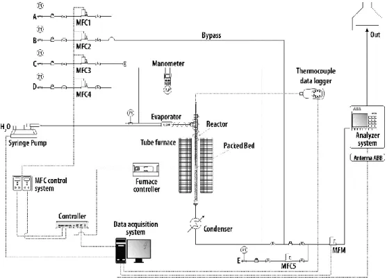
marked as O*, and schematization of possible oxygen ions conduction mechanisms (b) [127] ... 17 Figure 1.15: Simulation results for products of steam methane reforming (SR in figure) and sorption enhanced steam methane reforming (SER in figure), as a function of temperature; picture and simulative study from [137] ... 18 Figure 1.16: Typical breakthrough curve for a completely developed SESMR, picture from [141] ... 19 Figure 1.17: Representation of possible SESMR configurations based on the concept of solids circulation between two fluidized bed reactors [154] ... 23 Figure 2.1: Schematic view of microreactor scale packed bed experimental apparatus for reforming reactivity tests... 36 Figure 2.2: Schematic view of bench scale packed bed automated experimental apparatus for SESMR/regeneration multicycle tests (A: H2, B: CH4; C: N2; D: CO2; E: N2 dilution) ... 40
Figure 2.3: Control system of bench scale packed bed automated experimental apparatus for active bed temperature, by CARBOLITE MTF thermocouple; ... 40 Figure 2.4: Experimental apparatus for attrition tests ... 43 Figure 3.1: X-ray diffractograms for Ni-mayenite SMR catalyst, impregnated with Ni(N) (a) and Ni(Ac) (b), compared with corresponding parent material... 49 Figure 3.2: X-ray diffractograms for CSCM with nominal 3 wt% of Ni, compared with corresponding parent sorbents ... 50 Figure 3.3: X-ray diffractograms for CSCM with nominal 10 wt% of Ni, compared with corresponding parent sorbents ... 51 Figure 3.4: SEM micrographs at 2000x magnification of CaO0 (a) (b), CaO0Ni(N)3 (c) and CaO0Ni(Ac)3 (d) powder samples ... 53 Figure 3.5: SEM-EDS on external surfaces of CaO0 (a), CaO0Ni(N)3 (b), CaO0Ni(Ac)3 (c) ... 54 Figure 3.6: SEM-EDS elemental maps for embedded CaO0Ni(N)3 (a) and CaO0Ni(Ac)3 (b) ... 55 Figure 3.7: SEM micrographs at 2000x magnification of CaO15 (a) (b), CaO15Ni(N)3 (c), CaO15Ni(Ac)3 (d), CaO15Ni(N)10 (e), CaO15Ni(Ac)10 (f) powder samples ... 56 Figure 3.8: SEM micrographs at 2000x magnification of CaO54 (a) (b), CaO54Ni(N)3 (c), CaO54Ni(Ac)3 (d), CaO54Ni(N)10 (e), CaO54Ni(Ac)10 (f) powder samples ... 57 Figure 3.9: SEM-EDS on external surfaces of CaO15 (a), CaO15Ni(N)3 (b), CaO15Ni(Ac)3 (c), CaO15Ni(N)10 (d), CaO15Ni(Ac)10 (e) ... 58 Figure 3.10: SEM-EDS on external surfaces of CaO54 (a), CaO54Ni(N)3 (b), CaO54Ni(Ac)3 (c), CaO54Ni(N)10 (d), CaO54Ni(Ac)10 (e) ... 59
vii
Figure 3.11: SEM-EDS map for embedded CaO15Ni(N)3 (a), CaO15Ni(Ac)3 (b), CaO15Ni(N)10 (c), CaO15Ni(Ac)10 (d) ... 60 Figure 3.12: SEM-EDS map for embedded CaO54Ni(N)3 (a), CaO54Ni(Ac)3 (b), Cao54Ni(N)10 (c), CaO54Ni(Ac)10 (d) ... 61 Figure 3.13: TEM micrographs of as-synthesized CaO0Ni(N)10 (a, b) and CaO0Ni(Ac)10 (c, d) 62 Figure 3.14: TEM micrograph of as-synthesized CaO0Ni(Ac)10 (a) with graphical magnification of the zone within the white box (b), and comparison with a HRTEM micrograph of carbon black [192] (c) ... 63 Figure 3.15: TEM micrographs of as-synthesized CaO54Ni(N)10 (a) (b) ... 64 Figure 3.16: STEM-EDS analyses on as-synthesized CaO0Ni(N)10 (a) and CaO54Ni(N)10 (b) (c) ... 64
Figure 3.17: N2 adsorption/desorption data for CaO0Ni(N)3: isotherms (a) and their magnifications
in low (b) and high (c) relative pressure regions; BJH porosity assessment (d) ... 66
Figure 3.18: BET surface areas (SBET) (a) and BJH cumulative volumes (VBJH) (b) for Ni-mayenite
SMR catalysts, with corresponding CaO0 values as a reference ... 68 Figure 3.19: BET surface areas (SBET) (a) and BJH cumulative volumes (VBJH) (b) for CSCM
nominally containing 3 wt% of Ni and their parent CaO-mayenite sorbents ... 69 Figure 3.20: BET surface areas (SBET) (a) and BJH cumulative volumes (VBJH) (b) for CSCM
nominally containing 10 wt% of Ni and their parent CaO-mayenite sorbents ... 69 Figure 3.21: X-ray diffractograms for Ni-mayenite SMR catalyst, impregnated with Ni(N) (a) and Ni(Ac) (b), after TPR ... 72 Figure 3.22: X-ray diffractograms for Ni-CaO-mayenite CSCM, impregnated with Ni(N) (a) and Ni(Ac) (b), after TPR ... 73 Figure 3.23: TPR profiles of Ni-mayenite SMR catalysts; numbers on curves represent temperature in °C at the maximum of the corresponding reduction peak ... 75 Figure 3.24: TPR profiles of materials impregnated with 3 wt% and 10 wt% of Ni from Ni acetate, 3 wt% and 10 wt% of Ni from Ni nitrate; numbers on curves represent temperature in °C at the maximum of the corresponding reduction peak ... 76 Figure 3.25: Experimental results of TGA multicycle CO2 capture/regeneration tests ... 78
Figure 4.1: Preliminary reforming tests, according to procedure described in §2.3.3, on empty quartz reactor (a), CaO0 (b) and CaO54 (c); legend in (a) is valid for all diagrams ... 81 Figure 4.2: Results from reforming tests on CaO0Ni(N)10 (a, b), CaO0Ni(N)6 (c, d), CaO0Ni(N)4.5 (e, f), CaO0Ni(N)3 (g, h); first column descends from SMR-1 procedure, second column from SMR-2 procedures (§2.3.1); legend in (a) is valid for all diagrams ... 84 Figure 4.3: Results from reforming tests on CaO0Ni(Ac)10 (a, b), CaO0Ni(Ac)6 (c, d), CaO0Ni(Ac)4.5 (e, f), CaO0Ni(Ac)3 (g, h); first column descends from SMR-1 procedure, second column from SMR-2 procedures (§2.3.1); legend in (b) is valid for all diagrams... 85
viii
Figure 4.4: X-ray diffractograms for Ni-mayenite SMR catalysts impregnated with Ni(N) (a) and Ni(Ac) (b), after reforming tests by SMR-1 and SMR-2 procedures (§2.3.1)... 86 Figure 4.5: TEM micrographs of CaO0Ni(N)10 (a) (b) and CaO0Ni(Ac)10 (c) (d) after reforming tests by SMR-1 and SMR-2 procedures (§2.3.1) ... 87 Figure 4.6: STEM-EDS analyses on CaO0Ni(N)10 (a) (b) and CaO0Ni(Ac)10 (c) after reforming tests by SMR-1 and SMR-2 procedures (§2.3.1) ... 88 Figure 4.7: Results from reforming tests on 2-material systems in separate beds configuration counting CaO0Ni(N)10 as a catalyst, followed by CaO54 (a), CaO45 (b), CaO30 (c), CaO15 (d) as sorbents; legend in (a) is valid for all diagrams ... 90 Figure 4.8: Results from reforming tests on 2-material system in separate beds configuration counting CaO0Ni(N)3 as a catalyst followed by CaO54 as a sorbent ... 90 Figure 4.9: X-ray diffractograms for Ni-mayenite SMR catalysts impregnated with Ni(N) (a) and CaO-mayenite sorbents (b), after tests on 2-material systems in separate beds configuration; the material in the other bed during the tests is indicated within round brackets ... 92 Figure 4.10: Results from reforming tests on 2-material systems in raw mixing configuration counting CaO0Ni(N)10 as a catalyst, and CaO54 (a), CaO45 (b), CaO30 (c), CaO15 (d) as sorbents; legend in (b) is valid for all diagrams ... 94 Figure 4.11: Results from reforming tests on 2-material systems in raw mixing configuration counting CaO54 as a sorbent, and CaO0Ni(N)4.5 (a), CaO0Ni(N)3 (b) as catalysts; legend in (a) is valid for all diagrams ... 95 Figure 4.12: X-ray diffractograms for Ni-mayenite SMR catalysts impregnated with Ni(N) and CaO-mayenite sorbents, after SESMR tests raw mixing configuration ... 96 Figure 4.13: Magnification of results in Figure 4.7, from reforming tests on 2-material systems in separate beds configuration counting CaO0Ni10 as a catalyst, followed by CaO54 (a), CaO45 (b), CaO30 (c), CaO15 (d) as sorbents; equilibrium concentrations (“eq”) for SESMR at 650 °C, 1 atm come from Table 4.1; legend in (a) and (b) is valid for all diagrams ... 97 Figure 4.14: Magnification of results in Figure 4.10, from reforming tests on 2-material systems in raw mixing configuration counting CaO0Ni10 as a catalyst, and CaO54 (a), CaO45 (b), CaO30 (c), CaO15 (d) as sorbents; equilibrium values (“eq”) for SESMR at 650 °C, 1 atm come from Table 4.1; legend in (a) is valid for all diagrams ... 98 Figure 4.15: CH2,out and CCO,out breakthrough curves from reforming tests with separate beds (a) and
raw mixing (b) configurations, having CaO0Ni(N)10 as a catalyst ... 98 Figure 4.16: Results from reforming tests on 2-material systems in raw mixing configuration counting CaO0 as a solid diluent, and CaO0Ni(N)4.5 (a), CaO0Ni(N)3 (b), as catalysts; legend in (a) is valid for all diagrams ... 99 Figure 4.17: Results from reforming tests on CSCM from Ni(N): CaO54Ni(N)10 (a), CaO54Ni(N)3 (b), CaO45Ni(N)3 (c), CaO30Ni(N)10 (d), CaO30Ni(N)3 (e), CaO15Ni(N)10 (f), CaO15Ni(N)3 (g); legend in (b) is valid for all diagrams ... 102
ix
Figure 4.18: Results from reforming tests on CSCM from Ni(Ac): CaO54Ni(Ac)10 (a),
CaO54Ni(Ac)3 (b), CaO45Ni(Ac)3 (c), CaO30Ni(Ac)3 (d), CaO15Ni(Ac)10 (e),
CaO15Ni(Ac)3 (f); legend in (b) is valid for all diagrams ... 103 Figure 4.19: X-ray diffractograms for Ni-CaO-mayenite CSCM impregnated with Ni(N) after reforming tests ... 104 Figure 4.20: X-ray diffractograms for Ni-CaO-mayenite CSCM impregnated with Ni(Ac) after SESMR tests... 105 Figure 4.21: SEM micrographs at 2000x magnification of post-test CaO54Ni(N)10 (a), post-test CaO54Ni(N)3 (b), post-test CaO15Ni(N)10 (c), post-test CaO15Ni(N)3 (d) powder samples .... 107 Figure 4.22: SEM-EDS on external surfaces of post-test CaO54Ni(N)10 (a), CaO15Ni(N)10 (b), CaO15Ni(N)10 (c) ... 108 Figure 4.23: SEM-EDS map for embedded post-test CaO54Ni(N)10 (a), CaO15(Ni)10 (b) and CaO15Ni(N)3 (c) ... 109 Figure 4.24: TEM micrographs of post-test CaO54Ni(N)10 (a) (b) ... 110 Figure 4.25: STEM-EDS analyses on post-test CaO54Ni(N)10 (a) (b) ... 110 Figure 5.1: Overall experimental results of multicycle SESMR/regeneration tests with mild
regeneration conditions (N2 at 850 °C as a regeneration medium); having §2.4.1 as a reference, the
SESMR/regeneration loop 3 → 4 → 5 → 7 was performed 204 times, stopping the cycle 205 at the step 4 ... 114 Figure 5.2: CH2,out and CCO2,out breakthrough curves for cycles 5 and 200 from multicycle
SESMR/regeneration tests with mild regeneration conditions (N2 at 850 °C as a regeneration
medium) ... 115 Figure 5.3: Overall experimental results of multicycle SESMR/regeneration tests with severe
regeneration conditions (CO2 at 925 °C as a regeneration medium); having §2.4.1 as a reference, the
SESMR/regeneration loop 3 → 4 → 6 → 7 was performed for the first 140 cycles, the loop 3 → 4 → 6 → 8 from the loop 141 to the 204, stopping the 205 at the step 4; cycles from 112 to 126 are missing because of recording failure ... 116
Figure 5.4: CH2,out and CCO2,out breakthrough curves from multicycle SESMR/regeneration tests with
severe regeneration conditions (CO2 at 925 °C as a regeneration medium); having §2.4.1 as a
reference for the SESMR/regeneration loop 3 → 4 → 6 → 7 (cycles 1-140 (a) and the loop 3 → 4 → 6 → 8 (cycles 141-204 (b))... 116 Figure 5.5: X-ray diffractograms for CaO15Ni(N)10 after SESMR/regeneration multicycle tests ... 117 Figure 5.6: SEM micrographs of CaO15Ni(N)10 after SESMR/regeneration multicycle Test 1 at different magnifications: 500x (a) and (b), 2000x (c) and (d) ... 119 Figure 5.7: SEM micrographs of CaO15Ni(N)10 after SESMR/regeneration multicycle Test 2 at different magnifications of the same particle: 500x (a), 1000x (b), 2000x (c) and 8000x (d) ... 119 Figure 5.8: SEM-EDS on external surfaces of CaO15Ni(N)10 after SESMR/regeneration multicycle Test 1 (a) and Test 2 (b) ... 120
x
Figure 5.9: SEM-EDS map for embedded CaO15Ni(N)10 after SESMR/regeneration multicycle Test 1 ... 120 Figure 5.10: SEM-EDS map for embedded CaO15Ni(N)10 after SESMR/regeneration multicycle Test 2 ... 121 Figure 5.11: TEM micrographs of CaO15Ni(N)10 after SESMR/regeneration multicycle Test 1 122 Figure 5.12: STEM-EDS analyses on CaO15Ni(N)10 after SESMR/regeneration multicycle Test 1 ... 122 Figure 5.13: TEM micrographs of CaO15Ni(N)10 after SESMR/regeneration multicycle Test 2 123 Figure A.1: Overall experimental results of multicycle SESMR/regeneration test on the 2-material system in raw mixing configuration CaO30-IFE + Ni-comm; long reforming steps performed at cycles 1, 2, 40, 80, 140, 179, 208; all cycles with inlet steam/carbon molar ratio = 4 ... 132 Figure A.2: Overall experimental results of multicycle SESMR/regeneration test on Ca30Ni-IFE CSCM; long reforming steps performed at cycles 1, 2, 20, 21, 63, 111, 148, 200; first 7 cycles with inlet steam/carbon molar ratio = 3, all the rest with inlet steam/carbon molar ratio = 4 ... 132
Figure A.3: CH2,out and CCO2,out breakthrough curves from multicycle SESMR/regeneration tests on
the -2-material system in raw mixing configuration CaO30-IFE + Ni-comm (a) and the CSCM CaO30Ni-IFE (b) ... 133 Figure B.1: Experimental data (diamond dots) and PGM numerical simulations (solid lines) of CaO
conversion, (X), as a function of time, for multicycle CO2 capture/regeneration tests in TGA (§3.6);
for each simulated cycle (N), the initial average diameter of calcined sorbent grains (δCaO0) is pointed
out; data and picture from [101] ... 135 Figure B.2: CH2,out (LHS vertical axis) and CCO2,out , CCO,out , CCH4,out (RHS vertical axis) as functions
of time: measured values and ADPFR dynamic model simulations, for SESMR tests in microreactor scale on CaO30Ni(N)10 (a) and CaO54Ni(N)10 (b); data and picture from [101] ... 136 Figure B.3: CH2,out (LHS vertical axis) and CCO2,out , CCO,out , CCH4,out (RHS vertical axis) as functions
of time: measured SESMR breakthrough values and ADPFR dynamic model simulations, for multicycle SESMR/regeneration Test 1 in bench scale automated test rig on CaO15Ni(N)10, cycles 1 (a), 11 (b), 100 (c), 205 (d); legends in (a) and (b) are valid for all pictures; data and picture from [101]... 137
Figure B.4: Polynomial regression of δCaO0 used to fit SESMR breakthrough experimental data of
List of tables
Table 1.1: GHG characteristics: “anthropogenic sources” from [1]; numerical data from [10], with
Global Warming Potential at 100 year horizon (GWP100) defined as the number of times the referred
GHG is more warming than CO2 in 100 years ... 2
Table 1.2: Application of SOFC technology (adapted from [72]) ... 10 Table 1.3: Summary of different experimental conditions found in literature for 2-material systems ... 20 Table 1.4: Summary of different experimental conditions found in literature for CSCM ... 21 Table 2.1: List of synthesized materials ... 31 Table 2.2: PDF (Powder Diffraction Files) employed for crystalline phase identification in XRD, with 2 chosen for L calculations by Scherrer equation (Equation 2.1) ... 32 Table 3.1: Nominal elemental contents and ICP-AES experimental results for as-synthesized materials ... 46 Table 3.2: Average crystallite size (L) estimation by Scherrer equation (Equation 2.1) for as-synthesized materials main phases... 48 Table 3.3: Relative elemental percentage detected in STEM-EDS spot analysis; “Zone” refers to Figure 3.16 ... 64
Table 3.4: Measured BET surface areas (SBET), BJH cumulative volumes (VBJH) and averaged pore
diameters (Dav,BJH) for as synthesized materials ... 68
Table 3.5: Nature of TPR peaks in Ni-based catalysts on Ca/Al supports ... 71 Table 3.6: Average crystallite size (L) estimation by Scherrer equation (Equation 2.1) for main phases of materials after TPR ... 74 Table 3.7: TGA experimental results: maximum CO2 sorption capacity (ΓCO2) of CaO-mayenite
sorbents and CSCM, compared to nominal sorption capacities of calcinated materials ... 77 Table 4.1: Results from equilibrium simulations by CHEMCAD 6.5® according to specifications
in §0, for microreactor tests conditions (SESMR simulation with CaO/CH4 inlet molar ratio = 52)
xii
Table 4.2: Experimental CH4 and C from reforming activity tests on Ni-mayenite materials,
according to SMR-1 and SMR-2 procedures (§2.3.1); WHSV = 0.24 Nl h-1 g
cat-1; CH4 reported as a
unique number results from the average of experimental measurements, CH4 as a range indicates
the extreme values of a clearly increasing (↑) or decreasing (↓) trend ... 82 Table 4.3: Average crystallite size (L) estimation by Scherrer equation (Equation 2.1) for main phases of Ni-mayenite SMR catalysts after reforming tests by SMR-1 and SMR-2 procedures (§2.3.1) ... 86
Table 4.4: Experimental CH4 and C from reforming activity tests on 2-material systems in separate
beds configuration, according to §2.3.2 procedure; WHSV = 0.60 Nl h-1 g
cat-1; CH4 results from the
average of experimental measurements acquired in the considered time range ... 89 Table 4.5: Average crystallite size (L) estimation by Scherrer equation (Equation 2.1) for Ni-mayenite SMR catalysts impregnated with Ni(N), after tests on 2-material systems in separate beds configuration ... 91 Table 4.6: Average crystallite size (L) estimation by Scherrer equation (Equation 2.1) for CaO-mayenite sorbents, after tests on 2-material systems in separate beds configuration ... 91
Table 4.7: Measured BET surface areas (SBET), BJH cumulative volumes (VBJH) and averaged pore
diameters (Dav,BJH) for CaO-mayenite sorbents after tests in separate beds configuration; SBET,
VBJH and Dav,BJH are the percentage variations with respect to corresponding values in
as-synthesized state ... 91
Table 4.8: Experimental CH4 and C from reforming activity tests on 2-material systems in raw
mixing configuration (Group-1) according to §2.3.2 procedure; WHSV = 0.60 Nl h-1 g
cat-1; CH4 as
a unique number results from the average of experimental measurements, ranged CH4 indicates the
extreme values of a clearly decreasing trend (↓) ... 93
Table 4.9: Experimental CH4 and C from reforming activity tests on 2-material systems in raw
mixing configuration (Group-2) according to §2.3.2 procedure; WHSV = 0.60 Nl h-1 g
cat-1; CH4 as
a unique number results from the average of experimental measurements, ranged CH4 indicates the
extreme values of a clearly decreasing trend (↓) ... 94 Table 4.10: Average crystallite size (L) estimation by Scherrer equation (Equation 2.1) for samples after tests on 2-material systems in raw mixing configuration ... 95
Table 4.11: Experimental CH4 and C from reforming activity tests on 2-material systems in raw
mixing configuration counting Ni-mayenite and CaO0, according to §2.3.2 procedure;
WHSV = 0.60 Nl h-1 g
cat-1; CH4 as a unique number results from the average of experimental
measurements ... 99
Table 4.12: Experimental CH4 and C from reforming activity tests on Ni-CaO-mayenite CSCM,
according to procedure in §2.3.3; WHSV = 0.24 Nl h-1 g
CSCM-1; CH4 as a unique number results
from the average of experimental measurements, ranged CH4 indicates the extreme values of a
clearly increasing (↑) or decreasing (↓) trend ... 100 Table 4.13: Average crystallite size (L) estimation by Scherrer equation (Equation 2.1) for main phases of Ni-CaO-mayenite CSCM after reforming tests ... 105
xiii
Table 4.14: Measured BET surface areas (SBET), BJH cumulative volumes (VBJH) and averaged pore
diameters (Dav,BJH) for CSCM after reforming tests; SBET, VBJH and Dav,BJH are the percentage
variations with respect to corresponding values in as-synthesized state ... 106 Table 5.1: Average crystallite size (L) estimation by Scherrer equation (Equation 2.1) for main phases of CaO15Ni(N)10 after SESMR/regeneration multicycle tests ... 118
Table 5.2: Measured BET surface areas (SBET), BJH cumulative volumes (VBJH) and averaged pore
diameters (Dav,BJH) for CaO15Ni(N)10 after SESMR/regeneration multicycle tests; SBET, VBJH
and Dav,BJH are the percentage variations with respect to corresponding values in as-synthesized
state ... 118 Table 5.3: Results of attrition tests, according to procedure in §2.4.2; AJI(1 h) calculated by Equation 2.11, AJI(5 h) by Equation 2.12 and Recovery by Equation 2.13 ... 123
List of symbols
Symbols
cABBi,out outlet volumetric percentages measured by ABB system (Equation 2.10) [vol%]
cGC
i,out outlet species concentrations measured by GC (Equation 2.4) [vol%]
Ci,out products percentage on dry and inert-free basis (Equation 2.8)
[vol% dry, dil.-free]
Dav,BJH BJH averaged cylindrical pore diameter [nm]
Fi,in inlet molar flowrate of species “i” (Equation 2.4, Equation 2.5) [Nml min-1]
Fi,out outlet molar flowrate of species “i” (Equation 2.4, Equation 2.8) [Nml min-1]
Fout overall dry product flowrate (Equation 2.10) [Nml min-1]
K Scherrer equation (Equation 2.1) constant [#]
L average crystallite sizes, calculated by Scherrer equation (Equation 2.1) [nm]
m packed-bed mass (Equation 2.5 , Equation 2.6) [mg]
m(i) mass at the beginning of the ith cycle, TGA multicycle CO
2 capture test (Equation
2.3) [mg]
m0 mass at the end of cleaning, TGA CO2 capture test (Equation 2.2) [mg]
mfines(1 h) attrition tests recovered fines mass after 1 h (Equation 2.11) [g]
mfines(5 h) attrition tests recovered fines mass after 1 h (Equation 2.12, Equation 2.13) [g]
mr attrition test residual mass (Equation 2.13) [g]
ms attrition test initial sample mass (Equation 2.11, Equation 2.12, Equation 2.13)
[g]
NC,in total elemental C moles entering the reactor (Equation 2.9) [mol]
NC,out total elemental C moles leaving the reactor (Equation 2.9) [mol]
xv
OOx framework oxygen ion in mayenite
P BET experimental equilibrium pressure
P/P0 BET equilibrium relative pressure
P0 N2 vapour pressure at BET operating temperature
pCO2 CO2 partial pressure [atm]
pCO2,eq CO2 equilibrium partial pressure (Equation 1.1, Equation 1.2, Equation 1.3) [atm]
SBET BET surface area [m2 g-1]
T absolute temperature (Equation 1.1, Equation 1.2, Equation 1.3) [K]
t time [min]
t* breakthrough completion time [min]
VBJH BJH cumulative pore volume [cm3 g-1]
Vix empty cage in mayenite crystalline structure
Greek letters
wavelength of CuK1 radiation (Equation 2.1) [nm]
β FWMH of the reference peak (Equation 2.1) [rad]
γCO2(i) captured CO2 at the ith cycle, TGA multicycle CO2 capture test (Equation 2.3)
[gCO2 100 g-1calcined material]
ΓCO2 experimental maximum CO sorption capacity (Equation 2.2)
[gCO2 100 g-1calcined material]
δCaO0 average initial diameter of CaO grains in the PGM [nm]
C C-balance deviation in terms of percentage error (Equation 2.9) [%]
m 7 h mass increase, TGA CO2 capture test (Equation 2.2) [mg]
m(i) mass increase during the ith cycle, TGA multicycle CO
2 capture test (Equation
2.3) [mg]
SBET BET surface area percentage variation with respect to the as-synthesized state
[m2 g-1]
VBJH BJH cumulative pore volume percentage variation with respect to the
as-synthesized state [cm3 g-1]
2 Bragg angle (Equation 2.1) [rad]
CH4 CH4 conversion (Equation 2.7) [%]
List of acronyms
ADPFR Axial Dispersion Plug Flow Reactor
AISI American Iron and Steel Institute
AJI Air Jet Index
ASCENT Advanced Solid Cycles for Novel Efficient technologies
ASTM American Society for Testing and Materials
ASU Air Separation Unit
BET Brunauer-Emmett-Teller
BFB Bubbling Fluidized-Bed
BJH Barrett-Joyner-Halenda
BSE Back Scattering Electron
CCS Carbon Capture and Storage
CFB Circulating Fluidized Bed
CFBC Circulating Fluidized Bed Combustion
CFC ChloroFluoroCarbons
CLC Chemical Looping Combustion
CSCM Combined Sorbent-Catalyst Material
CSIC-ICB Consejo Superior de Investigaciones Cientificas – Instituto de Carboquimíca
DBFB Dual Bubbling Fluidized-Bed
EDS Energy Dispersive X-ray Spectrometry
EU European Union
FCC Fluid Catalytic Cracking
F-gases Fluorinated gases
xvii
GC Gas Chromatograph
GHG GreenHouse-Gases
GWP Global Warming Potential
HRTEM High-Resolution Transmission Electron Microscopy
ICDD International Centre of Diffraction Data
ICP-AES Inductively Coupled Plasma - Atomic Emission Spectroscopy
IFE Institutt For Energiteknikk
IGGC Integrated Gasifier Combined Cycle
IPCC United Nations Intergovernmental Panel on Climate Change
IUPAC International Union of Pure and Applied Chemistry
JCPDS Joint Committee on Powder Diffraction Standards
LHV Lower Heating Value
MEA MonoEthanolAmmine
NDIR Non-Dispersive InfraRed
Ni(Ac) Nickel Acetate tetrahydrate, Ni(CH3COO)2·4H2O
Ni(N) Nickel Nitrate hexahydrate, Ni(NO3)2·6H2O
Ni-WHSV Nickel Weight Hourly Space Velocity
PDF Powder Diffraction Files
PGM Particle Grain Model
PSA Pressure Swing Adsorption
SEM Scanning Electron Microscopy
SESMR Sorption Enhanced Steam Methane Reforming
SMR Steam Methane Reforming
SOFC Solid Oxide Fuel Cells
STEM Scanning Transmission Electron Microscopy
TCD Thermal Conductibility Detector
TEM Transmission Electron Microscopy
TGA Thermo-Gravimetric Analysis
TPD Temperature Programmed Desorption
TPR Temperature Programmed Reduction
USA United States of America
xviii
WHSV Weight Hourly Space Velocity
WI Wet Impregnation
WM Wet Mixing
Chapter 1
Introduction to the research
subject and issues
This chapter gathers information about the subject of this thesis, the sorption enhanced steam methane reforming, providing a background and raising the research issues faced in the next chapters.
1.1 Climate change
Earth climate has changed throughout history, for instance by seven glaciation in the last 650000 years, the last abruptly ending 7000 years ago, leading to the modern climate era and therefore to human civilization [1].
Nonetheless, the global warming trend measured since the second half of 20th century
is of noteworthy relevance, as it shows an unprecedented rate over decades to millennia and is extremely likely the result of contribution from human activities to the greenhouse-effect [2–5].
The causality relationship between human activities and climate-warming trend over the past century is acknowledged by the 97 % percent of climate scientists, and most of the leading scientific organizations worldwide have publicly endorsed this position [1,4].
1.1.1 Causes of climate change
The phenomenon popularly known as greenhouse-effect (Figure 1.1) consists in the trapping of long-wave (4-100 µm) radiations emitted by Earth’s surface, mainly brought about by water vapor, with a substantial contribution from CO2 and smaller contributions
by other gases, e.g. CH4, N2O, O3 [6]. The presence in Earth’s atmosphere of these
radiatively active gases, also known as greenhouse-gases (GHG), has made so far our planet habitable by life as we know it, since they rise the average global surface temperature by roughly 30 °C, as opposed to the estimated -15 °C in the absence of an atmosphere [6].
![Figure 1.2: CO 2 emissions: historical series of CO 2 level (a), with data until 2342 years ago reconstructed from Vostok Ice Core indirect measurements [11], and those between 1958 and 2017 directly measured at Mauna Loa Observatory, Hawaii [1], magni](https://thumb-eu.123doks.com/thumbv2/123doknet/14481171.524141/46.893.227.703.756.960/emissions-historical-reconstructed-indirect-measurements-directly-measured-observatory.webp)
![Figure 1.4: Change in global ocean-land surface temperature, relative to 1951-1980 average temperature (NASA's Goddard Institute for Space Studies) [1]](https://thumb-eu.123doks.com/thumbv2/123doknet/14481171.524141/47.893.216.692.246.517/figure-change-temperature-relative-temperature-goddard-institute-studies.webp)
![Figure 1.13: Calcium aluminate phase diagram for humid conditions; Inset: section of the phase diagram around the mayenite composition (C 12 A 7 ) for dry condition; phases in brackets are considered as metastable [127]](https://thumb-eu.123doks.com/thumbv2/123doknet/14481171.524141/60.893.175.732.137.588/calcium-aluminate-conditions-mayenite-composition-condition-considered-metastable.webp)
![Figure 1.17: Representation of possible SESMR configurations based on the concept of solids circulation between two fluidized bed reactors [154]](https://thumb-eu.123doks.com/thumbv2/123doknet/14481171.524141/66.893.203.701.519.818/figure-representation-possible-configurations-concept-circulation-fluidized-reactors.webp)