Official URL
https://doi.org/10.1007/978-3-030-46902-3_2
Any correspondence concerning this service should be sent
to the repository administrator:
[email protected]
This is an author’s version published in:
http://oatao.univ-toulouse.fr/26285
Open Archive Toulouse Archive Ouverte
OATAO is an open access repository that collects the work of Toulouse
researchers and makes it freely available over the web where possible
To cite this version: Singh, Neeraj and Ait Ameur, Yamine
and Méry, Dominique and Navarre, David and Palanque,
Philippe and Pantel, Marc Formal Development of
Multi-Purpose Interactive Application (MPIA) for ARINC 661. (2020)
In: 7th International Workshop on Formal Techniques for
Safety-Critical Systems (FTSCS 2019), 9 November 2019 - 9 November
2019 (Shenzhen, China).
Formal Development of Multi-Purpose Interactive
Application (MPIA) for ARINC 661
N. K. Singh1, Y. Aït-Ameur1, D. Méry2, D. Navarre3, P. Palanque3, and M. Pantel1 1
INPT-ENSEEIHT / IRIT, University of Toulouse, France
2
LORIA,Université de Lorraine & Telecom Nancy, Nancy, France
3
IRIT, Université de Toulouse, Toulouse, France
[email protected], [email protected], [email protected], [email protected], [email protected],
Abstract. This paper reports our experience for developing Human-Machine Interface (HMI) complying with ARINC 661 specification standard for inter-active cockpits applications using formal methods. This development relies on the FLUID modelling language, we have proposed and formally defined in the
FORMEDICIS1 project. FLUID contains essential features required for
speci-fying HMI. To develop the Multi-Purpose Interactive Applications (MPIA) use case, we follow the following steps: an abstract model of MPIA is written using the FLUID language; this MPIA FLUID model is used to produce an Event-B model for checking the functional behaviour, user interactions, safety properties, and interaction related to domain properties; the Event-B model is also used to check temporal properties and possible scenario using the ProB model checker; and finally, the MPIA FLUID model is translated to Interactive Cooperative Ob-jects (ICO) using the PetShop CASE tool to validate the dynamic behaviour, vi-sual properties and task analysis. These steps rely on different tools to check internal consistency along with possible HMI properties. Finally, the formal de-velopment of the MPIA case study using FLUID and its embedding into other formal techniques, demonstrates reliability, scalability and feasibility of our ap-proach defined in the FORMEDICIS project.
Keywords: Human-machine interface (HMI), formal method, refinement and proofs, Event-B, PetShop, verification, validation, animation.
1
Introduction
Developing a human-machine interface (HMI) is a difficult and time-consuming task [22] due to complex system characteristics and user requirements, which require antic-ipating human behaviour, system components and operational environment. Moreover, the design principles of HMI are different from traditional software development pro-cesses, including techniques and tools [29]. Considering every aspect of the HMI devel-opment process in a single framework, from requirement analysis to implementation, is
1
Funded by ANR (Agence nationale de la recherche), https://anr.fr/
a challenging task. Since a long time, formal methods play an important role for analyz-ing system interaction [5, 10, 11], and their use has been widely adopted in the current development process of HMI. Yet, to our knowledge there is no standard approach that can be used to formally develop and design a safety-critical HMI from spec to code.
The ongoing project, ANR-FORMEDICIS [14] where our work takes place, aims to propose a suite that can be used for developing and designing safety-critical HMIs. In this project, we develop a pivot modelling language, FLUID (Formal Language of User Interface Design), for the formal specification of HMI based on state transitions systems allowing to express requirements, assumptions, expectations, nominal and non nominal properties, and scenarios. Then, formal models in common languages can the be derived from a FLUID model for verification, validation, simulation and anima-tion. The derived formal models use theorem provers and model checkers for analyzing the different required functional properties, nominal and non nominal properties, and scenarios. In our work, we use the Event-B [1] modelling language for producing an abstract formal model and the PetShop CASE tool [27] for producing Interactive Co-operative Objects (ICO) model [23]. The produced models are analyzed with specific developed tools. Rodin [2] is used for Event-B models and PetShop for ICO models. The analyzed models provide feedback to the original FLUID model.
We propose to illustrate the FORMEDICIS approach applying it for the develop-ment of a complex case study issued from aircraft cockpit design: MPIA (Multi-Purpose Interactive Applications). First, we develop a FLUID model for MPIA and then we gen-erate an Event-B model and an ICO model from the developed FLUID model. In this development, we begin by specifying different MPIA components, including functional behaviour, states, assumptions, expectations, interactions, properties and scenarios. The embedding of the formal FLUID development of MPIA in Event-B preserves the re-quired behaviour in the developed model. In the generated model, we prove important properties, such as functional behaviour, user interactions, safety properties, and inter-action related domain properties. We use the ProB model checker tool [21] to analyze and validate the developed models, and to check temporal properties and possible sce-nario for HMI. In the ICO model, we provide the dynamic behaviour of MPIA. The developed ICO specification fully describes the potential interactions that users may have with the application. It covers both input and output aspects related to users. In the ICO formalism, there are four components: a cooperative object which describes the behaviour of the object, a presentation part, activation function and rendering function to link between the cooperative object and the presentation part.
This paper is organized as follows. Section 2 presents the required background. Section 3 describes the FLUID language. Section 4 provides the selected MPIA case study. section 5 presents a formal development of the case study in FLUID. Section 6 and Section 7 illustrates the formal developments of the FLUID model in Event-B and PetShop, respectively. In Section 8, we provide an assessment of our work and Section 9 presents related work. Finally, Section 10 concludes the paper with future work.
2
Preliminaries
2.1 The Modelling Framework: Event-B
This section describes the modelling components of the Event-B language [1]. The Event-B language contains two main components, context for describing the static prop-erties of a system using carrier sets s, constants c, axioms A(s, c) and theorems Tc(s, c),
and machine for describing behavioural properties of a system using variables v,
invari-ants I(s, c, v), theorems Tm(s, c, v), variants V (s, c, v) and events evt. A context can
be extended by another context, a machine can be refined by another machine and a machine can use sees relation to include other contexts.
An Event-B model is characterized by a list of state variables possibly modified by a list of events. A set of invariants I(s, c, v) shows typing invariants and the required safety properties that must be preserved by the defined system. A set of events presents a state transition in which each event is composed of guard(s) G(s, c, v, x) and action(s) v : |BA(s, c, v, x, v′). A guard is a predicate, built on state variables, for enabling the event’s action(s). An action is a generalized substitution that describes the ways one or several state variables are modified by the occurrence of an event.
The Event-B modelling language supports the correct by construction approach to design an abstract model and a series of refined models for developing any large and complex system. Refinements, introduced by the REFINES clause, transform an ab-stract model to a more concrete version by modifying the state description. A refine-ment allows modelling a system gradually by introducing safety properties at various refinement levels. New variables and new events may be introduced in a new refinement level. These refinements preserve the relation between the refining model and its corre-sponding refined concrete model, while introducing new events and variables to specify more concrete behavior of a system. The defined abstract and concrete state variables are linked by introducing the gluing invariants. The generated proof obligations ensure that each abstract event is correctly refined by its concrete version.
Rodin [2] is an integrated development environment (IDE) for the Event-B mod-elling language based on Eclipse. It includes project management, stepwise model de-velopment, proof assistance, model checking, animation and automatic code generation. Once an Event-B model is modelled and syntactically checked on the Rodin platform then a set of proof obligations (POs) is generated using the Rodin proof engine. Event-B supports different kinds of proof obligations, such as invariant preservation, non-deterministic action feasibility, guard strengthening in refinements, simulation, variant, well-definedness etc. More details related to the modelling language and proof obliga-tions can be found in [1].
2.2 ICO Notation and PetShop CASE Tool
This section recalls the main features of the Interactive Cooperative Objects (ICOs) formal description technique used for modelling software of interactive systems. ICO is dedicated to the specification of interactive systems [23]. It uses concepts borrowed from the object-oriented approach (dynamic instantiation, classification, encapsulation,
inheritance, client/server relationship) to describe the structural or static aspects of sys-tems, and uses high-level Petri nets to describe their dynamic or behavioural aspects.
ICOs are dedicated to the modelling and the implementation of event-driven inter-faces, using several communicating objects to model the system, where both behavior of objects and communication protocol between objects are described by the Petri net dialect called Cooperative Objects (CO). In the ICO formalism, an object is an entity featuring four components: a cooperative object which describes the behavior of the object, a presentation part (i.e. the graphical interface), and two functions (the activa-tion funcactiva-tion and the rendering funcactiva-tion) which make the link between the cooperative object and the presentation part.
An ICO specification fully describes the potential interactions that users may have with the application. The specification encompasses both the "input" aspects of the interaction (i.e. how user actions impact on the inner state of the application, and which actions are enabled at any given time) and its "output" aspects (i.e. when and how the application displays information relevant to the user). These aspects are expressed by means of the activation function (for input) and the rendering function (for output). ICOs description do not integrate graphical rendering of information and objects. This is usually delegated to Java code or to other description techniques such as UsiXML [9]. The ICO notation is fully supported by a CASE tool called PetShop [27]. All the models presented in the next sections have been edited and simulated using PetShop. Some formal analysis is also supported by the tool but limited to the underlying Petri net, removing the specificities brought by the high-level Petri net model.
3
FLUID Language
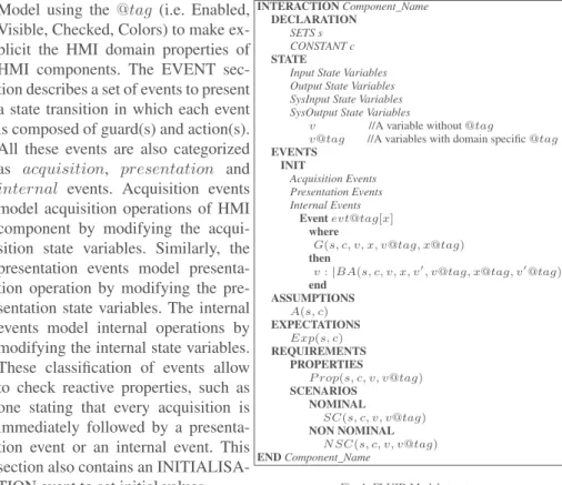
The FLUID language2 developed in the FORMEDICIS project is organized in three main parts to describe static, dynamic and requirements. The static part defines type definition, constant, sets and the required features for interactions. The dynamic part de-fines a state-transition system for describing interactive system. The requirements part expresses the required behaviour, including user tasks and scenarios. A FLUID model is an INTERACTION module which is composed of six sections (see Fig. 1). The first three sections, DECLARATION, ASSUMPTIONS and EXPECTATIONS, describe the static part of a model. The following STATE and EVENT sections describe the dynamic part of a model, and the last REQUIREMENT section describes the requirement part of a model. The DECLARATION section allows to define new typing information that can be used to describe a HMI model.
The typing information may depend on generic and abstract types, such as sets, constants, enumerated sets, and natural and integer numbers. The STATE section declares a list of variables, which are classified as Input, Output, SysInput and SysOutput. The interactions between system and user can be characterized by the Input and Output variables while the interactions between system components can be characterized by SysInput and SysOutput variables. Note that all these variables can be tagged using domain knowledge concepts borrowed from an external knowledge.
Model using the @tag (i.e. Enabled, Visible, Checked, Colors) to make ex-plicit the HMI domain properties of HMI components. The EVENT sec-tion describes a set of events to present a state transition in which each event is composed of guard(s) and action(s). All these events are also categorized as acquisition, presentation and internal events. Acquisition events model acquisition operations of HMI component by modifying the acqui-sition state variables. Similarly, the presentation events model presenta-tion operapresenta-tion by modifying the pre-sentation state variables. The internal events model internal operations by modifying the internal state variables. These classification of events allow to check reactive properties, such as one stating that every acquisition is immediately followed by a presenta-tion event or an internal event. This section also contains an INITIALISA-TION event to set initial values.
INTERACTION Component_Name DECLARATION
SETS s CONSTANT c
STATE
Input State Variables Output State Variables SysInput State Variables SysOutput State Variables
v //A variable without@tag
v@tag //A variables with domain specific@tag EVENTS INIT Acquisition Events Presentation Events Internal Events Event evt@tag[x] where G(s, c, v, x, v@tag, x@tag) then
v: |BA(s, c, v, x, v′, v@tag, x@tag, v′@tag)
end ASSUMPTIONS A(s, c) EXPECTATIONS Exp(s, c) REQUIREMENTS PROPERTIES P rop(s, c, v, v@tag) SCENARIOS NOMINAL SC(s, c, v, v@tag) NON NOMINAL N SC(s, c, v, v@tag) END Component_Name
Fig. 1: FLUID Model structure
The ASSUMPTIONS section introduces the required assumptions related to en-vironment that includes the user and machine agents. These assumptions can be ex-pressed as logical properties to express HMI properties. The EXPECTATIONS section describes prescriptive statements that are expected to be fulfilled by parts of the envi-ronment of an interactive system. Note that the assumptions and expectations can be expressed in the same way, but both are different. The REQUIREMENTS section is divided into two subsections, known as PROPERTIES and SCENARIOS. The PROP-ERTIES section describes in logic all the required properties of an interactive system that must be preserved by a defined system. The SCENARIOS section describes both nominal and non-nominal scenarios using algebraic expressions, close to CTT [28], for analyzing possible acceptable and non-acceptable interactions.
4
MPIA Case Study
ARINC 661 is a standard, designed by the Airlines Electronic Engineering Committee (AEEC), for normalizing the definition of a Cockpit Display System (CDS) [6] and it provides guidelines for developing the CDS independently from the aircraft systems. The CDS provides graphical and interactive services to use applications within the flight deck environment. It controls user-system interaction by integrating input devices, such as keyboard and mouse.
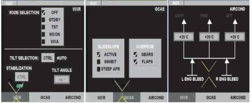
We present the Multi-Purpose Interactive Application (MPIA) that complies with ARINC 661 standard to demonstrate our formal modelling and verification approach considering several software engineering concepts related to HMI. Fig. 2 depicts MPIA which is a real User Application (UA) for handling several flight parameters. This ap-plication contains a tabbed panel with three tabs, WXR for managing weather radar in-formation, GCAS for Ground Collision Avoidance System parameters and AIRCOND for dealing with air conditioning settings. A crew member is allowed to switch to any mode (see Fig. 2) using tabs. These tabs have three different applications which can be controlled by the pilot and the co-pilot using any input devices.
The MPIA window of any tab is composed of three main parts: information area,
workspace areaand menu bar. The information area is the top bar of any tab that splits in two parts for displaying the current state of the application on the left part and the er-ror messages, actions in progress or bad manipulation when necessary on the right part. The workspace area shows changes according to the selected interactive control panel. For example, WXR workspace displays all the modifiable parameters of the weather radar sensor, GCAS workspace shows some of the working modes of GCAS, and AIR-COND workspace displays the selected temperature inside an aircraft. The menu bar area contains three tabs for accessing the interactive control panels related to WXR, GCAS and AIRCOND.
Fig. 2: Snapshots of the MPIA (from left to right: WXR, GCAS and AIRCOND)
5
Formal Development of MPIA in FLUID
We present a formal description of MPIA in FLUID. Due to space limitation, we show only the FLUID model of weather radar information (WXR). The other HMI widgets, such as GCAS and AIRCOND, of MPIA are developed in a similar way.
5.1 Declaration
For modelling the HMI of WXR in FLUID, we define a set of enumerated datatypes and a constant to represent system properties in the DECLARATION clause. Three enu-meration sets are: WXR_MODE_SELC_SET for modes, WXR_TILT_STAB-_MSG for messages, and WXR_ACTIONS for actions. A constant WXR_ANGL_RANG is defined a range of tilt angle.
5.2 State
In WXR model, we define several state variables in STATE clause for representing
Input, Output, SysInputand SysOutput states. There are four variables to represent input or acquisition states and six variables to represent output or presentation states. All these variables associated with tag information (Input, Enabled, Visible, Checked, etc.) are defined with the given datatypes. Note that the associated tags are defined in a HMI metadata library, including types.
5.3 Events
To model the functional inter-active behaviour of WXR, we define a set of events, including an INIT event in the EVENT clause. The INIT event only sets initial value for each state variable while the other events are used to model possible HMI behaviour (state changes). In the INIT event, we show initial state of an acquisition variable (A_M odeSelection) and a presentation variable (P _checkM ode), including tag details. Other state variables and their associated tags are initialized in a similar way.
DECLARATION
// WXR Mode enumeration set
TYPE WXR_MODE_SELC_SET = enumeration (M_OFF, STDBY, TST, WXON, WXA)
// WXR Tilt and Stabilisation message enumeration set
TYPE WXR_TILT_STAB_MSG = enumeration (ON, OFF, AUTO, MANUAL)
// WXR Tilt angle range
CONSTANT WXR_ANGL_RANG = [ -15 .. 15 ]
// WRX actions
TYPE WXR_ACTIONS = enumeration (TILT_CTRL, STAB_CTRL)
STATE Section // Acquisition states
A_ModeSelection@{Input, Checked} : WXR_MODE_SELC_SET// Mode state
A_TiltSelection@{Input, Enabled} : WXR_TILT_SELC_SET// Tilt state
A_Stabilization@{Input, Enabled} : WXR_STAB_SELC_SET// Stabilization state
A_TiltAngle@{Input,Enabled} : WXR_ANGL_RANG // Tile angle state
. . . // Presentation states
// Radio buttons presentation states
P_checkMode@{Output, Checked} : WXR_MODE_SELC_SET→ BOOL
// CTRL tilt button presentation state
P_ctrlModeTilt_Button@{Output, Enabled} : WXR_ACTIONS
// CTRL tilt label presentation state
P_ctrlModeTilt_Label@{Output, Visible} : WXR_TILT_STAB_MSG
// CTRL stablization button presentation state
P_ctrlModeStab_Button@{Output, Enabled} : WXR_ACTIONS
// CTRL stablization label presentation state
P_ctrlModeStab_Label@{Output, Visible} : WXR_TILT_STAB_MSG
// Tilt angle value in the presentation state
P_TiltAngle@{Output, Enabled} : WXR_ANGL_RANG
The FLUID model contains 6 acquisition events in the acquisition clause, and 7 presentation events in the presentation clause. Here, we only show two acquisition events (modeSelection and tiltCtrl) and one presentation event (checkM ode) to demonstrate the modelling concepts related to HMI. Note that the name of acquisition event is followed by@Acquisition, and the name of presentation event is followed by @P resentation. The semantics of FLUID language guarantee that an acquisition event is always followed by the corresponding presentation event or internal event to express an interaction behaviour composed of several atomic events related to input, output etc. The event modeSelection is allowed to select any mode to the input or acquisition state (A_M odeSelection) from the workspace area of WXR (see Fig. 2). Note that only input variable and associated tag value are updated through event’s actions. Similarly, the event tiltCtrl is used to select a possible action to the input or acquisition state (A_T iltSelection). In this event, the actions are also used to update input variable, including tag. The event checkM ode presents the state changing behaviour of a widget (radio) defined in the workspace area (see Fig. 2).
The guard of this event state that the selected widget option, acquired by the acquisi-tion state (A_M odeSelecacquisi-tion) should not be Checked. The acacquisi-tion of this event shows the selected option as T RU E and the other options as F ALSE, and the associated tag is updated as T RU E. Other events related to acquisition and presentation are modelled in a similar way.
5.4 Requirements
The REQUIREMENTS clause of FLUID model contains a set of required proper-ties, and nominal and non nominal sce-narios expressing expected, respectively unexpected, behaviors. In our model, we define 8 safety properties to check the correctness of HMI model. The first safety property (P rop_1) states that al-ways a single option is selected from the workspace area (see Fig. 2). The sec-ond property (P rop_2) states that the acquisition event modeSelection is al-ways followed by the presentation event checkM ode. Other properties are defined to check the interaction behaviour of HMI components. We define a nominal sce-nario SC_1 and a non nominal N SC_1 which are started by the INIT event that is followed by the mode selection, tilt selec-tion, stabilization and tilt angle activities using interleaving operator (||). Note that each activity is composed of acquisition and presentation events in a sequential or-der (;). In addition, if there are more than one possible events of acquisition, or pre-sentation then we use optional operator[ ] to compose them. To simulate these sce-narios iteratively, we use∗ operator. Note that the nominal scenario shows possible expected HMI interactions that may oc-cur, while the non nominal scenario shows unexpected HMI interaction that must not occur. EVENTS Section // Initialisation Event INIT = A_ModeSelection:= OFF A_ModeSelection@Checked:= TRUE . . .
// Only OFF mode is selected at initialisation
P_checkMode:= {i 7→ j | i ∈ WXR_MODE_SELC_SET ∧ j = FALSE } ∪ { M_OFF 7→ TRUE } )\{M_OFF 7→ FALSE} P_checkMode@Checked := TRUE
. . .
// ACQUISITION Events
// Any mode is allowed to select from WXR to acquisition state
Event modeSelection@Acquisition = ANY mode WHERE mode : WXR_MODE_SELC_SET THEN A_ModeSelection:= mode A_ModeSelection@Checked:= TRUE END
// The tilt selection model : AUTO or MANUAL (to acquisition state). // The CTRL push-button allows to swap between the two modes
Event tiltCtrl@Acquisition = ANY
n_tilt WHERE
n_tilt : WXR_ACTION∧ n_stab = TILT_CTRL ∧ n_stab@Enabled = TRUE THEN A_TiltSelection:= n_tilt A_TiltSelection@Enabled:= TRUE END Event stabCtrl@Acquisition = . . . Event tiltAngle@Acquisition = . . . Event tiltAngle_Greater_15@Acquisition = . . . Event tiltAngle_Less_15@Acquisition = . . . // PRESENTATION Events
// Presentation of radio button: Only selected mode will be checked as TRUE
Event checkMode@Presentation = WHEN
A_ModeSelection@Checked = TRUE THEN
P_checkMode:=( {i7→ j | i ∈ WXR_MODE_SELC_SET ∧ j = FALSE }∪{ A_ModeSelection 7→ TRUE } )\ {A_ModeSelection7→ FALSE} P_checkMode@checked := TRUE END Event ctrlModeTilt_Auto@Presentation = . . . Event ctrlModeTilt_Manual@Presentation = . . . Event ctrlModeStab_On@Presentation = . . . Event ctrlModeStab_Off@Presentation = . . . Event tiltAngle_True@Presentation = . . . Event tiltAngle_False@Presentation = . . . REQUIREMENTS Section PROPERTIES
Prop1 :∀ m1,m2· m1∈ WXR_MODE_SELC_SET ∧ m2∈ WXR_MODE_SELC_SET ∧ m17→ TRUE ∈ prj1(prj1(P_checkMode)) ∧ m27→ TRUE ∈ prj1(prj1(P_checkMode)) ⇒ m1=m2
Prop2 :G(e(modeSelection@Acquisition)⇒ X (e(checkMode@Presentation) )))
Prop3 :(e(tiltAngle@Acquisition)⇒ (e(tiltAngle_True) or e(tiltAngle_False@Presentation))) Prop4 :{P_ctrlModeTilt_Label = (AUTO7→Output)7→TRUE ⇒ P_ctrlModeStab_Label = (OFF7→Output)7→TRUE} Prop5 :{P_ctrlModeTilt_Label = (MANUAL7→Output)7→TRUE ⇒ P_ctrlModeStab_Label = (ON7→Output)7→TRUE} Prop6 :{P_ctrlModeTilt_Label = (AUTO7→Output)7→TRUE ⇒ P_ctrlModeStab_Button = (STAB_CTRL7→Output)7→FALSE} Prop7 :{P_ctrlModeTilt_Label = (MANUAL7→Output)7→TRUE ⇒ P_ctrlModeStab_Button = (STAB_CTRL7→Output)7→TRUE} Prop8 :{P_ctrlModeTilt_Label = (MANUAL7→Output)7→TRUE ⇒ P_TiltAngle = (107→Output)7→TRUE}
SCENARIOS NOMINAL
SC_1 = INIT; ((modeSelection@Acquisition; checkMode@Presentation)
|| (tiltCtrl@Acquisition; (ctrlModeTilt_Auto@Presentation [] ctrlModeTilt_Manual@Presentation)) || (stabCtrl@Acquisition; (ctrlModeStab_On@Presentation [] ctrlModeStab_Off@Presentation)) || (tiltAngle@Acquisition [] tiltAngle_Greater_15@Acquisition [] Evt_tiltAngle_Less_15@Acquisition); (tiltAngle_True@Presentation [] Evt_tiltAngle_False@Presentation))∗
NON NOMINAL
SC_1 = INIT; ((modeSelection@Acquisition; checkMode@Presentation)
In this model, the SC_1 shows possible interactions of WXR HMI while the NSC_1 shows some of the impossible WXR HMI interactions, for example, if an acquisition of tilt selection is followed by the auto mode presentation then the acquisition of stabiliza-tion or tilt angle is not possible.
6
Exploring the MPIA FLUID Model in Event-B
A FLUID model is translated into Event-B as follows: 1) An INTERACTION FLUID component is interpreted as a machine and a context in Event-B; 2) All the constants and sets defined in a FLUID model correspond to an Event-B context; 3) FLUID states are translated into a set of variables in an Event-B model, and the variable typing is also defined as typing invariants of Event-B; 4) FLUID initialisation event and the other events are transformed into an Event-B initialisation event and to a set of events; and 5) The properties of FLUID model are translated into Event-B invariants. Note that some properties are translated into temporal properties using LTL or CTL formula in ProB to check system properties and to animate our models. Finally, the produced Event-B model is checked within the Rodin environment and all the defined safety properties proved successfully.
6.1 Model
Context. In the translated model, two different contexts are defined, the first one con-tains domain specific information related to HMI while the other one is used to define static properties of HMI. In the domain specific context, we define possible tag informa-tion for different widgets, for example, we define an enumerated set HMI_TAG to state the tag properties of HMI states in daxm1. In addition, we also define three constants, CHECKED, VISIBLE and ENABLED, as boolean to define tag information for HMI widgets (daxm2). In the second context, we declare three enumerated sets, WXR_-MODE_SELC_SET for modes, WXR_WXR_-MODE_SELC_SET for a set of messages, and WXR_ACTIONS for a set of actions to specify the MPIA components using axioms (axm1-axm3). Enumerated sets are defined using the partition statement. We also de-clare a constant, WXR_ANGL_RANG, to specify a range (-15 .. +15) of the tilt angle in axm4.
daxm1 : partition(HM I_T AG, {Input}, {Output}, {SysInput}, {SysOutput}) daxm2 : CHECKED = BOOL ∧ V ISIBLE = BOOL ∧ EN ABLED = BOOL
axm1 : partition(W XR_M ODE_SELC_SET , {M _OF F }, {ST DBY }, {T ST }, {W XON }, {W XA}) axm2 : partition(W XR_T ILT _ST AB_M SG, {AU T O}, {M AN U AL}, {ON }, {OF F })
axm3 : partition(W XR_ACT ION S, {T ILT _CT RL}, {ST AB_CT RL}) axm4 : W XR_AN GL_RAN G = −15 .. 15
Machine. An Event-B machine is also derived from the FLUID model that is translated straightforward. The generated Event-B model shows the HMI behaviour and possible interactions with MPIA widgets. In this model, we introduce 11 state variables (inv1 -inv11) to model the dynamic behaviour of the system. All these variables are similar to the FLUID model and are declared as tuple using cartesian product (×). Note that each variable contains state information and tag information related to HMI. In the
current model, we introduce a safety property saf1 (see property P rop1) to state that there is only one mode selected from the MODE SELECTION of WXR. Note that other properties (P rop2 - P rop8) of the FLUID model are defined later in the ProB model checker.
inv1 : A_M odeSelection ∈ W XR_M ODE_SELC_SET × HM I_T AG × CHECKED inv2 : A_T iltSelection ∈ W XR_ACT ION S × HM I_T AG × EN ABLED
inv3 : A_Stabilization ∈ W XR_ACT ION S × HM I_T AG × EN ABLED inv4 : A_T iltAngle ∈ W XR_AN GL_RAN G × HM I_T AG × EN ABLED
inv5 : P _checkM ode ∈ (W XR_M ODE_SELC_SET → BOOL) × HM I_T AG × CHECKED inv6 : P _ctrlM odeT ilt_Button ∈ W XR_ACT ION S × HM I_T AG × EN ABLED inv7 : P _ctrlM odeT ilt_Label ∈ W XR_T ILT _ST AB_M SG × HM I_T AG × V ISIBLE inv8 : P _ctrlM odeStab_Button ∈ W XR_ACT ION S × HM I_T AG × EN ABLED inv9 : P _ctrlM odeStab_Button ∈ W XR_ACT ION S × HM I_T AG × EN ABLED inv10 : P _ctrlM odeStab_Label ∈ W XR_T ILT _ST AB_M SG × HM I_T AG × V ISIBLE inv11 : P _T iltAngle ∈ W XR_AN GL_RAN G × HM I_T AG × EN ABLED
saf1 : ∀m1, m2·m1 ∈ W XR_M ODE_SELC_SET ∧ m2 ∈ W XR_M ODE_SELC_SET ∧
m1 7→ T RU E ∈ prj1(prj1(P _checkM ode)) ∧ m2 7→ T RU E ∈ prj1(prj1(P _checkM ode)) ⇒ m1 = m2
Events. In this translated model, we introduce 14 events, including the INITIALI-SATION event. The INITIALIINITIALI-SATION event is used to set the initial value for each declared state. All these state variables are assigned as tuples to show initial states of MPIA.
For example, P _checkM ode is set as M _OF F mode and other modes are not selected from the option widget of MPIA (see act6).
EVENT INITIALISATION BEGIN
act1: A_M odeSelection := M _OF F 7→ Input 7→ T RU E act2: A_T iltSelection := T ILT _CT RL 7→ Input 7→ T RU E
. . . . . .
act6: P _checkM ode := (({i 7→ j|i ∈ W XR_M ODE_SELC_SET ∧ j = F ALSE}∪ {M _OF F 7→ T RU E}) \ {M _OF F 7→ F ALSE}) 7→ Output 7→ T RU E act7: P _ctrlM odeT ilt_Button := T ILT _CT RL 7→ Output 7→ T RU E
. . . . . . END
The event modeSelection@Acquisition selects the WXR mode in acquisition mode. The guard of this event allows to choose any mode by selecting the option widget. The action of this event states
that the acquisition state A_M odeSelection of WXR mode sets the selected mode with tag information, such as this variable is in acquisi-tion state and checked. The event tiltCtrl@Acquisition
is also specified in similar style to model the acquisition behaviour of the tilt angle.
EVENT modeSelection@Acquisition ANY mode
WHERE
grd1: mode ∈ W XR_M ODE_SELC_SET THEN
act1: A_M odeSelection := mode 7→ Input 7→ T RU E END
EVENT tiltCtrl@Acquisition ANY n_tilt
WHERE
grd1: n_tilt ∈ W XR_ACT ION S × HM I_T AG × EN ABLED∧ prj1(prj1(n_tilt)) = T ILT _CT RL ∧ prj2(n_tilt) = T RU E THEN
act1: A_T iltSelection := n_tilt END
The event checkMode@Presentation is related to presentation to model the WXR mode. The guard of this event state that acquisition state, A_ModeSelection, of WXR mode is checked (TRUE) and the action of this event updates the presentation state vari-able, P_checkMode. The P _checkM ode is set as only the selected acquisition mode and other modes are not selected from the option widget of MPIA (see act1). Other re-maining acquisition and presentation events are modelled in a similar way. A complete formal development of the MPIA case study is available at3.
EVENT checkMode@Presentation ANY n_tilt
WHERE
grd1: prj2(A_M odeSelection) = T RU E THEN
act1: P _checkM ode := (({i 7→ j|i ∈ W XR_M ODE_SELC_SET ∧ j = F ALSE}∪ {prj1(prj1(A_M odeSelection)) 7→ T RU E})\
{prj1(prj1(A_M odeSelection)) 7→ F ALSE}) 7→ Output 7→ T RU E END
6.2 Model Validation and Analysis
This section summarises the generated proof obligations using Rodin prover. This de-velopment results in 44 proof obligations, in which 41 (93%) are proved automatically, and the remaining 3 (7%) are proved interactively by simplifying them.
The model analysis is performed using ProB [21] model checker, which can be used to explore traces of Event-B models. The ProB tool supports automated
consis-tency checking, constraint-based checking and it can also detect possible deadlocks. Note that the generated Event-B model is used directly in ProB. In this work, we use the ProB tool as a model checker to prove the absence of errors (no counterexample exists) and deadlock-free. We also define LTL properties (P rop1-P rop7) in ProB of the FLUID model to check the correctness of the generated MPIA model. Note that the ProB uses all the described safety properties during the model checking process to report any violation of safety properties against the formalized system behaviour. To validate the developed MPIA model, we also use the ProB tool for animating the mod-els. This validation approach refers to gaining confidence that the developed models are consistent with requirements.
The ProB anima-tion helps to iden-tify the desired be-haviour of the HMI model in different scenarios.
P rop1 : (G(e(AE_modeSelection) => X(e(P E_checkM ode))))
P rop2 : (e(AE_tiltAngle) => (e(P E_tiltAngle_T rue)ore(P E_tiltAngle_F alse))) P rop3 : {P _ctrlM odeT ilt_Label = (AU T O|− > Output)|− > T RU E =>
P _ctrlM odeStab_Label= (OF F |− > Output)|− > T RU E} P rop4 : {P _ctrlM odeT ilt_Label = (M AN U AL|− > Output)|− > T RU E =>
P _ctrlM odeStab_Label= (ON |− > Output)|− > T RU E} P rop5 : {P _ctrlM odeT ilt_Label = (AU T O|− > Output)|− > T RU E =>
P _ctrlM odeStab_Button= (ST AB_CT RL|− > Output)|− > F ALSE} P rop6 : {P _ctrlM odeT ilt_Label = (M AN U AL|− > Output)|− > T RU E =>
P _ctrlM odeStab_Button= (ST AB_CT RL|− > Output)|− > T RU E} P rop7 : {P _ctrlM odeT ilt_Label = (M AN U AL|− > Output)|− > T RU E =>
P _T iltAngle= (10|− > Output)|− > T RU E}
7
Exploring the MPIA FLUID Model in PetShop
This section describes the embedding of the FLUID model in PetShop for verifying MPIA interaction behaviour using Petri nets. The ICO specification of MPIA is exe-cutable. That allows us to get a quick prototype before its implementation. The MPIA model is also produced in the ICO specification language from the FLUID model. Note that the ICO model only consider input and output aspects extracted from the MPIA FLUID model. These input and output aspects are defined by adding more precise de-tails for execution purpose by analysing and refining the MPIA FLUID model. In the following section, we describe only the development of MPIA in PetShop.
Structuring of the Modelling. ICOs are used to provide a formal description of the dynamic behaviour of an interactive application. An ICO specification fully describes the potential interactions that users may have with the application. The specification encompasses both the "input" aspects of the interaction (i.e. how user actions impact on the inner state of the application, and which actions are enabled at any given time) and
its "output" aspects (i.e. when and how the application displays information relevant to the user). In the ICO formalism, an object is an entity featuring four components: a cooperative object which describes the behaviour of the object, a presentation part, and two functions (the activation function and the rendering function) which make the link between the cooperative object and the presentation part. As stated above we present how ICOs are used for describing an interactive application using the WXR application presented in the introduction part of the section 4. We thus successively presents the four ICO parts for that application.
Presentation Part. The Presentation of an object states its external appearance. In the case of a WIMP interface, this Presentation is a structured set of widgets organized in a set of windows. Each widget is for the user to interact with the interactive system (provide input) and/or for the system to present information to the user (present output). The way used to render
infor-mation (either in the ICOs de-scription and/or code) is hid-den behind a set of render-ing methods (in order to ren-der state changes and avail-ability of event handlers) and a set of user events, embed-ded in a software interface, in the same language as the one used for the COs interface de-scription.
Public interface WXR_PAGE extends ICOWidget {
// List of user events.
public enum WXR_PAGE_events {asked_off, asked_stdby, asked_wxa, asked_wxon, asked_tst, asked_auto asked_stabilization, asked_changeAngle}
// List of activation rendering methods.
void setWXRModeSelectEnabled(WXR_PAGE_events, List<ISubstitution>); void setWXRTiltSelectionEnabled (WXR_PAGE_events, List<ISubstitution>);
// List of rendering methods.
void showModeSelection (IMarkingEvent anEvent); void showTiltAngle (IMarkingEvent anEvent); void showAuto (IMarkingEvent anEvent); void showStab (IMarkingEvent anEvent); }
Fig. 3: Software interface of the page WXR from the user ap-plication MPIA
Cooperative Objects. Using the Co-operative Object (CO) description technique, ICO adds the following features: (1) Links between user events from the presentation part and event handlers from the Cooperative Object description; (2) Links between user events availability and event-handlers availability; and (3) Links be-tween state in the Cooperative Ob-ject changes and rendering. As stated above, a CO description is made up of a software interface and its be-haviour is expressed using high-level Petri nets. The WXR page does not of-fer public methods (except the default ones for allowing the event mecha-nism), and this is why there is no soft-ware interface here.
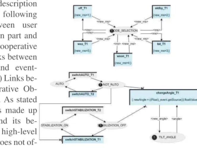
Fig. 4: High-level Petri net model describing the be-haviour of the page WXR
Figure 4 shows the entire behaviour of page WXR which is made of two non con-nected parts: (1) The Petri net in the upper part handles events received from the 5 CheckButtons (see left-hand side of Fig. 2 for the presentation part). Even though they
are CheckButtons the actual behaviour of that application makes it only possible to se-lect one of them at a time. The current sese-lection (an integer value from 1 to 5) is carried by the token stored in MODE_SELECTION place and corresponds to one the possible CheckButtons (OFF, STDBY, TST, WXON, WXA). The token is modified by the tran-sitions (new_ms = 3 for instance) using variables on the incoming and outgoing arcs as formal parameters of the transitions. (2) The Petri net in the lower part handles events from the 2 PicturePushButton and the EditBoxNumeric. Interacting with these buttons will change the state of the application. In the current state, this part of the application is in the manual state and the tokens are placed in the NOT_AUTO and STABILIZA-TION_OFF. This configuration of tokens is required to make available of the edit box to the user (visible on the model as transition changeAngle_T1 is in a darker colour). Activation Function. For WIMP interfaces user towards system interaction (inputs) only takes place through widgets. Each user action on a widget may trigger one of the CO event handlers. The relationship between user services and widgets is fully stated by the activation function that associates each event from the presentation part to the event handler to be triggered and to the corresponding rendering method for representing the activation or the deactivation: When a user event is triggered, the Activation function is notified (via an event mechanism) and requires the CO to fire the corresponding event handler providing the value from the user event. When the state of an event handler changes (i.e. becomes available or unavailable), the Activation function is notified (via the observer and event mechanism presented above) and calls the corresponding acti-vation rendering method from the presentation part with values coming from the event handler.
The activation function is fully expressed through a mapping to a CO behaviour element. Figure 5 shows the activation function for page WXR. Each line in this ta-ble describes the three objects taking part in the activation
process. Fig. 5: Activation Function of the page WXR The first line, for instance, describes the relationship between the user event ask_-off (produced by clicking on the CheckButton OFF), the event handler ask_-off (from the behaviour) and the activation rendering method setWXRModeSelectEnabled from the presentation part. More precisely: (i) When the event handler off becomes enabled, the activation function calls the activation rendering method setWXRModeSelectEnabled providing it with data about the enabling of the event handler. On the physical inter-action side, this method call leads to the activation of the corresponding widget (i.e. presenting the checkButton OFF as available). (ii) When the button OFF of the presen-tation part is pressed, the presenpresen-tation part raises the event called asked_off. This event is received by the activation function which requires the behaviour part to fire the event handler off (i.e. the transition off_T1 in the Petri net of Figure 4).
Rendering function. For WIMP interfaces system towards user interaction (outputs) present to the user the state changes that occurs in the system. The rendering function maintains the consistency between the internal state of the system and its external
ap-pearance by reflecting system states changes on the user interface. Indeed, when the state of the Cooperative Object changes (e.g. marking changes for a given place), the Rendering function is notified (via the observer and event mechanism) and calls the corresponding rendering method from the presentation part with tokens or firing values as parameters. In a similar way as for the Activation function, the Rendering function is fully expressed as a CO class.
The rendering function of the WXR application is presented in Fig. 6. In this table one line describes the three objects taking part in the rendering process. The first line for instance describes the relationship between the place MODE_SELECTION, the event linked to this place (and in which we are interested in token_enter) and the rendering method showModeSelection from the presentation part component.
The signification of this line is: When a token enters the place MODE_SELEC-TION, the rendering function is notified and calls the rendering method showMod-eSelection providing it with data concern-ing the new markconcern-ing of the place that is used as parameters of the rendering
method. Fig. 6: Rendering Function of the page WXR
8
Assessment
To the best of our knowledge, there is currently no full fledge development framework for covering every aspect of modelling and designing related to interactive systems. Our work project targets such a framework for interactive systems complying with ARINC 661 standard. This is the first integrated formalised framework for formal development of HMI. To support the proposed framework, we have developed a pivot modelling language, FLUID, to specify HMI requirements. Since a long time, stepwise refinement plays an important role for modelling complex systems. We also target a correct by construction design of interactive systems abstractly and then progressively develop a concrete model closed to an implementation. This progressive development allows us to introduce functional behaviour and safety properties related to system and user interactions.
The proposed language is expressive enough to cover possible functional behaviour, system input and output states, presentation, and nominal and non-nominal scenar-ios. The FLUID language allows us to build a complex HMI systematically, including reasoning for each step systematically considering functions, properties and domain knowledge related to HMI. To demonstrate the practicality of the proposed language, we have developed industrial examples. We have already developed the HMIs for Auto-matic Cruise Control (ACC), Traffic alert and Collision Avoidance System (TCAS) and MPIA. We can provide a list of safety properties, and nominal and non-nominal scenar-ios to check the correctness of a formalized system including interaction behaviour. The properties and scenarios derive from the usability principles, such as usability, flexibil-ity and robustness. The presented case study covers only some of the usabilflexibil-ity princi-ples. such as consistency, observability, tagging and task conformance. In addition, the
ICO specification fully describe the potential interactions that users may have with the application to validate the dynamic behaviour, visual properties and task analysis.
Modelling an interactive system using the FLUID language provides a common understanding for the various stakeholders. In summary, the FLUID model is an abstract pivot core model of HMI for expressing interaction behaviour using state transition systems, assumptions, properties and scenarios. If there will be any error detected then the FLUID model can be modified accordingly. Many techniques, like Event-B, ProB, ICO, task analysis with CTT have been applied on FLUID model. This modelling and analysing steps can be applied iteratively to obtain a correct FLUID model. Similar to this framework, in our MPIA case study, we use on the Event-B modelling language for specifying system and defining safety properties while we use ICO for analysing possible interactions by refining the FLUID model. Note that the use of different tools provides us more confidence on the defined FLUID model. On the other hand we need to check the combination of the approach for an interactive system and the freedom of the integration of different techniques and tools.
9
Related Work
Several approaches are developed in the past years for modelling, designing, verifying and implementing interactive systems. Due to increasing complexity, formal methods is considered as a first-class citizen for modelling and designing the interaction behaviour of HMI for critical systems. There are several approaches, such as Petri net, process algebra and model checking, have been used successfully for checking the intended behaviour of HMI. Palanque et al. [25, 26] propose the development of HMI using In-teractive Cooperative Objects (ICO) formalism, in which the object-oriented framework and possible functional behaviour are described with high-level Petri-nets.
Compos et al. [11] propose a framework for checking the HMI system for a given set of generic properties using model checkers. Navarre et al. [24] propose a framework for analyzing the interactive systems, particularly for the combined behaviour of user task models and system models to check whether a user task is supported by the system model. Bolton et al. [10] propose a framework to analyze human errors and system failures by integrating the task models and erroneous human behaviour.
In [5], the authors propose an incremental development of an interactive system us-ing B methods to model the important properties of HMI, such as reachability, observ-ability and reliobserv-ability. A development lifecycle for generating source code for HMI from an abstract model is presented in [3]. The Event-B language is used for developing the multi-model interactive system supporting with CARE properties using correct by con-struction approach in [4]. In [19], the authors propose an approach with supported tools based on CAV architecture, hybrid model of MVC and PAC, for developing HMI from specification to implementation. In [16], the authors present a developed methodology, based on MVC architecture, for developing an HMI using a correct by construction approach for introducing functional behaviour, safety properties and HMI components. A formal interaction mechanism is described using the synchronous data flow lan-guage Lustre [17] at ONERA. In [7], the authors present derivation of possible interac-tions from an informal description of the interactive system. These derived interacinterac-tions
are used to model a formal model of the interactive system for checking and validating the required HMI behaviour of interactive system, and for generating the test cases [8]. A modelling language, LIDL (LIDL Interaction Description Language), is proposed in [20] to describe a formal description of possible interaction of HMI. In this language, the static nature of HMI is specified using interfaces and the dynamic nature of HMI is specified as interactions. The semantics of this language is based on synchronous data flows similar to Lustre that makes the process easy for formal verification and code gen-eration. In [15], the authors propose a formal development process for designing HMI for safety-critical systems using LIDL and S3 solver.
The project CHI+MED [13] proposes modelling in Modal Action Logic (MAL) and proofs in PVS for developing HMI of medical systems. In [18], the authors present a methodology to design a user interface compliant with use-related safety requirements using formal methods. In [12], the authors propose an approach for checking the re-quired properties of executable models of interactive software in djnn framework. The
djnnframework describes interactive components in hierarchical manner, including the low level details such as graphics, behaviours, computations and data manipulations.
All the above approaches are all confronted with different issues like the lack of abstraction or of formal design patterns for handling different aspects of interactive sys-tems. Nevertheless, the main contribution of these researches and studies is to demon-strate only parts of the interactive systems such as interaction, task analysis etc. To our knowledge there is no work related to modelling, refinement, domain knowledge integration and management, scenarios, task analysis together for developing interac-tive systems. Our work is the first integrated framework for modelling and designing interactive systems by defining different components of interactive systems. Note that our defined language FLUID is able to model interaction behaviour, domain properties, scenarios and tasks properties for interactive systems using a correct by construction. To specify everything in one language provides a common understanding to the various stockholders.
10
Conclusion
This paper presents a formal approach for developing Human Machine Interface com-plying with ARINC 661. This development approach is centered around the pivot mod-elling language, FLUID, which is proposed in our FORMEDICIS project for specifying HMI requirements. A FLUID model consists of states, assumptions, expectations, nom-inal and non nomnom-inal properties, and scenarios. A formal model can be derived from a FLUID model for reasoning and analyzing an interactive behaviour of a system under the given safety properties. In our work, we have used the Event-B modelling language for producing a formal model and PetShop CASE tool for producing ICO model. We have used MPIA case study for developing a FLUID model. Further, the FLUID model is used for producing Event-B model and ICO model. The Event-B model is used to check interaction behaviour considering domain properties, including safety properties, and the ICO model is used for validating visual properties and in task analysis. More-over, we have also used the ProB model checker tool to analyze and to validate the developed MPIA model. The formalization and the associated proofs presented in this
work can be easily extended to other formal methods and model checkers that can be used for modelling interactive systems.
As future work, our objective is to define a refinement relationship for FLUID mod-els to get closer to an implementation. Such refinement allows us to perform formal verification at the code level and we do not need to add any other verification approach. Another future work is to automate the model generation process from a FLUID model, so that a formal model can be produced and verified in any target modelling language. Acknowledgment. This study was undertaken as part of the FORMEDICIS (FOR-mal MEthods for the Development and the engineering of Critical Interactive Systems) ANR-16-CE25-0007.
References
1. Abrial, J.R.: Modeling in Event-B: System and Software Engineering. Cambridge University Press, New York, NY, USA, 1st edn. (2010)
2. Abrial, J.R., Butler, M., Hallerstede, S., Hoang, T.S., Mehta, F., Voisin, L.: Rodin: An open toolset for modelling and reasoning in event-b. Int. J. Softw. Tools Technol. Transf. 12(6), 447–466 (Nov 2010)
3. Aït-Ameur, Y.: Cooperation of formal methods in an engineering based software develop-ment process. In: Integrated Formal Methods, Second International Conference, IFM 2000, Dagstuhl Castle, Germany, November 1-3, 2000, Proceedings. pp. 136–155 (2000) 4. Ait-Ameur, Y., Ait-Sadoune, I., Baron, M.: Etude et comparaison de scénarios de
développe-ments formels d’interfaces multi-modales fondés sur la preuve et le raffinement. In: RSTI-Ingénierie des Systèmes d’Informations 13(2). pp. 127–155 (2008)
5. Aït-Ameur, Y., Girard, P., Jambon, F.: Using the B formal approach for incremental spec-ification design of interactiv systems. In: Engineering for Human-Computer Interaction, IFIP TC2/TC13 WG2.7/WG13.4 Seventh Working Conference on Engineering for Human-Computer Interaction, September 14-18„ Heraklion, Crete, Greece. pp. 91–109 (1998) 6. ARINC 661-2: Prepared by Airlines Electronic Engineering Committee. Cockpit Display
System Interfaces to User Systems. Arinc Specification 661-2 (2005)
7. Ausbourg (d’), B., Durrieu, G., Roché, P.: Deriving a formal model of an interactive system from its UIL description in order to verify and to test its behaviour. In: Proceedings of the Eurographics Workshop DSV-IS’96. Namur, Belgium (June 1996)
8. Ausbourg(d’), B.: Using Model Checking for the Automatic Validation of User Interfaces Systems. In: Markopoulos, P., Johnson, P. (eds.) Design, Specification and Verification of Interactive Systems ’98. Eurographics, Springer (June 1998)
9. Barboni, E., Martinie, C., Navarre, D., Palanque, P.A., Winckler, M.: Bridging the gap be-tween a behavioural formal description technique and a user interface description language: Enhancing ICO with a graphical user interface markup language. SCP 86, 3–29 (2014) 10. Bolton, M.L., Siminiceanu, R.I., Bass, E.J.: A systematic approach to model checking human
- automation interaction using task analytic models. IEEE Transactions on Systems, Man, and Cybernetics - Part A: Systems and Humans 41(5), 961–976 (2011)
11. Campos, J.C., Harrison, M.D.: Systematic Analysis of Control Panel Interfaces Using Formal Tools, pp. 72–85. Springer Berlin Heidelberg, Berlin, Heidelberg (2008)
12. Chatty, S., Magnaudet, M., Prun, D.: Verification of properties of interactive components from their executable code. In: Proceedings of the 7th ACM SIGCHI Symposium on Engi-neering Interactive Computing Systems. pp. 276–285. EICS’15, ACM, NY, USA (2015)
13. Curzon, P., Masci, P., Oladimeji, P., Rukš˙enas, R., Thimbleby, H., D’Urso, E.: Human-Computer Interaction and the Formal Certification and Assurance of Medical Devices: The CHI+MED Project. In: 2nd Workshop on Verification and Assurance (Verisure2014), in as-sociation with Computer-Aided Verification (CAV), Vienna Summer of Logic (2014) 14. FORMEDICIS Project. https://anr.fr/Projet-ANR-16-CE25-0007
15. Ge, N., Dieumegard, A., Jenn, E., d’Ausbourg, B., Aït-Ameur, Y.: Formal development pro-cess of safety-critical embedded human machine interface systems. In: 11th International Symposium on Theoretical Aspects of Software Engineering, TASE’17. pp. 1–8 (2017) 16. Geniet, R., Singh, N.K.: Refinement based formal development of human-machine interface.
In: Software Technologies: Applications and Foundations - STAF 2018 Collocated Work-shops, Toulouse, France, June 25-29, 2018, Revised Selected Papers. pp. 240–256 (2018) 17. Halbwachs, N., Caspi, P., Raymond, P., Pilaud, D.: The synchronous dataflow programming
language Lustre. In: Proceedings of IEEE. pp. 1305–1320. No. 9 in 79 (September 1991) 18. Harrison, M.D., Masci, P., Campos, J.C., Curzon, P.: Verification of user interface software:
The example of use-related safety requirements and programmable medical devices. IEEE Trans. Human-Machine Systems 47(6), 834–846 (2017)
19. Jambon, F.: From formal specifications to secure implementations. In: Computer-Aided De-sign of User Interfaces III, Proceedings of the Fourth International Conference on Computer-Aided Design of User Interfaces, May, 15-17, 2002, Valenciennes, France. pp. 51–62 (2002) 20. Lecrubier, V.: A formal language for designing, specifying and verifying critical embed-ded human machine interfaces. Theses, INSTITUT SUPERIEUR DE L’AERONAUTIQUE ET DE L’ESPACE (ISAE) ; UNIVERSITE DE TOULOUSE (Jun 2016), https://hal. archives-ouvertes.fr/tel-01455466
21. Leuschel, M., Butler, M.: ProB: A Model Checker for B, pp. 855–874. LNCS, Springer (2003)
22. Myers, B.A.: Why are human-computer interfaces difficult to design and implement? Tech. rep., Carnegie Mellon University, Pittsburgh, PA, USA (1993)
23. Navarre, D., Bastide, R., Palanque, P.: A tool-supported design framework for safety critical interactive systems. Interacting with Computers 15(3), 309–328 (2003)
24. Navarre, D., Palanque, P.A., Paternò, F., Santoro, C., Bastide, R.: A tool suite for integrating task and system models through scenarios. In: 8th International Workshop on Interactive Systems: Design, Specification, and Verification (DSV-IS). pp. 88–113 (2001)
25. Palanque, P., Bastide, R., Sengès, V.: Validating interactive system design through the verifi-cation of formal task and system models, pp. 189–212. Springer US, Boston, MA (1996) 26. Palanque, P.A., Bastide, R.: Petri net based design of user-driven interfaces using the
interac-tive cooperainterac-tive objects formalism. In: Design, Specification and Verification of Interacinterac-tive Systems, Proc. of the First International Eurographics Workshop, Italy. pp. 383–400 (1994) 27. Palanque, P.A., Ladry, J., Navarre, D., Barboni, E.: High-fidelity prototyping of interactive
systems can be formal too. In: Human-Computer Interaction. New Trends, 13th International Conference, HCI International 2009, San Diego, CA, USA, Part I. pp. 667–676 (2009) 28. Paterno, F., Mancini, C., Meniconi, S.: ConcurTaskTrees: A Diagrammatic Notation for
Specifying Task Models, pp. 362–369. Springer US, Boston, MA (1997)
29. Shneiderman, B., Plaisant, C., Cohen, M., Jacobs, S., Elmqvist, N.: Designing the User In-terface - Strategies for Effective Human-Computer Interaction, 6th Edition. Pearson (2016)