HAL Id: hal-02904522
https://hal.archives-ouvertes.fr/hal-02904522
Submitted on 22 Jul 2020
HAL is a multi-disciplinary open access
archive for the deposit and dissemination of sci-entific research documents, whether they are pub-lished or not. The documents may come from teaching and research institutions in France or abroad, or from public or private research centers.
L’archive ouverte pluridisciplinaire HAL, est destinée au dépôt et à la diffusion de documents scientifiques de niveau recherche, publiés ou non, émanant des établissements d’enseignement et de recherche français ou étrangers, des laboratoires publics ou privés.
Bases and experimental validation of a novel VSPIN
model: towards functional spin-controlled VCSELs
Mehdi Alouini, Julien Frougier, Alexandre Joly, Ghaya Baili, Daniel Dolfi,
Jean-Marie George
To cite this version:
Mehdi Alouini, Julien Frougier, Alexandre Joly, Ghaya Baili, Daniel Dolfi, et al.. Bases and experi-mental validation of a novel VSPIN model: towards functional spin-controlled VCSELs. SPIE Pho-tonics West - OPTO 2018, Jan 2018, San Francisco, United States. pp.105401S, �10.1117/12.2289694�. �hal-02904522�
PROCEEDINGS OF SPIE
SPIEDigitalLibrary.org/conference-proceedings-of-spie
Bases and experimental validation of
a novel VSPIN model: towards
functional spin-controlled VCSELs
Alouini, M., Frougier, J., Joly, A., Baili, G., Dolfi, D., et al.
M. Alouini, J. Frougier, A. Joly, G. Baili, D. Dolfi, J. M. George, "Bases and
experimental validation of a novel VSPIN model: towards functional
spin-controlled VCSELs," Proc. SPIE 10540, Quantum Sensing and Nano
Electronics and Photonics XV, 105401S (26 January 2018); doi:
10.1117/12.2289694
Event: SPIE OPTO, 2018, San Francisco, California, United States
Bases and experimental validation of the VSPIN model : towards
functional spin-controlled VCSELs (Invited)
M. Alouini*
a,b, J. Frougier
c, A. Joly
b, G. Baili
b, D. Dolfi
b, and J.M. George
ca
Institut FOTON, Université de Rennes 1, CNRS, Campus de Beaulieu, 35042 Rennes, France
b
Thales Research & Technology, 1 av. Augustin Fresnel, 91767 Palaiseau Cedex, France
c
Unité Mixte de Physique CNRS-Thales, 1 av. Augustin Fresnel, 91767 Palaiseau, France
ABSTRACT
Optimization of spin-lasers relies on the proper design of the active medium but also on a thorough understanding of the vectorial dynamics of the electromagnetic field in the laser cavity itself. A vectorial approach based the Jones formalism associated to the resonant condition of the field in the laser cavity is derived in order to draw the main guidelines for developing functional spin-controlled VCSELs. This general modelling framework, which accounts for spin injection effects as a gain circular dichroism in the active medium, shows that any residual phase anisotropy in the laser has a detrimental role on polarization switching. The same framework, is used to propose two solutions enabling to overcome this drawback: either by compensating the phase anisotropy or by preparing the laser cavity so that its eigenstates are circularly polarized. Moreover, unlike in spin-LED, we show that the leverage effect existing in the laser due to eigenmodes coupling makes it possible to switch the laser from a polarized oscillation to the orthogonal one despite the weak spin injection efficiency due to spin decoherence. All these predictions are confirmed using external cavity VCSELs which offer an ideal playing field for experimental investigations. Based on these developments, future trends towards the achievement of efficient and compact spin-lasers will be given.
Keywords: Laser, Spin-laser, Polarization
1. INTRODUCTION
In the past decade, a continuous interest and a research effort have been dedicated to the study of spin-injection into Semiconductor based Light Emitting Device such as Light Emitting Diodes (LEDs) and more recently Spin-Lasers such as Vertical Cavity Surface Emitting lasers (VCSELs) [1,2]. In these devices, quantum selection rules associated with the angular momentum make it possible to convert electronic spin information into photon polarization information [3]. State of the art spin-LEDs are shown to provide good conversion efficiency leading to a degree of circular polarization (DoCP) as high as 90 % at 1.5 K and with a 3 T external magnetic field [1]. Spin-lasers are also expected to exhibit better performances in terms of DoCP due to the presence of an optical cavity imposing a resonant condition to the electro-magnetic field, including its polarization [4-7]. In comparison to SC edge-emitting lasers, where the polarization state is mainly defined by the optical waveguide, Vertical-Cavity Surface Emitting Lasers (VCSELs) appear to be good candidates for a spin-laser [8-13]. As compared to spin-unpolarized lasers, spin lasers offer interesting properties such as improvement of modulation bandwidth, threshold reduction, new modulation format by coding the light polarization state, and better eye diagram [8,9]. Therefore, spin injected lasers, operating at RT without external magnetic field, could be one of the future technological breaking devices in the telecommunication domain. Nevertheless, it is shown that excessive residual linear anisotropies can fix the polarization eigenstates to linear polarizations [14-17], preventing any visible effect of spin injection especially when the spin coherence is barely maintained. Several models based on rate equations and including spin dependent carrier dynamics have already been developed for VCSELs in order to describe the evolution of the laser polarization with different degrees of accuracy [18-20]. However, these models mainly consider carriers’ dynamics in the active medium taking into account microscopic parameters or assume that the laser polarization state is similar to that given by the gain structure.
*[email protected]; phone +33 223 236 658; http://foton.cnrs.fr
Keynote Paper
Quantum Sensing and Nano Electronics and Photonics XV, edited by Manijeh Razeghi, Gail J. Brown, Jay S. Lewis, Giuseppe Leo, Proc. of SPIE Vol. 10540, 105401S · © 2018 SPIE
CCC code: 0277-786X/18/$18 · doi: 10.1117/12.2289694 Proc. of SPIE Vol. 10540 105401S-1
Downloaded From: https://www.spiedigitallibrary.org/conference-proceedings-of-spie on 22 Jul 2020 Terms of Use: https://www.spiedigitallibrary.org/terms-of-use
The use of an external laser cavity such as for Vertical external-Cavity Surface emitting Lasers (VeCSELs) enables the insertion of additional optical components inside the laser cavity to possibly reveal the effect of spin injection on the laser polarization. For instance, we have shown that preparing the laser cavity so that its two possible polarization eigenstates correspond to left and right circular polarizations is the optimal architecture for stimulating a full polarization switch even with very poor spin injection efficiency [21]. Nevertheless, the need for an intra-cavity Faraday rotator to compensate the residual anisotropy of the semiconductor structure makes this approach cumbersome and difficult to implement for a realistic marketable device. More recently, we have shown that compensating the linear phase anisotropy in the cavity is another way to stimulate polarization switching through spin injection, but is less efficient [22]. These experimental developments have been guided by a simple and pragmatic modelling approach taking into account the presence of additional optical components inside the laser cavity and considering that spin injection phenomenologically leads to a tiny gain circular dichroism in the active medium. We describe here this modeling approach that enabled us to successfully predict the polarization behavior of spin-lasers and to draw the general guidelines for developing lasers sensitive to even very low efficient spin injection. The Vectorial-SPIN (VSPIN) model presented here relies on the derivation of the field resonant condition in the framework of the Jones formalism.
2. VSPIN : GENERAL FRAMEWORK FOR MODELLING SPIN LASERS
The Jones formalism [[23]3] offers an ideal framework for determining the polarization state of a laser. Indeed, in the steady state, the resonance condition imposed by the laser cavity makes the field coherent by definition leading to a well-defined state of polarization [[24]4]. The determination of the laser characteristics, i.e. longitudinal and transverse distributions of the field as well as the associated gain and frequency, can thus be performed by solving the resonant condition for a 2×2 Jones matrix which takes into account all the elements inside the cavity including the active medium [[25]5].
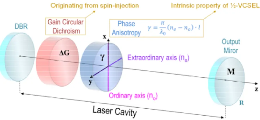
Figure 1. Schematic representation of the laser cavity.
In any laser, the cold cavity exhibits always a residual linear anisotropy of phase [[15]5], which defines the two polarization eigenstates of the cavity. One assumes that this phase anisotropy comes from the active medium and can be represented by a thin birefringent layer, as sketched in Fig.1. The associated Jones matrix is [[26],[27]7]
= 0
0 , (1)
where γ denotes this phase anisotropy, λ0 is the mean laser wavelength, and l is the optical length of the cavity. =
is the mean refractive index of the birefringent element, where no and ne are the ordinary and extraordinary indices
of the birefringence, respectively. Accordingly, the phase anisotropy reads
= ( − ) . (2)
Under these conditions, the cold cavity exhibits two eigenstates, which are linearly polarized along the ordinary and extraordinary axes of the residual birefringence. The next step is to determine to what extent a circular dichroism of gain, induced by preferential spin injection can modify these eigenstates and lead to circularly polarized eigenstates, as already
Proc. of SPIE Vol. 10540 105401S-2
Downloaded From: https://www.spiedigitallibrary.org/conference-proceedings-of-spie on 22 Jul 2020 Terms of Use: https://www.spiedigitallibrary.org/terms-of-use
observed in the literature for spin lasers [[28]8]. This dichroism can be either measured experimentally or predicted theoretically for a given active medium taking into account light/matter interaction within the actual multilayer structure [29]. We define the circular dichroism of gain as Δ = − . The associated Jones matrix reads:
= ̅ − Δ
Δ ̅ . (3)
In this matrix, ̅ = represents the active medium mean gain, where GR et GL are the gains seen by right hand and
left hand circular polarized fields, respectively. The matrix does not bring any phase anisotropy γ as long as circular polarizations are considered, right or left handed. However, it induces a phase term when the incident polarization is linear leading to an elliptical output polarization, whose ellipticity increases with the gain circular dichroism. In other words, the gain circular dichroism Δ induces the projection of a linear polarization field onto the orthogonal state. We now assume that the cavity input mirror is perfectly reflecting and isotropic such that its presence can be omitted in this vectorial formalism. Note that this hypothesis is not restrictive, since any residual birefringence in the mirror could be easily taken into account in our vectorial formalism. Finally, assuming that the output coupler is isotropic and that its reflectivity is R, the associated Jones matrix reads:
= √ 1 0
0 1 . (4)
Let us now consider that the axes of the residual birefringence are oriented along x and y, z being the propagation axis (see Fig.1). The total Jones matrix at the output mirror after one round trip of the cavity is
= . . . . (5)
Note that, in this expression, the Jones matrix associated to the gain takes into account the back and forth interaction of the field with the gain structure while ejφ is the cumulative phase after one roundtrip propagation through the cavity.
Developing Eq. 5 yields
= √ ̅ ( . . ) − Δ
Δ , (6)
where = is the electromagnetic field wave number, nma and ema are the refractive index and the thickness of the
active medium. L is the cavity length excluding the active medium and the birefringent plate. In the case of a monolithic VCSEL, L = 0. Finally, Δ = holds for the normalized circular dichroism of gain. For the sake of conciseness, we define the effective length, = . + . + , representing the mean optical length of the cavity. The resonance condition of the field
E
r
for one round trip in the cavity imposes that= . (7)
In this expression, λ are the eigenvalues
.
The system considered here having two degrees of freedom, two eigenvalues are possible.
The diagonalization of the matrix enables to find out the two complex eigenvalues which contain both the frequency and the gain of each mode. The associated eigenvectors describe the two possible polarization states. The characteristic polynomial obtained by solving Eq. 7 is:( − cos( )) = Δ ² − sin ²( ). (8) The laser behavior is ruled by this equation, so different oscillation regimes will appear depending on the relative ratio
between the linear anisotropy of phase γ and the circular dichroism of the gain ΔGN. Furthermore, the saturated gains and
the laser oscillation frequencies in the eigenbasis are connected to the eigenvalues through
=√ ̅ . (9)
In order to simplify the problem, we assume in the following that ΔG and γ are both positive values. Accounting for this condition and according to the characteristic polynomial of Eq. 8, three cases must be considered.
Proc. of SPIE Vol. 10540 105401S-3
Downloaded From: https://www.spiedigitallibrary.org/conference-proceedings-of-spie on 22 Jul 2020 Terms of Use: https://www.spiedigitallibrary.org/terms-of-use
2.1 Linear birefringence overpowers the effective spin injection in the active medium ∆ ² < 4 ²( ): In this case, the eigenvalues λ± have complex values:
±= ( ) ± ( ) − Δ . (14)
The imaginary part of the eigenvalues lifts the frequency degeneracy so that each eigenstate now has its own oscillation frequency. By developing Eq. 8, one finds that the frequency difference reads
Δ = − = arctan tan( ) . 1 − ( ) ² . (15)
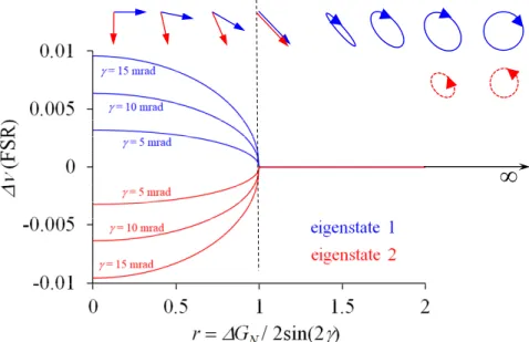
The evolution of the frequency difference as a function of r is plotted in Fig.2, where r refers to the ratio Δ ⁄2 sin( ). For a given phase anisotropy, the frequency difference decreases as the gain circular dichroism increases. More precisely, Δ remains almost constant for low to moderate values of ΔGN , i.e. Δ < sin( )/10, and drops abruptly
when ΔGN approaches 2sin ( ). This behavior leads to frequency locking when Δ = 2. sin ( ), which translates to r = 1.
We now investigate how the laser polarization state evolves with respect to the gain circular dichroism ΔGN. The two
allowed polarization states correspond to the eigenvectors of the laser Jones matrix . Taking into account the eigenvalue expression of Eq. 14, the x and y components of the electric field satisfy the relation
= − 1 ± √1 − (16)
The two eigenstates are thus two linear polarizations whose orientations depend on the ratio between the gain circular dichroism and the linear birefringence. Consequently, if both modes are emitting, the polarization of the total light field is time-dependent due to the time-dependent phase difference. The polarization rotates around the Poincaré sphere at a rate corresponding to the frequency difference [30]. It is worth highlighting that the presence of gain circular dichroism breaks the orthogonality between the two polarizations. For a fixed linear birefringence, as ΔGN increases, the two
polarizations progressively align along a common direction at ±45° with respect to the crossed initial orientations until they become perfectly aligned for = 1. In this unique situation the two eigenstates become degenerate in terms of polarization and frequency.
2.2 Effective spin-polarization in the active medium compensates the linear birefringence ∆ ² = ²( ): This is the unique situation mentioned above. In this case the characteristic polynomial given by Eq. 8 has a single solution ±= ( )and the electromagnetic field satisfies = −1
.
The eigenstates are two indistinguishable linearpolarizations that are collinear with degenerate frequencies. Consequently, the laser beam consists of one polarization oriented at -45° with respect to the neutral birefringence. Hence, the continuity between cases 2.1 and 2.2 is well verified.
2.3 Effective spin-polarization in the active medium overpowers the linear birefringence ∆ ² > 4 ²( ) In this case, the characteristic polynomial has two solutions which are this time both real
±= ( ) ± Δ − ( ) (17)
Consequently, the two eigenpolarizations exhibit degenerate frequencies. In practice, the laser output polarization is unique and results from the linear superposition of the two eigenstates. The output polarization state evolves as a function of the pump rate and the amount of gain dichroism since the possible oscillation of the eigenstates is directly ruled by the gain dichroism itself (oscillation condition). The x and y components of the electrical field satisfy the relation:
= ± (18)
whose resolution in polar coordinate gives for the module
Proc. of SPIE Vol. 10540 105401S-4
Downloaded From: https://www.spiedigitallibrary.org/conference-proceedings-of-spie on 22 Jul 2020 Terms of Use: https://www.spiedigitallibrary.org/terms-of-use
= 1 (19) and for the phase
Φ±= = ∓ arctan( ² − 1) (20)
Thus the two possible eigenstates exhibit elliptical polarization, as shown in Fig.2. When the gain circular dichroism becomes very large compared the phase anisotropy (which also implies that the phase anisotropy is negligible), the two eigenstates lead to a single perfectly circularly-polarized state as lim → Φ±= ± . Besides, the characteristic
polynomial provides the gain seen by each eigenstate:
±= √ cos( ) ± sin( ) ² − 1 (21)
In practice, the eigenstate experiencing the highest gain prevails. In our case, the eigenstate labeled 1 in Error!
Reference source not found.Fig. 2 will preferentially oscillate. As previously mentioned, if the nonlinear coupling
constant C between the two eigenstates is lower than 1, the eigenstate labeled 2 will reach the oscillating regime for a pumping rate superior to that of eigenstate 1. The appearance of this second eigenstate will lead to a diminution of the circular polarization degree. In other words, since the eigenfrequencies are degenerate, the output beam of the laser exhibits a unique polarization state formed by the linear superposition of the two possible eigenpolarizations. If C >1, then only the first eigenstate oscillates and the simultaneous oscillation of both eigenstates in the cavity is forbidden for any given pumping power. In this case, the circular polarization degree increases indefinitely with the pumping power.
2.4 Summary
Figure 2 : Evolution of the frequency splitting and the two eigenpolarizations as a function of the ratio r between the circular
dichroism of gain ΔGN and the linear birefringence of phase γ.
Fig.2 summarizes the previous results regarding the vectorial behavior of a laser including a circular dichroism of gain in the active medium and residual linear birefringence in the cavity. Regardless of its magnitude, the linear birefringence is always present in a laser due to residual constraints in the active medium or/and in the optical components inside the laser cavity. In this framework, the VSPIN model shows that when there is no gain circular dichroism in the active medium the laser eigenstates correspond to two orthogonal linear polarizations with a frequency difference proportional to the linear birefringence. As the gain circular dichroism increases, the two eigenstates lose their orthogonality and the two linear polarizations progressively rotate and align along a common direction while the eigenfrequencies remain almost constant. When the gain circular dichroism is sufficiently high, the two linear polarizations become superposed
∞
Proc. of SPIE Vol. 10540 105401S-5
Downloaded From: https://www.spiedigitallibrary.org/conference-proceedings-of-spie on 22 Jul 2020 Terms of Use: https://www.spiedigitallibrary.org/terms-of-use
and the associated eigenstates become degenerate due to phase locking. In this unique situation the laser emits a single polarization oriented at 45° with respect to the neutral axes of the linear birefringence. When the gain circular dichroism increases further, the polarization states evolve from linear to elliptical with the long axis oriented at 45°. This ellipticity degree decreases as the gain circular dichroism keeps increasing until the polarization states become circular. Note that, in the region where the polarization states are elliptical, the eigenstate 2 with an elliptical polarization orthogonal to the eigenstate 1 can oscillate if the nonlinear coupling constant C (ruled by the cross gain saturation) is lower than 1. In this case, the eigenstate experiencing the less gain will start oscillating after the dominant eigenstate when the pump power is increased. It is consequently possible to observe a decrease of the degree of circular polarization when the laser is operated far above threshold. This behavior predicted by the VSPIN model can explains the observations of Iba et al. in [28].
3. EXPERIMENTAL VALIDATION AND IMPROVEMENT OF SPIN INJECTION EFFECT ON POLARIZATION SWITCHING
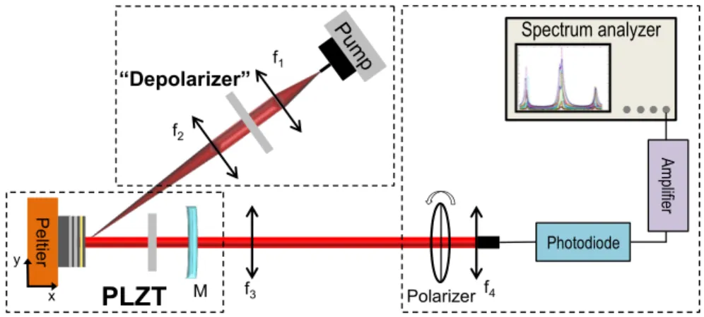
By considering the theoretical results above, circular polarization can be obtained only if the ratio r between the circular gain dichroism and the linear phase birefringence is much higher than one. In VCSELs, the effective circular gain dichroism induced by spin injection being extremely low, the linear phase birefringence has to be reduced so that the effect of spin injection on the laser polarization is revealed. Up to now, the circular gain dichroism is limited to few percent due to the short spin lifetime at room temperature in Semiconductor structures (60 ps [31] compared to carrier lifetime in the order of 2 ns [32]). Although low, the residual linear phase anisotropy is still equal to several tens of mrad [17], leading to a ratio r around 0.25. This confirms the need to compensate the residual linear phase anisotropy in order to isolate spin effects in these lasers and in particular to obtain controlled circular polarizations. The experimental setup is depicted in Figure 4. The ½ VCSEL gain chip, operating at 1.5 µm, is designed and fabricated by the École Polytechnique Fédérale de Lausanne (EPFL).
Figure 4: Experimental setup and characterization setup of the VECSEL for the birefringence compensation. f1 = 11 mm, f2 = 50 mm, f3 =75 mm, f4 = 11 mm, M: (R = 25 mm, T = 0.1 %).
As an alternative to an efficient electrical spin-injector, the so called “optical orientation rules” enable the spin injection in the gain medium through the control of the optical pump polarization. The pump system is composed of a 980 nm pigtailed single mode diode delivering up to 600 mW. A spatial depolarizer is inserted to limit possible contribution of the circular gain dichroism provided by the pump polarization in the ½ VCSEL. This enables dealing only with linear phase anisotropy and so splitting up the two effects (birefringence compensation and spin injection). A concave mirror with a radius of curvature of 25 mm and a reflectivity of 99 % at 1.5 µm is placed at 25 mm of the ½ VCSEL. An uncoated 100 µm thick YAG etalon is added ensuring single mode operation. In order to compensate, with high accuracy, the residual linear phase birefringence, a PLZT (Lead Lanthanum Zirconium Titanate) electro optical ceramic is inserted in the laser cavity. To measure the reduction of the residual linear phase birefringence of the VECSEL, we use the accurate technique proposed recently [17] which consists in probing the heterodyne beating between the amplified
f3 f1 f2 “Depolarizer” M
PLZT
P e ltie r y x Polarizer Spectrum analyzer f4 Photodiode Ampli fierProc. of SPIE Vol. 10540 105401S-6
Downloaded From: https://www.spiedigitallibrary.org/conference-proceedings-of-spie on 22 Jul 2020 Terms of Use: https://www.spiedigitallibrary.org/terms-of-use
spontaneous emission (ASE) in the crossed polarization direction and the lasing mode itself. The beatnote spectrum obtained in the electrical domain enables then to accurately measure the linear phase birefringence.
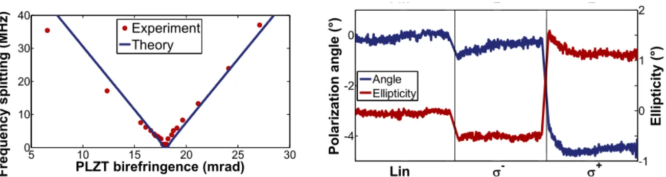
The electric field applied to the PLZT ceramic is oriented so that the induced birefringence balances that of the active medium. By increasing the voltage applied to the PLZT, the frequency splitting, and so the cavity birefringence, decreases. We succeed to decrease the frequency splitting from 40 MHz to less than 1 MHz, so the cavity birefringence from 21 mrad to less than 0.5 mrad: corresponding to a 40 fold reduction. The frequency splitting as a function of the PLZT induced birefringence is plotted in Figure 5. Once the linear phase birefringence is compensated, the pump spatial depolarizer is replaced by a liquid crystal based polarization rotator enabling the pump polarization to be modified from linear to left (σ -) or right (σ +) -handed circular. The linear pump polarization, which corresponds to a balanced spin
injection, is set as the reference. As shown in Figure 5. We observe a rotation of 0.5° and a decrease of the ellipticity of 0.5° for a left handed circular pump polarization, compared to a linear pump polarization. At the opposite, for a right handed circular pump polarization, a rotation of 3.5° and an increase of the ellipticity of 1° are noticed. As expected, the injection of spin down or spin up into the QWs have opposite effects on the ellipticity. This proves the spin injection into the gain medium. However, because of the very low spin injection efficiency, a full polarization switch is still difficult to obtain. More details can be found in [22]. It is important to note that the polarization rotation do not happen at all if the residual linear birefringence is not compensated, as predicted theoretically.
Figure 5: Left: reduction of the residual laser cavity linear birefringence with a voltage controlled PLZT ceramic. Right:
evolution of the laser polarization for three pump polarization states: linear (Lin), right-handed circular polarization (σ+)
and left-handed circular polarization (σ-).
4. TOWARDS A LASER CAVITY OPTIMIZED FOR POLARIZATION SWITCHING BY SPIN INJECTION
4.1 Principle
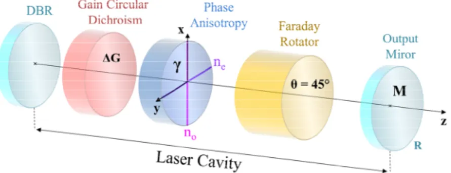
The previous section highlighted that a residual linear birefringence in the laser forces the oscillation of crossed linearly polarized eigenstates. Thus, the laser naturally oscillates with respect to one of these eigenstates or possibly both if the coupling constant in the active medium is low enough. As seen, spin injection generates only a weak circular gain dichroism Δ due to spin decoherence. Additionally, the nonlinear coupling constant being high in semiconductor active media [33], the laser output polarization is expected be linearly polarized with an orientation slightly affected by the spin injection. Consequently, triggering a polarization switch from a given polarization state to the orthogonal polarization state by leveraging a weak effective spin injection will only be possible if the laser cavity has been “prepared” to inherently sustain the oscillation of circularly polarized eigenstates. This configuration can be achieved by inserting a non-reciprocal element such as a Faraday rotator inside the laser cavity [34]. This section addresses the modeling of such a laser cavity illustrated in Fig.6.
5 10 15 20 25 30 0 10 20 30 40 PLZT birefringence (mrad) Fr e q u e nc y s p lit ti ng ( M H z) Experiment Theory 0 5 10 15 20 25 30 -4 -2 0 Pola ri za tion a n gle ( °) Lin σ σ 0 5 10 15 20 25 30-1 0 1 2 E llipt ic it y (°) Angle Ellipticity Lin σ- σ+
Proc. of SPIE Vol. 10540 105401S-7
Downloaded From: https://www.spiedigitallibrary.org/conference-proceedings-of-spie on 22 Jul 2020 Terms of Use: https://www.spiedigitallibrary.org/terms-of-use
Figure 3 : Schematic representation of the cavity including a Faraday rotator.
4.2 Modelling using the VSPIN approach
The Jones matrix associated to the Faraday rotator reads:
= cos ( ) −sin ( )sin ( ) cos ( ) (22)
where θ is the rotation angle of a linearly polarized field crossing the Faraday rotator. This angle is proportional to the Verdet constant, the thickness of the component and the applied magnetic field. The eigenstates of such a matrix are two circular polarizations, right-handed and left-handed irrespective to the value of θ . In practice, θ is adjusted to π/4 in optical isolators such that a linear polarization crossing the element back and forth experiences a rotation of π/2. In the case considered here, is chosen equal to /4 to ensure that the circular birefringence induced by the Faraday rotator dominates any residual linear birefringence in the laser. In this case, the Jones matrix associated with the Faraday rotator simplifies to:
=
√
1 −1
1 1 (23)
It is important to note that this operator couples the linear polarizations. Accounting for the Faraday rotator, the total Jones matrix of the field at the output mirror for one round trip in the cavity becomes:
= . . . (24)
is the Jones matrix of the residual linear birefringence in the active medium given by Eq. 1. is the Jones matrix of the circular gain dichroism induced by spin injection in the active medium given by Eq. 3. Finally, is the Jones matrix of the mirror given by Eq. 4. In the following, we keep the same notations as in the previous section. The normalized gain circular dichroism ΔGN accounts for one round trip in the active medium while ejφ represents the
cumulative phase rotation of the electromagnetic field after one round trip propagation through the laser cavity. The cumulative phase now accounts for the optical path in the Faraday rotator, so that:
Φ = 2 ( . + + . + ) = 2 (25)
where, nF and eF are the mean optical index and the thickness of the Faraday rotator respectively. With this new Jones
matrix, the resonance condition of the field Er for one round trip in the cavity must satisfy =
.
The diagonalization of this Jones matrix leads to two new polarization eigenstates with their associated eigenvalues. In the special case where θ = π/4, the equations greatly simplify leading to the following characteristic polynomial±= (∓2 − Δ ). (26)
As anticipated, the residual phase anisotropy that might exist in the laser or the active medium itself does not play any role in the characteristic polynomial. To highlight a physical insight, one can rewrite the latest equation as follows:
±= (2 ± Δ ). ∓ . (27)
The modulus of this expression gives the gain seen by each polarization eigenstate, that is
±=√ 1 ± Δ , (28)
whereas, its argument provides the two eigenfrequencies of the laser,
Proc. of SPIE Vol. 10540 105401S-8
Downloaded From: https://www.spiedigitallibrary.org/conference-proceedings-of-spie on 22 Jul 2020 Terms of Use: https://www.spiedigitallibrary.org/terms-of-use
30 00 80 60 40 20 -0 0
i
D.a 0.6 D.4 D.2 -0 0 where q is an The frequenc imposed by t eigenstates of components o which proves eigenstates. F induced by th circular dichr switching wil When the res circularly-pol to linear pola insertion of a shown in Fig spectral range Figure 4 : function o 4.3 Summar The insertion for observing to overcome providing nat dichroism ΔG possibility of high enough the frequency the linear bir efficiency is cn integer. Thus
cy difference i the Faraday ro
f the laser can of the field alo
s that the tw Furthermore, he electronic s roism will fav ll be addressed sidual birefrin larized (see F arization at γ = a Faraday rota g.4-right, the f e of the laser c Evolution of t of the linear bire
ry n of a Faraday g full polarizat the detriment tural oscillatio GN induced b f a full polariz (which is the y difference b refringence in considered in s, the frequenc is independent otator and is p n be obtained ong x and y sa ± wo transverse the gain circu spin will have or the oscillat d in the follow ngence is nei
ig.4-left). The = 45°. In prac ator into the l frequency diff cavity indepen the ellipticity (l efringence in th rotator in the tion switching tal contributio ons of the righ by the spin i zation switch case in semic etween the tw n the laser. T the following ±= cy difference b Δ ±= | t of the linear precisely equa by diagonaliz atisfy the expr
±= − . (
components ular dichroism e no influence tion of one eig wing section. ither null nor ey abruptly ch ctice, because laser leads to fference betwe ndent of the li
left) and the fre he active mediu
e VECSEL cav g under low e ons of any res ht- or left- han injection unb provided that conductor acti wo eigenstates The impact o g section. ∓ . , between the tw − | = r phase anisotr al to half the zation of the J ession ) ± . of the field m ΔGN is not e on the laser genstate. The 90°, the two hange to ellipt the linear bire
two possible een these two inear birefring quency differen um. vity enables th effective spin sidual linear b nded circular p balances the g t the nonlinea ive media [33 s is equal to ha of the nonlin wo eigenstate . ropy in the ac free spectral ones matrix. I ( ) + 1, are always in present in th eigenpolariza issue of simul o laser eigens tical polarizati efringence is circularly-po eigenstates r gence value.
nce between the
he preparation injection. Mo birefringence polarizations. gain experien ar coupling co 3]). In addition alf the laser fr ear coupling s is: tive medium. range of the l It can be show n quadrature his expression ations. Howev ltaneity and ef
states are alm ion in the vici small, it is rea olarized eigenp emains consta
e two laser eige
n of the laser i oreover, such in the active Within this fr nced by each onstant C betw n, the vectoria free spectral ra constant on The frequenc laser. Further wn easily that for each of n, so the circu ver, as shown b fficiency of th most perfectly inity of γ = 45 asonable to as polarizations. ant and equal
enstates (right) a in the optimal a rotator offer medium and/ framework, the h eigenstate l
ween the two al VSPIN mod ange regardles the polarizat (29) (30) cy shift is only rmore, the two the transverse
(31) the two laser ular dichroism by Eq. 28, the he polarization
left and righ 5°, and further ssume that the Moreover, as s half the free
as a
l configuration rs a good way /or cold cavity e circular gain eading to the eigenstates is del shows tha ss the value o tion switching y o e r m e n ht r e s e n y y n e s at f g
Proc. of SPIE Vol. 10540 105401S-9
Downloaded From: https://www.spiedigitallibrary.org/conference-proceedings-of-spie on 22 Jul 2020 Terms of Use: https://www.spiedigitallibrary.org/terms-of-use
5. LEVERAGE EFFECT ON POLARIZATION SWITCHING DUE TO THE EIGENSTATES COUPLING IN THE ACTIVE MEDIUM
The laser cavity can be prepared so that a tiny gain circular dichroism induced by spin injection induces a complete polarization switching. We showed that in practice, a laser cavity incorporating a non-reciprocal effect; such as a Faraday rotator, offers a simple way prepare the cavity by concealing the detrimental effect of any residual linear birefringence. Hence, the gain circular dichroism induced by spin injection effectively acts as a gain disequilibrium between the two polarization eigenstates. This disequilibrium, even low, can trigger a fast and complete [[35]5] polarization switch provided that the nonlinear coupling constant between the eigenstates is high enough to achieve the required leverage effect.
In a Class-A laser, the population inversion densities can be adiabatically eliminated. Under this condition, the laser behavior is described by two first order coupled differential equations which rule the temporal evolution of the two intensities. We define IR and IL as the right- and left-circular polarization intensities respectively, αR and αL the
non-saturated gains of the right- and left-circular polarizations, βR and βL the self-saturation coefficients of the right- and
left-circular polarizations, θRL the cross-saturation coefficient of the right-circular polarization by the left-circular
polarization, and θLR the cross-saturation coefficient of the left-circular polarization by the right-circular polarization.
With these notations, the two coupled equations read:
= − − , (32)
= − − . (33)
We assume in first approximation that the two self-saturation coefficients, βR and βL, and the two crossed saturation
coefficients, θRL and θLR, are equal. Furthermore, we assume that the non-saturated gains differ due to the circular
dichroism induced by spin injection. The previous notations simplify to = = , θ = θ = , = + , and = − . In the steady state, = 0 and = 0. Therefore Eq. 32 and Eq. 33 give the steady state intensities of the two modes. Three cases are to be distinguished:
5.1 The two eigenstates oscillate: ≠ and ≠
By introducing the nonlinear coupling constant as defined by Lamb [[36]6],
= ≡ . (34)
The intensities of the two eigenstates become:
= √ √ , (35)
= √ √ . (36)
The value of the coupling constant C depends on a large number of parameters: the nature of the active medium, the orientation of its crystallographic axis, the pumping scheme, and the polarization of the two oscillating modes under consideration [33,[38]7-[39]9]. Nevertheless, this coupling constant can be determined experimentally quite precisely [[37]8] and then inserted into the model. The simultaneous oscillation of the two modes is possible only if C < 1. In our case, we already know that the coupling constant is close, but inferior, to 1 since simultaneous oscillations of the eigenstates is experimentally observed in dual frequency lasers [40]. Eq. 35 and Eq. 36 show that the two intensities behave antagonistically as the gain circular dichroism increases, and that their evolution accelerates when the nonlinear coupling constant converges toward 1.
5.2 The right circular polarization only oscillate: ≠ and =
Once the intensity of left-circular polarization IL reaches zero due to the gain unbalance, IR follows a new expression
given by:
= 1 + , where = 0. (37)
Proc. of SPIE Vol. 10540 105401S-10
Downloaded From: https://www.spiedigitallibrary.org/conference-proceedings-of-spie on 22 Jul 2020 Terms of Use: https://www.spiedigitallibrary.org/terms-of-use
1.5 C=0 0.6 a' 0.3 0.0 eigenstate 1 eigenstate 2 -0.5 0 0.5 1
The intensity of the right-circular polarization eigenstate increases linearly with respect to and does not depend on the coupling constant anymore.
5.3 The left circular polarization only oscillates: = and ≠ In this case, the intensity of left-circular polarization IL becomes
= 1 − , where = 0 (38)
Similarly, the intensity of the left-circular polarization eigenstate decreases linearly with respect to and does not depend on the coupling constant anymore.
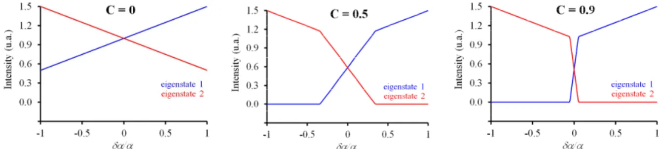
Figure 5 : Evolution of the intensities of the two modes as a function of the normalized circular dichroism of gain for three values of the nonlinear coupling constant: 0, 0.5 and 0.9.
5.4 Discussion
The simultaneous oscillation of the two eigenstates is possible only if the nonlinear coupling constant between these two eigenstates is inferior to 1, which is the case in VECSELs. The graphs in Fig. 5 illustrate how the intensities of the two eigenstates evolve with respect to the normalized gain circular dichroism for three values of the coupling constant: C = 0,
C = 0.5, and C = 0.9. When the coupling constant is zero, the intensities of the two eigenstates move independently and
are proportional to the normalized gain circular dichroism. When the coupling constant is non zero, a region where the two eigenstates are allowed to oscillate simultaneously appears (see Fig. 9 for C = 0.5). When the coupling constant approaches 1, the simultaneity region narrows down which favors a switch from one eigenstate to the other ,i.e., from one polarization state to the other. For example, in the case of C = 0.9, a gain dichroism as low as 10% is expected to enable a full switch of the laser polarization. The average gain of the active medium being of few percent in VECSELs and the coupling constant being approximatively 0.9, a gain circular dichroism less than 1/1000 should be sufficient to flip the laser polarization. Thus, unlike in spin-LEDs, the nonlinear coupling in the active medium due to the gain cross saturation between the two eigenstates is extremely favorable. Indeed, it acts as a lever enhancing the effectiveness of spin induced gain dichroism to trigger the polarization switching of the laser. In addition to this leverage effect, it must be reminded that the laser sustains the oscillation of two eigenstates whose polarizations are perfectly defined. This make the development of circularly polarized spin controlled VECSEL very attractive in terms of polarization purity as compared to Spin-LEDs.
6. EXPERIMENTAL DEMONSTRATION OF FULL POLARIZATION SWITCHING BASED ON VSPIN MODEL PREDICTIONS
Following the VSPIN model predictions, we have undertaken to prepare a VECSEL in the optimal configuration for reaching full polarization switching by spin injection. The ½-VCSEL gain chip, operating at 1 µm, is grown by MOCVD and has been fabricated by Centre de Nanosciences et de Nanotechnologies (C2N). The structure is maintained at 279K with a Peltier thermo-electric cooler. The pumping system consists in an 808 nm pigtail multimode laser diode delivering up to 2W and focused on the gain medium to a 100 µm-diameter spot at normal incidence. As sketched in Fig. 6, the optical cavity is composed of five mirrors including the ½-VCSEL DBR, two 99.9% reflectivity 50mm radius of
Proc. of SPIE Vol. 10540 105401S-11
Downloaded From: https://www.spiedigitallibrary.org/conference-proceedings-of-spie on 22 Jul 2020 Terms of Use: https://www.spiedigitallibrary.org/terms-of-use
CL
a
f
Polarizer 45° Faraday Isolator Polarimeter Head Fabry-Pérot Interferometer -OscilloscopeIJ4 Polarizer Powermete
Control Unit
Q+
a-Computer
curvature concave mirrors (M2, M3), and two plane mirrors (M1, M4) to close the cavity. The M-shaped optical cavity is necessary to accommodate a large Faraday rotator (10 cm long). Without the Faraday rotator, the laser exhibits a linear polarization whose orientation is defined by the residual linear birefringence in the active structure. Moreover, despite a 100% right (σ +) or left (σ +) circularly polarized pumping, the laser output polarization remains strictly linear as
expected form the VSPIN model. Moreover, the fact that only one polarization oscillates denotes the high value of the coupling constant between the two laser eigenstates.
Figure 6 : Experimental setup and characterization setup of the VECSEL.
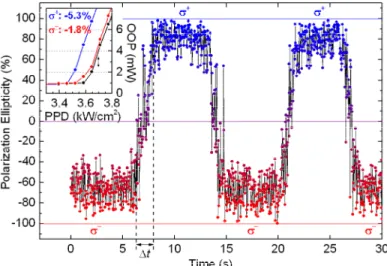
To make the laser eigenstates right and left circularly polarized, and thus overcome the residual linear birefringence, it is necessary to insert a non-reciprocal material into the cavity. We used a 45° TGG Faraday rotator anti-reflection coated at 1 µm. When manually changing the pump polarization from right to left circular polarization, we observed a corresponding switch from σ + to σ - of the laser polarization (see Fig 7). This witnesses a sufficient spin injection in the
active medium. We also observed a threshold reduction of few percent when pumping circularly compare to the linearly polarized pumping (inset of Fig. 7). This weak threshold reduction is directly linked to a gain dichroism of few percent. More importantly, the range of simultaneous oscillations of the two eigenstates is shown experimentally to be very narrow favoring then an easy switch from one eigenstate to the other even if ΔG is very low. As presented in Fig. 5, for C = 0.9, a normalized gain dichroism of about 10% is sufficient to tip over the polarization. The average gain of such a structure being around 1%, a gain dichroism of about 0.1% is sufficient to fully switch the laser polarization thanks to the leverage effect of the non-linear coupling.
Figure 7 : Time evolution of the laser output polarization ellipticity when switching the pump polarization from σ+ to σ-.
The inset presents the evolution at threshold of the OOP as a function of the PPD for different pumping polarization
Proc. of SPIE Vol. 10540 105401S-12
Downloaded From: https://www.spiedigitallibrary.org/conference-proceedings-of-spie on 22 Jul 2020 Terms of Use: https://www.spiedigitallibrary.org/terms-of-use
orientations: linear in black, σ+ in blue, and σ- in red. The transition time Δt corresponds to the time needed to rotate the
QWP of the pumping system.
7. CONCLUSION
The vectorial model we used to guide our research on the development and optimization of VCSEL based spin lasers is detailed. This model relies on the Jones formalism where the spin injection effect is phenomenologically taken into account as a gain circular dichroism. We show that the resonance condition for the field in the laser cavity yields two possible eigenpolarizations whose coexistence is ruled by the nonlinear coupling constant as defined by Lamb. The gain circular dichroism is intentionally considered low due to the unavoidable spin relaxation in semiconductor quantum wells. Under this condition, we show that the residual linear birefringence that is inherently present in any laser forbids the polarization to switch from one state to the other. The laser polarization is then mainly ruled by this linear birefringence, which forces the laser to operate in two possible linear polarizations oriented along the neutral axes of the birefringence. Increasing spin injection breaks the orthogonality between the two possible polarizations, which progressively align along a common direction oriented at 45° while staying linear. Increasing the spin injection further might lead to a peculiar situation, where the two possible polarizations are degenerated and correspond to a single linear polarization oriented at 45° with respect to the neutral axes of the linear birefringence. Above this point, i.e., for very efficient spin injection, the two permitted laser polarizations become elliptical and then circular with opposite directions. In practice, the coupling constant being high, one polarization will dominate. Thus, the laser provides a linear polarization whose orientation changes with increasing spin injection until it reaches 45°. To overcome this problem, due to the inherent presence of linear birefringence, we show that the laser has to be prepared so that its two polarization eigenstates are right-handed and left-handed circular, respectively. This is obtained by inserting a nonreciprocal effect within the laser cavity. The vectorial modelling shows that in this case a spin injection effect, even very low, can flip the laser polarization from one state to the other. The residual linear birefringence no longer determines the laser polarization eigenstates, but only introduces a slight change of ellipticity. The two possible polarizations being almost circular, spin injection directly acts on the differential gain between these polarizations unlike in the previous case where this differential gain was acting on the two eigenpolarizations at the same time. If the coupling constant is high enough, the oscillating mode is the one experiencing the highest gain. As a result, a small differential gain is now able to selectively favor either the left-handed or right-handed circular polarization.
We have already confirmed experimentally most of the predictions provided by the VSPIN model. In particular, the insertion of a nonreciprocal effect in the laser cavity is proved to be a very efficient way to hide the residual linear birefringence and thus to obtain a full polarization flip by spin injection in VECSELs [21]. However, the integration of a nonreciprocal material in a commercial laser product is not an easy task. Compensating the residual linear birefringence is an alternative solution that should be more affordable for integration. Combined with the leverage effect provided by the high coupling constant in VCESELs, an almost full polarization switch might be obtained even with inefficient spin injection provided that the linear birefringence is totally cancelled. This is the approach that we are currently pursuing.
ACKNOWLEDGEMENTS
This work was partially supported by the French National Research Agency through the project INSPIRE. The authors acknowledge Henri Jaffrès for fruitful discussions on spin dynamics in solid-state devices.
REFERENCES
[1] R. Fiederling, M. Keim, G. Reuscher, W. Ossau, G. Schmidt, A. Waag, and L. W. Molenkamp,“Injection and detection of a spin-polarized current in a light-emitting diode,” Nature 402, 787 (1999).
[2] X. Jiang, R. Wang, R. M. Shelby, R. M. Macfarlane, S. R. Bank, J. S. Harris, and S. S. P. Parkin, “Highly Spin-Polarized Room-Temperature Tunnel Injector for Semiconductor Spintronics using MgO(100),” Phys. Rev. Lett. 94, 056601 (2005).
[3] S. A. Crooker, D. D. Awschalom, J. J. Baumberg, F. Flack, and N. Samarth, “Optical spin resonance and transverse spin relaxation in magnetic semiconductor quantum wells,” Phys. Rev. B 56, 7574 (1997).
Proc. of SPIE Vol. 10540 105401S-13
Downloaded From: https://www.spiedigitallibrary.org/conference-proceedings-of-spie on 22 Jul 2020 Terms of Use: https://www.spiedigitallibrary.org/terms-of-use
[4] A. Garnache, A. Ouvrard, and D. Romanini, “Single-Frequency operation of External-Cavity VCSELs: Non-linear multimode temporal dynamics and quantumlimit,” Opt. Express 15, 9403 (2007)
[5] J. Lee, W. Falls, R. Oszwaldowski, and I. Zutic, “Spin modulation in semiconductor lasers,” Appl. Phys. Lett. 97, 041116 (2010).
[6] N. Gerhardt, S. Hovel, M. Hofmann, J. Yang, D. Reuter, and A. Wieck, “Enhancement of spin information with vertical cavity surface emitting lasers,” Electron. Lett. 42, 88 (2006).
[7] P. E. Faria Junior, G. Xu, G. Lee, N. C. Gerhardt, G. M. Sipahi, and I. Zutic, “Toward high-frequency operation of spin lasers,” Phys. Rev. B 92, 075311 ( 2015).
[8] J. Lee, S. Bearden, E. Wasner, and I. Žutić, “Spin-lasers: From threshold reduction to large-signal analysis,” Appl. Phys. Lett. 105, 042411 (2014).
[9] E. Wasner, S. Bearden, J. Lee, and I. Žutić “Digital operation and eye diagrams in spin-lasers,” Appl. Phys. Lett. 107, 082406 (2015).
[10] D. Basu, D. Saha, and P. Bhattacharya, “Optical polarization modulation and gain anisotropy in an electrically injected spin laser,” Phys. Rev. Lett. 102, 093904 (2009).
[11] S. Hovel, N. Gerhardt, M. Hofmann, J. Yang, D. Reuter, and A. Wieck, “Spin controlled optically pumped vertical cavity surface emitting laser,” Electron. Lett. 41, 251 (2005).
[12] M. Holub, J. Shin, S. Chakrabarti, and P. Bhattacharya, “Electrically injected spin-polarized vertical-cavity surface-emitting lasers,” Appl. Phys. Lett. 87, 091108 (2005).
[13] J. Rudolph, S. Döhrmann, D. Hägele, M. Oestreich, and W. Stolz, “Room-temperature threshold reduction in vertical-cavity surface-emitting lasers by injection of spin-polarized electrons,” Phys. Rev. Lett. 87, 241117 (2005).
[14] H. Ando, T. Sogawa, and H. Gotoh, “Photon-spin controlled lasing oscillation in surface-emitting lasers,” Appl. Phys. Lett. 73, 566 (1998).
[15] M. Travagnin, M.P. van Exter, A.K. Jansen van Doorn, and J.P. Woerdman, “Role of optical anisotropies in the polarization properties of surface-emitting semiconductor lasers,” Phys. Rev. A 54, 1647 (1996).
[16] M. Travagnin, M.P. van Exter, A.K. Jansen van Doorn, and J.P. Woerdman, “Erratum: Role of optical anisotropies in the polarization properties of surface emitting semiconductor lasers [phys. rev. a 54 , 1647 (1996)],” Phys. Rev. A 55, 4641(1997).
[17] J. Frougier, G. Baili, I. Sagnes, D. Dolfi, J.-M. George and M. Alouini, “Accurate measurement of the residual birefringence in VECSEL: Towards understanding of the polarization behavior under spin-polarized pumping,” Opt. Express 23, 9573 (2015).
[18] M. San Miguel, Q. Feng, and J. V. Moloney, “Light-polarization dynamics in surface-emitting semiconductor lasers,” Phys. Rev. A 52, 1728 (1995).
[19] A. Gahl, S. Balle, and M.S. Miguel, “Polarization dynamics of optically pumped vcsels,” IEEE J. of Quantum Electron. 35, 342 (1999).
[20] S. De, V. Potapchuk, and F. Bretenaker, “Influence of spin-dependent carrier dynamics on the properties of a dual-frequency vertical-external-cavity surface-emitting laser,” Phys. Rev. A 90, 013841 (2014).
[21] J. Frougier, G. Baili, M. Alouini, I. Sagnes, H. Jaffrès, A. Garnache, C. Deranlot, D. Dolfi, and J.M. George, “Control of light polarization using optically spin-injected vertical external cavity surface emitting lasers,” Appl. Phys. Lett. 103, 252402 (2013).
[22] A. Joly, G. Baili, M. Alouini, J-M. George, I. Sagnes, G. Pillet, and D. Dolfi, “Compensation of the residual linear anisotropy of phase in a vertical-external-cavity-surface-emitting laser for spin injection,” Opt. Lett. 42, 651-654 (2017).
[23] R.C. Jones, “A new calculus for the treatment of optical systems. I. Description and discussion of the calculus,” J. Opt. Soc. Am. 31, 488 (1941).
[24] A.E. Siegman, “lasers,” (University Science Books, 1986).
[25] A. Le Floch, G. Ropars, J. M. Lenormand, and R. Le Naour, "Dynamics of Laser Eigenstates," Phys. Rev. Lett. 52, 918 (1984).
[26] E. Collett, “Polarized light: fundamentals and applications,” (Dekker, 1993).
[27] C. Brosseau, “Fundamentals of Polarized Light: A Statistical Optics Approach,” (Wiley, 1998).
[28] S. Iba, S. Koh, K. Ikeda, and H. Kawaguchi, “Room temperature circularly polarized lasing in an optically spin injected vertical-cavity surface-emitting laser with (110) GaAs quantum wells,” Applied Physics Letters 98, 081113 (2011).
Proc. of SPIE Vol. 10540 105401S-14
Downloaded From: https://www.spiedigitallibrary.org/conference-proceedings-of-spie on 22 Jul 2020 Terms of Use: https://www.spiedigitallibrary.org/terms-of-use
[29] T. Fördös, K. Postava, H. Jaffrès, and J. Pištora, “Matrix approach for modeling of emission from multilayer spin-polarized light-emitting diodes and lasers,” J. Opt. 16, 065008 (2014).
[30] N. Ortega-Quijano, J. Fade, F. Parnet, and M. Alouini, “Generation of a coherent light beam with precise and fast dynamic control of the state and degree of polarization,” Opt. Lett. 42, 2898 (2017).
[31] Y. Ohno, R. Terauchi, T. Adachi, F. Matsukura, and H. Ohno, “Electron spin relaxation beyond D'Yakonov-Perel interaction in GaAs/AlGaAs quantum wells,” Physica, E 6, 817 (2000).
[32] J. Rudolph, D. Hägele, H. M. Gibbs, G. Khitrova, and M. Oestreich “Laser threshold reduction in a spintronic device,” Appl. Phys. Lett. 82, 4516 (2003).
[33] V. Pal, P. Trofimoff, B.-X. Miranda, G. Baili, M. Alouini, L. Morvan, D. Dolfi, F. Goldfarb, I. Sagnes, R. Ghosh, and F. Bretenaker, “Measurement of the coupling constant in a two-frequency VECSEL,” Opt. Express 18, 5008 (2010).
[34] M. Vallet, M. Brunel, M. Alouini, F. Bretenaker, A. Le Floch, et G.P. Agrawal, “Polarization self-modulated lasers with circular eigenstates,” Appl. Phys. Lett. 74, 3266 (1999).
[35] M. B. Willemsen, M. P. van Exter, and J. P. Woerdman, “Anatomy of a Polarization Switch of a Vertical-Cavity Semiconductor Laser,” Phys. Rev. Lett. 84, 4337 (2000).
[36] M. Sargent III M. O. Scully et W. E. Lamb, Jr., “Laser Physics,” (Addison-Wesley, Reading, MA 1974). [37] M. Brunel, M. Vallet, A. Le Floch, and F. Bretenaker, “Differential measurement of the coupling constant
between laser eigenstates,” Appl. Phys. Lett. 70, 2070 (1997).
[38] M. Alouini, F. Bretenaker, M. Brunel, A. Le Floch, M. Vallet, and Ph. Thony “Existence of two coupling constants in microchip lasers,” Opt. Lett. 25, 896 (2000).
[39] A. McKay, J.M. Dawes, and J.D. Park, “Polarisation-mode coupling in (100)-cut Nd:YAG,” Opt. Express 15, 16342-16347 (2007).
[40] G. Baili, L. Morvan, M. Alouini, D. Dolfi, F. Bretenaker, I. Sagnes, and A. Garnache, “Experimental demonstration of a tunable dual-frequency semiconductor laser free of relaxation oscillations,” Opt. Lett. 34, 3421 (2009).
Proc. of SPIE Vol. 10540 105401S-15
Downloaded From: https://www.spiedigitallibrary.org/conference-proceedings-of-spie on 22 Jul 2020 Terms of Use: https://www.spiedigitallibrary.org/terms-of-use