HAL Id: hal-03088301
https://hal.archives-ouvertes.fr/hal-03088301
Submitted on 26 Dec 2020
HAL is a multi-disciplinary open access
archive for the deposit and dissemination of
sci-entific research documents, whether they are
pub-lished or not. The documents may come from
teaching and research institutions in France or
abroad, or from public or private research centers.
L’archive ouverte pluridisciplinaire HAL, est
destinée au dépôt et à la diffusion de documents
scientifiques de niveau recherche, publiés ou non,
émanant des établissements d’enseignement et de
recherche français ou étrangers, des laboratoires
publics ou privés.
Field-induced circulation flow in magnetic fluids
Anton Musickhin, Andrey Yu. Zubarev, Maxime Raboisson-Michel, Gregory
Verger-Dubois, Pavel Kuzhir
To cite this version:
Anton Musickhin, Andrey Yu. Zubarev, Maxime Raboisson-Michel, Gregory Verger-Dubois, Pavel
Kuzhir. Field-induced circulation flow in magnetic fluids. Philosophical Transactions of the Royal
Society A: Mathematical, Physical and Engineering Sciences, Royal Society, The, 2020, 378 (2171),
pp.20190250. �10.1098/rsta.2019.0250�. �hal-03088301�
Field-induced circulation flow in magnetic fluids.
Anton Musickhin
1, Andrey Yu. Zubarev
1,2Maxim Raboisson-Michel
3,4,
Gregory Verger-Dubois
4and Pavel Kuzhir
3,
1Theoretical and Mathematical Physics Department, Institute of Natural Sciences and Mathematics, Ural Federal University, Lenin Ave, 51, Ekaterinburg, 620083, Russia,
2M.N. Mikheev Institute of Metal Physics of the Ural Branch of the Russian Academy of Sciences, Ekaterinburg, Russia
3 Université Côte d’Azur, CNRS UMR 7010, Institute of Physics of Nice, Parc Valrose, 06108 Nice, France 4 Axlepios Biomedical – 1ere Avenue 5eme rue, 06510 Carros, France
ORSID ID Andrey Zubarev 0000-0001-5826-9852
Keywords: Magnetic fluid; Oscillating magnetic field; Field-induced flow.
Summary
We present results of theoretical study of circulation flow in ferrofluids under the action of an alternating inhomogeneous magnetic field. The results show that the field with the amplitude about 17 kA/m and frequency 10s-1
can induce the mesoscopic flow with the velocity amplitude about 0.5mm/s. This mechanism can be used for intensification of drag delivery in blood vessels.
1. Introduction
The main problem of treatment of brain strokes is related to very slow diffusion of the thrombolytic drugs toward blood clots through blocked vessels. An American company Pulse Therapeutics has proposed a smart solution to this problem using magnetic micro- or nanoparticles entrained in motion by alternating magnetic fields and able to create recirculating flows in the blocked vessels [1]. These recirculating flows considerably enhance convective transport of the drug towards the clots. Only a few works have been published on this topic [2-4], so, the physical understanding of the origin of the recirculating or oscillatory flows created by moving and rotating magnetic particles is still lacking. To shed more light onto this problem, in this paper, we propose a theoretical model considering ferroparticle motion
*Author for correspondence ([email protected]).
†Present address: Department of Theoretical and Mathematical Physics, Ural Federal University,
R. Soc. open sci. article template
2 Insert your short title here
Phil. Trans. R. Soc. A.
and induced flows inside a channel under applied alternative non-homogeneous magnetic fields. The obtained amplitudes of the velocity and fluid displacement are compared to those required for efficient drug delivery to the blood clots in a real situation.
The aim of this work is theoretical study of circulation flows induced by an alternating magnetic field in a magnetic fluid filling a flat gap, which size in its plane is much more than the distance between the gap walls.
2. Mathematical model and the main approximations.
We consider an infinite flat gap of the thickness l filled with a ferrofluid, containing identical spherical ferroparticles. The alternating magnetic field is created by four solenoids, illustrated in Fig.1
.
Fig.1. Illustration of the model system .
Let m and M be the particle magnetic moment and saturated magnetization of its material; 𝑉𝑝 is the particle volume. It is supposed that the gap thickness l is much less than the solenoid diameter 𝐷 (𝑙 << 𝐷). We suppose that, initially, some drop of a ferrofluid is injected in the center of the considered model.
We will denote the local volume concentration of the particles as Ф(x,z,t) and, for maximal simplification of mathematics, consider the 2D approximation, when all physical events take place in the plane (x,z) shown in Fig.1. Additionally, we will neglect effects of the particles Brownian rotation. This means, we suppose that the Zeemen energy of the particle interaction with the field H is significantly more than the thermal energy kT. Note that, from the practical point of view, this case is the most interesting. Note, for the magnetite particles with diameter about 10-20nm this condition is fulfilled if the local H exceeds 10kA/m. That is easy achievable range of the field. Equations of flow of the magnetizable fluid at low Reynolds number can be presented as (see [5,6]): 𝜌𝜕𝑣𝑥 𝜕𝑡 = − 𝜕𝑝 𝜕𝑥+ 𝜂Δ𝑣𝑥+ 1 2 𝜕 𝜕𝑧Γ + 𝜇0𝑀Φ [cos 𝜃 𝜕 𝜕𝑧+ sin 𝜃 𝜕 𝜕𝑥] 𝐻𝑥 (1) 𝜌𝜕𝑣𝑧 𝜕𝑡 = − 𝜕𝑝 𝜕𝑧+ 𝜂Δ𝑣𝑧− 1 2 𝜕 𝜕𝑥Γ + 𝜇0𝑀Φ [cos 𝜃 𝜕 𝜕𝑧+ sin 𝜃 𝜕 𝜕𝑥] 𝐻𝑧 𝜕 𝜕𝑥𝑣𝑥+ 𝜕 𝜕𝑧𝑣𝑧= 0 Here Δ = 𝜕2 𝜕𝑥2+ 𝜕2
𝜕𝑧2 is the Laplace operator, 𝛤 = 𝜇0𝑀Φ(𝐻𝑧𝑠𝑖𝑛𝜃 − 𝐻𝑥cos 𝜃) is the magnetic torque, acting by unit volume of the ferrofluid; H is the local magnetic field in the fluid; 𝜃 is the angle between the particle magnetic moment m and the axis Oz, normal to the gap plane (see Fig.1). The third terms in the first two equations of (1) present the stress, which appear because of the magnetic torque 𝛤; the fourth one is the ponderomotive force, acting on the fluid from the side of the non-uniform field H.
Phil. Trans. R. Soc. A.
The boundary conditions for (1) are:
𝑣𝑥= 𝑣𝑧= 0 𝑎𝑡 𝑧 = 0, 𝑙 (2) 𝑣𝑥, 𝑣𝑧→ 0 𝑎𝑡 𝑥 → ∞
In the “no Brownian” approximation, equation for the angle 𝜃 reads [1] 𝜕𝜃 𝜕𝑡= 1 2( 𝜕𝑣𝑥 𝜕𝑧 − 𝜕𝑣𝑧 𝜕𝑥) − 1 6𝜂ΦΓ (3)
Note, the ratio Γ/Φ is magnetic torque with acts on the unite volume of the particle. Equation of continuity for the particles concentration can be written as:
𝜕
𝜕𝑡Φ + 𝑑𝑖𝑣 [Φ (𝐯 − 1
3𝜋𝜂𝑑∇𝑈)] = 𝐷∆Φ (4) 𝑈 = −𝜇0𝑀𝑉𝑝(𝐻𝑧cos 𝜃 + 𝐻𝑥sin 𝜃)
Here d is the particle diameter; U is the particle potential energy in the field H.
Below we will use the following estimates for the system parameters. We suppose that the particles are
magnetite, therefore 𝑀 ≈ 500𝑘𝐴/𝑚; diameter of the particle 𝑑 ≈ 15 − 20𝑛𝑚; volume concentration of the particles Φ~0.01; the angular frequency of the alternating field, 𝑐𝑟𝑒𝑎𝑡𝑒𝑑 𝑏𝑦 𝑡ℎ𝑒 𝑐𝑜𝑙𝑒𝑛𝑜𝑖𝑑 𝜔~10𝑠−1; the solenoid provides the field H inside the gap with the strength absolute value 𝐻 > 10𝑘𝐴/𝑚. The viscosity and density of the host medium are close to those of water ones, i.e. we suppose 𝜂~10−3𝑃𝑎 ∙ 𝑠; 𝜌~103𝑘𝑔/𝑚3 . The gap thickness is estimated as 𝑙~1𝑚𝑚.
Analytical solution of the whole system (1-4) is impossible. However, serious simplifications can be achieved by using the mentioned estimates for the system characteristics. First of all, from the mathematical point of view, the fluid flow is provoked by the last two terms in the Navier-Stocks equations of (1). These terms are proportional to the small concentrations Φ of the particles. Therefore, roughly, the scaling relation 𝑣~Φ must be held and the terms 1
2( 𝜕𝑣𝑥
𝜕𝑧 −
𝜕𝑣𝑧
𝜕𝑥) , Φ𝑣 can be considered as the smallest ones in eqs. (3), (4).We will neglect these terms.
Let us present the local concentration of the particles as Φ(𝑥, 𝑧, 𝑡) = Φ0(𝑥, 𝑧) + 𝜑(𝑥, 𝑧, 𝑡) where Φ0~0.01 is the initial volume concentration of the particles in the drop. Estimates show that in the field with the strength
𝐻~10𝑘𝐴/𝑚 and the spatial scale 𝐷~10−2𝑚 the characteristic time 𝜏 = 3𝜋𝜂𝑑𝐿2
𝜇0𝑀𝑉𝑝𝐻 of magnetophoretic migration of
the magnetite particle with diameter 20nm at the distance 𝐷 is more than 5 ∙ 105𝑠 ≈ 140 ℎ𝑜𝑢𝑟𝑠. That significantly exceeds the time, presenting interest from the viewpoint of the drug delivery technology. Therefore, at least in the first approximation, one can neglect the term 𝜑 as compared with Φ0 and suppose that for the time, presenting interest, the equality Φ = Φ0(𝑥, 𝑧) is held. In principle, the drop shape can be varied because of the convective motion of the ferrofluid particles in the generated circulation flow. Discussion of this factor is given in the Conclusion.
Neglecting the term 1 2(
𝜕𝑣𝑥
𝜕𝑧 −
𝜕𝑣𝑧
𝜕𝑥) and by using the explicit form for the torque Г, one can rewrite eq. (3) as: 𝜕𝜃
𝜕𝑡= −
𝜇0𝑀
6𝜂 (𝐻𝑧𝑠𝑖𝑛𝜃 − 𝐻𝑥cos 𝜃)
(6)
For convenience one can present the first two equations of (1) as:
𝜌𝜕𝑣𝑥 𝜕𝑡 = − 𝜕𝑝 𝜕𝑥+ 𝜂Δ𝑣𝑥+ 𝜇0𝑀ΦG𝑥 (7) 𝜌𝜕𝑣𝑧 𝜕𝑡 = − 𝜕𝑝 𝜕𝑧+ 𝜂Δ𝑣𝑧+ 𝜇0𝑀ΦG𝑧 𝐺𝑥 = 1 2 𝜕 𝜕𝑧(𝐻𝑧𝑠𝑖𝑛𝜃 − 𝐻𝑥𝑐𝑜𝑠𝜃) + [𝑐𝑜𝑠𝜃 𝜕 𝜕𝑧+ 𝑠𝑖𝑛𝜃 𝜕 𝜕𝑥] 𝐻𝑥 𝐺𝑧= − 1 2 𝜕 𝜕𝑥(𝐻𝑧𝑠𝑖𝑛𝜃 − 𝐻𝑥𝑐𝑜𝑠𝜃) + [𝑐𝑜𝑠𝜃 𝜕 𝜕𝑓 𝑧+ 𝑠𝑖𝑛𝜃 𝜕 𝜕𝑥] 𝐻𝑧
We will suppose that the solenoids create the field with the same angular frequency 𝜔 and the components 𝐻𝑥= (𝐻01𝑥(𝑥, 𝑧) − 𝐻04𝑥(𝑥, 𝑧))𝑐𝑜𝑠𝜔𝑡 + (𝐻02𝑥(𝑥, 𝑧) − 𝐻03𝑥(𝑥, 𝑧))𝑠𝑖𝑛𝜔𝑡 (8) 𝐻𝑧= (𝐻01𝑧(𝑥, 𝑧) − 𝐻04𝑧(𝑥, 𝑧))𝑐𝑜𝑠𝜔𝑡 + (𝐻02𝑧(𝑥, 𝑧) − 𝐻03𝑧(𝑥, 𝑧))𝑠𝑖𝑛𝜔𝑡
R. Soc. open sci. article template
4 Insert your short title here
Phil. Trans. R. Soc. A.
Here 𝑯01, 𝑯02, 𝑯03 and 𝑯04 are amplitudes of the fields created by the lower, upper, left and right solenoids in Fig.1. The relations (8) mean that the north pole of the left solenoid in Fig.1 is situated in front of the south pole of the right one. The same is for the magnets which are above and below the gap with the fluid.
It follows from eq.(6) that, in the order of magnitude, the characteristic time 𝜏𝐻 of the angle 𝜃 relaxation to the given field H is 𝜏𝐻~𝜂/𝜇0𝑀H . Suppose that absolute value of the field in the gap has the typical magnitude 𝐻~10𝑘𝐴/𝑚, the particles are magnitude (𝑀~500𝑘𝐴/𝑚) and the carrier liquid is water (𝜂~ 10−3𝑃𝑎 ∙ 𝑠 ). In this case 𝜏
𝐻~10−6s . The typical value of the angular frequency for the experiments like that is 𝜔~10𝑠−1, therefore, the field alternation period is about 0.1s-1. Therefore, the rate of the field alternation is about five decimal orders less than the rate of 𝜃
relaxation. This means that in any moment of time the angle 𝜃 has practically the value 𝜃0 equilibrium with respect to the field H at the given time t; this angle is determined by the relations
cos 𝜃0=𝐻𝑧
𝐻 , sin 𝜃 0=𝐻𝑥
𝐻 (9) 𝐻 = √𝐻𝑥2+ 𝐻𝑧2
Taking into account, we use 𝜃 = 𝜃0 in eq. (9). In this approximation, with account of the standard magnetostatic relation 𝑟𝑜𝑡𝑯 = 0, one gets from (9):
𝐺𝑥 = 𝜕
𝜕𝑥𝐻; 𝐺𝑧= 𝜕
𝜕𝑧𝐻 (10) This is convenient to introduce the current function Ψ so that
𝑣𝑥= 𝜕
𝜕𝑧Ψ, 𝑣𝑧= − 𝜕
𝜕𝑥Ψ (11) Combining (7) and (11), taking into eq. (10), after transformations we come to the following equation with respect to
Ψ : 𝜌𝜕𝑄 𝜕𝑡 = 𝜂Δ𝑄 + 𝜇0𝑀 [ 𝜕 𝜕𝑥𝐻 ∙ 𝜕 𝜕𝑧Φ − 𝜕 𝜕𝑧H ∙ 𝜕 𝜕𝑥Φ] (12) 𝑄 = ΔΨ
The boundary conditions for equation (12) are: z=0,l 𝜕Ψ
𝜕𝑥=
𝜕Ψ
𝜕𝑧 = 0 (13)
t=0, Ψ = 0
Taking into account the relation 𝐷 >> 𝑙 between the velocity 𝑣 scales in the x (D) and z (l) directions, we get the strong inequalities
𝜕2Ψ
𝜕𝑧2 >>
𝜕2Ψ
𝜕𝑥2
Therefore, in eq. (9) one can put 𝑄 =𝜕2Ψ
𝜕𝑧2; Δ𝑄 =
𝜕4Ψ
𝜕𝑧4
(14)
And to present this equation as: 𝜕𝑄 𝜕𝑡 = 𝜈 𝜕2𝑄 𝜕𝑧2+ 𝑓; (15) 𝑓 =𝜇0𝑀 𝜌 [ 𝜕 𝜕𝑥𝐻 ∙ 𝜕 𝜕𝑧Φ − 𝜕 𝜕𝑧𝐻 ∙ 𝜕 𝜕𝑥Φ]
3. Solution of equation (12); results and discussions.
We suppose that the spatial scale of the function f in the x direction is much more than that in z direction.
This is justified by configuration of the solenoids, which create the field H and the ferrofluid drop distribution in the gap. Indeed, the spatial scale of the function f is determined by the solenoid diameter D and their distances a,b from the ferrofluid drop. All these scales usually are much more than diameter of the blood vessel, which is modeled here by the gap with the thickness l. Thus, at the distance l ., the function f changes very weakly and, in the first approximation, one can neglect dependence of f on the coordinate z.
Taking into account that the function f is periodical with the period 2𝜋/𝜔 , we can expand this function in the Fourier series as (see, for example, ref. [7]):
Phil. Trans. R. Soc. A. 𝑓 = 2𝑓𝐶0+ ∑𝑛=1(𝑓𝐶𝑛cos(𝜔𝑛𝑡) + 𝑓𝑆𝑛sin(𝜔𝑛𝑡)) (16) 𝑓𝐶𝑛= 1 𝑇∫ 𝑓(𝑥, 𝑡)cos(𝜔𝑛𝑡)𝑑𝑡 𝑇/2 −𝑇/2 𝑓𝑆𝑛= 1 𝑇∫ 𝑓(𝑥, 𝑡)sin(𝜔𝑛𝑡)𝑑𝑡 𝑇/2 −𝑇/2 Ψ =1 2ΨС0+ ∑(ΨС𝑛cos(𝜔𝑛𝑡) + ΨS𝑛sin(𝜔𝑛𝑡)) ∞ 𝑛=1
By using (16) in (14) and (15), we come to the relations:
𝛹𝐶𝑛= −𝐴𝑛 𝑒𝑘𝑧𝑐𝑜𝑠𝑘𝑧 2𝑘2 − 𝐵𝑛 𝑒𝑘𝑧𝑠𝑖𝑛𝑘𝑧 2𝑘2 − 𝐶𝑛 𝑒−𝑘𝑧𝑐𝑜𝑠𝑘𝑧 2𝑘2 − 𝐷𝑛 𝑒−𝑘𝑧𝑠𝑖𝑛𝑘𝑧 2𝑘2 + 𝐿1𝑛𝑧 + 𝐿2𝑛− 𝑓𝑆𝑛 2(𝜔𝑛)𝑧 2 (17) 𝛹𝑆𝑛= 𝐴𝑛 𝑒𝑘𝑧𝑠𝑖𝑛𝑘𝑧 2𝑘2 − 𝐵𝑛 𝑒𝑘𝑧𝑐𝑜𝑠𝑘𝑧 2𝑘2 − 𝐶𝑛 𝑒−𝑘𝑧𝑠𝑖𝑛𝑘𝑧 2𝑘2 + 𝐷𝑛 𝑒−𝑘𝑧𝑐𝑜𝑠𝑘𝑧 2𝑘2 + 𝑁1𝑛𝑧 + 𝑁2𝑛+ 𝑓𝐶𝑛 2(𝜔𝑛)𝑧 2 𝑘 = √2𝜈𝜔
Here 𝐴𝑛,…, 𝑁2𝑛 are constants of integration, to be determined. The boundary conditions (13) can be rewritten in the form z=0,l 𝜕Ψ𝐶𝑛
𝜕𝑧 = 0,
𝜕Ψ𝑆𝑛
𝜕𝑧 = 0, ΨC𝑛= 0, ΨS𝑛= 0 . (18) Combining eqs. (17) and (18), we come to a system of eight linear equations with respect to eight variations
An,…,N2n. Analytical solution of this systems is too cumbersome; however, the numerical calculations can not present a problem.
Having the coefficients An,…,N2n found, by using eq. (11), we determine the velocity components 𝑣𝑥,𝑧.
Results and discussion.
For definiteness we supposed the the spatial distribution of the particles obey to the Gaussian distribution
Φ = Φ0𝑒𝑥𝑝 [−
(𝑥2+(𝑧−𝑙2)
2
)
𝜎2 ] (19)
This formula means that in the vicinity of the middle of the gap there is a dense cloud of ferrofluid with the maximal 𝑣𝑜𝑙𝑢𝑚𝑒 𝑐𝑜𝑛𝑐𝑒𝑛𝑡𝑟𝑎𝑡𝑖𝑜𝑛Φ0 at point (0, 𝑙/2) ; 𝜎 is dispersion of this distribution. It should be noted that the spatial distribution (19) is used here just as a model one. Any other, more relevant to a concrete experimental situation, can be used for the calculations in the frame of the suggested approach.
To calculate the components of amplitude 𝑯01 of the field, created by the solenoid 1 in Fig.1, using the Biot– Savart law. In cylindrical coordinates it has the form
𝐻01𝑥(𝑥, 𝑧) = 𝐼 ∙ 𝐷 ∙ 𝑁 8𝜋ℎ ∫ 𝑑𝑧′ ( ∫ (𝑧 − 𝑧′) cos 𝜑 [(𝑧 − 𝑧′)2+ (𝐷 2sin 𝜑) 2 + (𝑥 −𝐷2cos 𝜑) 2 ] 3/2𝑑𝜑 2𝜋 0 ) −𝑎 −(ℎ+𝑎) 𝐻01𝑧(𝑥, 𝑧) = 𝐼 ∙ 𝐷 ∙ 𝑁 8𝜋ℎ ∫ 𝑑𝑧′ ( ∫ 𝐷 2− 𝑥 cos 𝜑 [(𝑧 − 𝑧′)2+ (𝐷 2sin 𝜑) 2 + (𝑥 −𝐷2cos 𝜑) 2 ] 3/2𝑑𝜑 2𝜋 0 ) −𝑎 −(ℎ+𝑎)
R. Soc. open sci. article template
6 Insert your short title here
Phil. Trans. R. Soc. A.
where 𝐼 is the current in the solenoid, ℎ is its height, 𝑁 is the number the solenoid coils and 𝑎 is the distance from solenoid to the gap. This formula represents the field components for the lower solenoid, for the other solenoids these components have been determined similarly
Fig. 2. Longitudinal velocity component 𝑣𝑥 vs. 𝑧 coordinate at a fixed 𝑥 = 10 𝑚𝑚 𝑖𝑛 𝐹𝑖𝑔. 1.
Red line: time 𝑡 = 0.5 𝑠; blue one: 𝑡 = 1 𝑠. The field angular frequency 𝜔 = 10𝑠−1. Volume concentration of the particles in the drop center Φ0= 0.01; the dispersion 𝜎 = 1 𝑐𝑚; the solenoid characteristics are identical for all
solenoids: diameter D=1cm; current 𝐼 = 10 𝐴; height h=1 𝑐𝑚; number of coils 𝑁 = 104 . The distances, shown in Fig. 1:
𝑎 = 𝑏 = 5 𝑐𝑚; the gap thickness l=1mm.
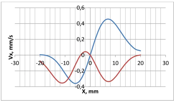
Fig. 3. Longitudinal velocity component 𝑣𝑥 vs. 𝑥 coordinate at a fixed 𝑧 = 𝑙/8 in Fig. 1. Red line: time 𝑡 = 0.5 𝑠; blue one: 𝑡 = 1 𝑠. The other parameters are the same as in Fig. 2
-0,6
-0,4
-0,2
0
0,2
0,4
0,6
0
0,2
0,4
0,6
0,8
1
1,2
Vx,
mm/
s
Z, mm
-0,4
-0,2
0
0,2
0,4
0,6
-30
Vx,
-20
-10
0
10
20
30
mm/
s
X, mm
Phil. Trans. R. Soc. A.
Note that for the system parameters, corresponding ti Figs.2,3, the amplitude of absolute value of the field in the gap center is about 17kA/m
4. Conclusions
We present theoretical model of magnetically induced circulation flow in a flat channel filled by a Newtonian liquid and a drop of ferrofluid. The results show that oscillating magnetic field with amplitude about
17 kA/m and frequency about 10s-1 in the channel with the wideness 1mm can induce circulating flow with the the
velocity amplitude about 0.5mm/s.
Let us discuss now the approximation of the permanent shape of the ferrofluid drop. Since the magnetophoretic displacement of the ferrofluid particles is neglected, the drop shape can be changed only because of the convective effects. In the order of magnitude, the displacement 𝛿𝑟 of the drop particles for the field period satisfies to the relation 𝛿𝑟 ≤ 𝑣𝑚𝑎𝑥2𝜋/𝜔 , where 𝑣𝑚𝑎𝑥 is maximal value of the velocity. Our results give 𝑣𝑚𝑎𝑥~0.5𝑚𝑚/𝑠 . By using 𝜔~10𝑠−1, one gets 𝛿𝑟 ≤ 0.3 𝑚𝑚 . This is much less than the used characteristic size 𝜎~1𝑐𝑚 of the drop. Therefore, the simplification of the permanent shape of the drop is justified, at least, as the first approximation.
Funding Statement
The work was supported by the Russian Fund of Basic Researches, project 19-31-90003 and by French “Agence Nationale de la Recherche”, Project Future Investments UCA JEDI, No. ANR-15-IDEX-01 (projects ImmunoMag and MagFilter)
.
Data Accessibility Competing Interests
We have no competing interests We have no competing interests.
References
1.Creighton, Francis M. 2012."Magnetic-based systems for treating occluded vessels." U.S. Patent No. 8,308,628. 13 Nov.
2.Clements, M. J. 2016. A mathematical model for magnetically-assisted delivery of thrombolytics in occluded blood vessels for ischemic stroke treatment (Doctoral dissertation, Texas University).
3.Gabayno, J. L. F., Liu, D. W., Chang, M., & Lin, Y. H. 2015. Controlled manipulation of Fe 3 O 4 nanoparticles in an oscillating magnetic field for fast ablation of microchannel occlusion. Nanoscale, 7(9), 3947-3953.( doi: 10.1039/x0xx00000x)
4.Li, Q., Liu, X., Chang, M., & Lu, Z. (2018). Thrombolysis Enhancing by Magnetic Manipulation of Fe3O4
Nanoparticles. Materials, 11(11), 2313, 12p.
5. Rosensweig, R, 1985, Ferrohydrodynamics. (Cambridge, New York)
6. Landau, L., Lifshitz, E., 1960, Electrodynamics of Continuum Media. (Pergamon Press, London) 7. Farlow, S.J., Partial Differential Equations for Scientists and Engineers (J.Wiley and Sons, 1982)
Creighton, Francis M. "Magnetic-based systems for treating occluded vessels." U.S. Patent No. 8,308,628. 13 Nov. 2012.
Figure captions
Figure 1 Illustration of the model system
8
Phil. Trans. R. Soc. A.
Red line: at time 𝑡 = 0.5 𝑠; blue one: 𝑡 = 1 𝑠. The field angular frequency 𝜔 = 10𝑠−1. Volume concentration of the particles in the drop center Φ0= 0.01; the dispersion 𝜎 = 1 𝑐𝑚; the solenoid characteristics: diameter D=1cm; curent 𝐼 = 10 𝐴; height h=1 𝑐𝑚; number of coils 𝑁 = 104 for all solenoids. The distances, shown in Fig. 1:
𝑎 = 𝑏 = 5 𝑐𝑚; the gap thickness l=1mm.
Figure 3. Longitudinal velocity component 𝑣𝑥 vs. 𝑥 coordinate at a fixed 𝑧 = 𝑙/8 𝑖𝑛 𝐹𝑖𝑔. 1. Red line: at time 𝑡 = 0.5 𝑠; blue one: 𝑡 = 1 𝑠. The other parameters are the same as in fig. 2
Note that for the system parameters, corresponding ti Figs.2,3, the amplitude of absolute value of the field in the gap center is about 17kA/m