HAL Id: hal-00911315
https://hal.archives-ouvertes.fr/hal-00911315
Submitted on 29 Nov 2013
HAL is a multi-disciplinary open access
archive for the deposit and dissemination of
sci-entific research documents, whether they are
pub-lished or not. The documents may come from
teaching and research institutions in France or
abroad, or from public or private research centers.
L’archive ouverte pluridisciplinaire HAL, est
destinée au dépôt et à la diffusion de documents
scientifiques de niveau recherche, publiés ou non,
émanant des établissements d’enseignement et de
recherche français ou étrangers, des laboratoires
publics ou privés.
Hybrid polyaniline-coated sepiolite nanofibers for
electrorheological fluid applications
Jessica Alves Marins, Francoise Giulieri, Bluma Guentther Soares, Georges
Bossis
To cite this version:
Jessica Alves Marins, Francoise Giulieri, Bluma Guentther Soares, Georges Bossis. Hybrid
polyaniline-coated sepiolite nanofibers for electrorheological fluid applications. Synthetic Metals, Elsevier, 2013,
185, pp.9-16. �hal-00911315�
Hybrid polyaniline-coated sepiolite nanofibers for electrorheological fluid applications
Jéssica Alves Marins1-2#, Françoise Giulieri 2, Bluma Guenther Soares 1 and Georges Bossis 2
1Universidade Federal do Rio de Janeiro, Instituto de Macromoléculas - Centro de Tecnologia, Bl. J, Ilha do Fundão
21945-970, Rio de Janeiro, RJ, Brasil
2Université de Nice-Sophia Antipolis, Laboratoire de Physique de la Matière Condensée, CNRS, UMR 6622, UNSA, Parc
Valrose 06108, Nice cedex 2, France
ABSTRACT. Hybrid materials constituted by sepiolite covered with polyaniline (PAni) with different compositions have
been prepared using two simple methods: bulk and slurry oxidative polymerization. The hybrid nanofibers were characterized by Fourier transform-infrared (FTIR) spectroscopy, transmission electron microscopy (TEM), thermo-gravimetric analysis (TGA), electrical conductivity, dielectric spectroscopy analysis and electrorheological response. Fiber-based nanocomposites with PAni nanoparticles well adhered to the sepiolite surface were successfully prepared by slurry polymerization. The best recovering of the nanofibers was observed in nanocomposites containing 46 wt% of PAni, (SP 50:50s sample) as indicated by FTIR and TEM and quantified by TGA analysis. Also the best electrorheological response was obtained with the corresponding suspensions containing 10 wt% of the hybrid material suspended in castor oil. The values of the field induced shear modulus in the linear viscoelastic region : G' = 536 kPa at E=2 kV/mm is higher than those found for the suspensions of pure components, PAni or sepiolite, and one of the best values obtained with conventional ER fluids. A model to estimate the interaction between two nanofibers has been proposed considering the length and thickness of the nanofiber, calculated by TEM.
KEYWORDS. electrorheology, nanofibers, polyaniline
1.
IntroductionElectrorheological fluids ERF are colloidal suspensions of polarizable organic or inorganic particles dispersed in a non-conducting liquid such as silicone oil, kerosene, paraffin, vegetable oil or halogenated hydrocarbon [1, 2]. Under the action of an electric field, the suspended particles in a non-polar fluid align along the field direction and form fibril-like microstructures which drastically increase the apparent viscosity and yield stress of the fluid. This behavior characterizes the electrorheological effect [3, 4], whose effect can be modeled by the Bingham [5] or Cho-Choi-Jhon model [2]. Many kinds of particles are used in the preparation of ERF, like cellulose, silica, zeolites, starch and titania [6]. These particles
feature the fluid as hydrous ERF. The water acts as an additive, but this system presented some disadvantages like evaporation of water and electric breakdown. More recently anhydrous ERF have been studied to improve their performance and the most common particles are made of conducting polymer like polyaniline, copolyaniline and polypyrrole [7].
Polyaniline (PAni) presents good electrical conductivity, which can be controlled through the pH value, easiness of preparation, relatively low density, stability to the heat and to the air, and low production costs. These characteristics made polyaniline to be considered one of the most versatile and the cheapest conducting polymer material, for using in ERF. However after many investigations the use of polyaniline did not obtain great success because of the low yield stress, colloidal instability and mainly due to the too high current density of the corresponding fluids. In order to solve these problems it was proposed to coat polyaniline on inorganic particles or insulating polymer. Choi et al. [8], Lim et al. [9] and Song et al. [10] prepared PAni/Clay composites, which presented irregular morphology and good ER effect. Different PAni/silica composites have also been employed in ERF. For instance, silica nanoparticle decorated with conducting polyaniline fibers was used in ERF by Liu et al. [11], but a better ER effect was obtained with pure PAni fiber whereas the composite presented instability in the chain-like structure as a function of shear rate. The same group prepared PAni/nanosilica nanocomposites, and in this case the nanocomposites performed better [12]. PAni coated with insulating polymer as: polystyrene (PS) microspheres with PAni [13] has been also investigated. This system presented improved yield stress with a linear behavior with the electrical field strength.
The present work deals with the development of sepiolite coated with polyaniline and the evaluation of this new hybrid material as an effective component for electrorheological fluids. The motivation of this present work is based on foreknowledge that elongated particles performs better on ER properties than spherical particles, because the dipole moment is larger for elongated particles than for spherical particles of the same size and polarizability [14]. An approaching system based on a PAni coating of aluminosilicate nanotubes of aspect ratio of about ten was recently explored but it did not gave higher ER effect than other systems based on PAni [15] Here we used sepiolite fibers which have a larger aspect ratio (1-5 m in length and 20-40 nm in diameter) and no conductivity. The sepiolite consists of mineral clay of hydrated magnesium silicates. Additionally sepiolite fiber surface is covered with silanol groups spaced 5
Ǻ apart, and external channels that are covered on one or two sides with Mg(OH2)2. The internal channels are covered
with Mg(OH2)2 on two sides and with Si-O-Si on the other two sides, these channels are filled with zeolitic water [16, 17].
The surface silanol groups allow building hydrogen bonding with PAni without the needs to add compatibilizing agent. For the development of a good coating of polyaniline on sepiolite surface, two different synthetic methods were used; the first one is called solid-solid and bulk polymerization, it consists of a mechanochemical adsorption that occurs between powders in the solid state [18, 19]. The second method is the slurry polymerization. This kind of polymerization
is performed in two phases, the first one consisted of the monomer and initiator solution and the second phase is formed when the polymer chains grows, and lose their affinity with the solvent resulting in polymer precipitate. Three concentration were tested 90:10, 70:30 and 50:50 weight ratio sepiolite:aniline. Dielectric properties were investigated in correlation with ER effect. The flow curve and dynamic viscoelastic tests were made as well as strain and frequency sweeps. The pure PAni fiber was analyzed for comparison [20].
2.
Experimental section2.1 Materials
Aniline (Ani) (analytical grade), ammonium peroxydisulfate (APS) (analytical grade), ortho phosphoric acid (Ph) (analytical grade), ammonium hydroxide NH4OH (analytical grade) all from Sigma-Aldrich and sepiolite (S9 grade,
Tolsa) were used without purification; a previous method of disaggregation was made using 10% of sepiolite in water was submitted to an ultrasound treatment for 40 min operating at 28% amplitude pulse 2/2sec and after this solution was dried
at 100 °C. De ionized water (18.2 M .cm) was employed in all experiments
2.2 Synthesis of PAni/Sepiolite by bulk polymerization
Sepiolite was milled in a mortar during 15 minutes Then the aniline was slowly added and, after obtaining a visually homogeneous powder, the H3PO4 was added. When the medium became clear the APS was added and mixing was
continued until a light pink color appeared. The reaction recipes are indicated in the Table 1. The sepiolite fibers aniline, phosphoric acid and APS were periodically mixed until the formation of a dark green powder. The dark green powder was poured into acetone, filtered and re-dispersed in aqueous solution containing 0.1M of NH4OH, kept under agitation for 4
h and dried at 70° C.
2.3 Synthesis of PAni/Sepiolite by slurry polymerization
Different amounts of sepiolite were dispersed in water (150 mL) using an ultrasound tip. Then a mixture of aniline (0.001 mol) and H3PO4 (0.0013 mol) was dissolved in 50 mL of water, and the resulting dispersion was ultrasonicated for
20 min with the help of a Vibracell 75041 - Bioblock scientific ultrasonic apparatus equipped with an ultrasound tip and operating at 28% amplitude pulse 2/2 sec. After 24 hours without stirring, 10 mL of an aqueous solution containing 0.0013 mol of APS were quickly added and the reaction medium was submitted to an ultrasound treatment for 20 min operating at 28% amplitude pulse 2/2sec. The polymerization was carried out at room temperature without stirring for
different times (Table 1). The dark green precipitate was poured into acetone, filtered and re-dispersed in aqueous solution containing 0.1M of NH4OH, kept under agitation for 4 h and dried at 70° C.
Table 1. Amounts of reactive used to prepared polyaniline and the reaction time
Sample Sepiolite (g) Ani (g) H3PO4 (g) APS (g) Reaction time
Bulk (b) Slurry (s)
SP90:10 0.9 0.1 0.14 0.33 72h *
SP70:30 0.7 0.3 0.42 0.98 24h 24h
SP50:50 0.5 0.5 0.71 1.65 4h 4h
* No product was obtained after 72h of reaction 2.4 Characterization
The micrographs of the sepiolite and polyaniline coated sepiolite were recorded from a JEOL- 1400 transmission electronic microscope, operating at 90kV. A diluted dispersion of the particles in water was first obtained by sonication. This dispersion was deposited on an amorphous polymer coated-copper grid.
Fourier transformed Infrared spectra (FTIR) were recorded in Perkin-Elmer Paragon 1000 spectrometer. Sepiolite, PAni and their mixtures were characterized by diffuse reflection infrared spectroscopy (DRIFT, minidiff plus diffuse reflectance acquired from Eurolabo). The powder mixed with KBr was placed in the cup and the background spectrum of KBr was subtracted. All transmittance spectra were taken at a resolution of 4 cm-1 for 64 scans from 4000 to 400 cm-1.
Thermo-gravimetric analysis was performed in a TA Instruments Q50 V20.10 Build 36 analyzer operating at a heating rate of 20° C/min, under nitrogen atmosphere (balance gas: nitrogen 40.0 mL/min and sample gas: nitrogen 60.0 mL/min) The TGA profiles were recorded in the temperature range 50–700° C. The weight of the sample used was about 9–11 mg in all the cases.
To determine the dielectric constant and conductivity, a pellet was made from the powder with a surface area 1.33x10⁻⁴
m2 and thickness 4x10⁻⁴ m. The measure was made with an AC impedance bridge using a Solartron SI 1260 gain phase
analyzer, interfaced to a Solartron 1296 dielectric interface. The measurements were carried out in a frequency range of 0.01 Hz to 100 kHz with 2V oscillating voltage.
Rheological measurements were performed using the Anton Paar Instruments Physical MCR 301, rheometer with electrorheological accessory, (Generator Model 609E-6 High voltage amplifier TREK with Multimeter Hameg Instruments - AC) plate-plate geometry (PP50/E-SN12613 gap 1 mm). The suspensions for ER measurements were prepared by dispersing pure PAni, SP70:30s and SP50:50s at 10% vol. in castor oil, from Sigma Aldrich, with the help of ultrasonic apparatus operating at 20% amplitude for 2 min.
3.
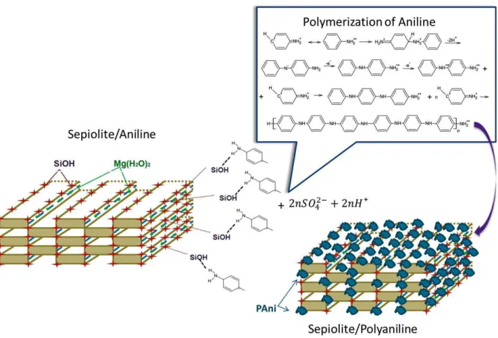
Results and discussionPAni/Sepiolite fibers were obtained by aniline polymerization in the presence of sepiolite. This method allowed the interfacial interaction between the aniline and the sepiolite surface. The schematic diagram of the polymerization of the aniline is shown in the Figure 1. The –OH groups at the sepiolite surface interact with the aniline monomer, through hydrogen bond between –NH2 of aniline and –OH of sepiolite. This same interaction is reported in the study of sepiolite
with polyimide [21] and the other studies of polyaniline coated cellulose fibers [22]
Figure 1. Schematic diagram of the formation of polyaniline at the surface of sepiolite
3.1 PAni/Sepiolite by bulk polymerization
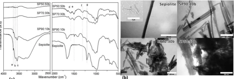
Figure 2a compares the FTIR spectra of PAni/sepiolite made by bulk polymerization at different concentrations. The
band a, at 3688 cm-1, is assigned to the hydroxyl stretching vibrations of Mg-OH structural group. The larger bands b and c at 3622 and 3555 cm-1 are associated with the coordinated water ν–OH [23]. These bands disappeared in the SP70:30b
and SP50:50b, samples, indicating that sepiolite is completely coated by PAni chains at these compositions. The SP90:10b sample presents these bands because the amount of PAni is not enough to coat the sepiolite fibers. The band d and e at 1576 and 1497 cm-1 are ascribed to the quinoid and benzonoid rings respectively, related to the polyaniline
component [24]. These bands are very weak in SP90:10b. The band f at 1307cm-1 is attributed to the C-N+ bond
corresponding to the π-electron induced in the polyaniline chain by protonation [18, 25]. The band g at 1209 cm-1 is
related to the Si-O bond of sepiolite. This assignment is apparent in the SP90:10b sample, but less clear in SP70:30b and
SP50:50b These results are hints that the sepiolite was not completely coated in the SP90:10b sample or that the polymerization of aniline produced oligomers.
The TEM micrographs of PAni/sepiolite and pure sepiolite are illustrated in Figure 2b. Sepiolite presents the TEM pictures of the fibers. Their cross section is rectangular about 20x40 nm and their average length is about one micron. The
SP90:10b sample exhibits slight agglomerates of fibers but it was not possible to observe the polyaniline coating the sepiolite surface, as also indicated in the FTIR results. SP70:30b and SP50:50b images show presence of large agglomerates constituted by polyaniline and sepiolite fibers. These images indicate that the method by bulk polymerization is not appropriate to obtain the pure fibers coated by polyaniline, and not interesting to prepare the electrorheological fluids.
Figure 2. FTIR spectra (a) and TEM micrographs with a scale of 200 nm (b) of sepiolite, SP90:10b, SP70:30b and
SP50:50b by bulk polymerization
3.2 PAni/Sepiolite by slurry polymerization
The slurry polymerization was used to improve the dispersion of sepiolite and to help the coating of the fibers by
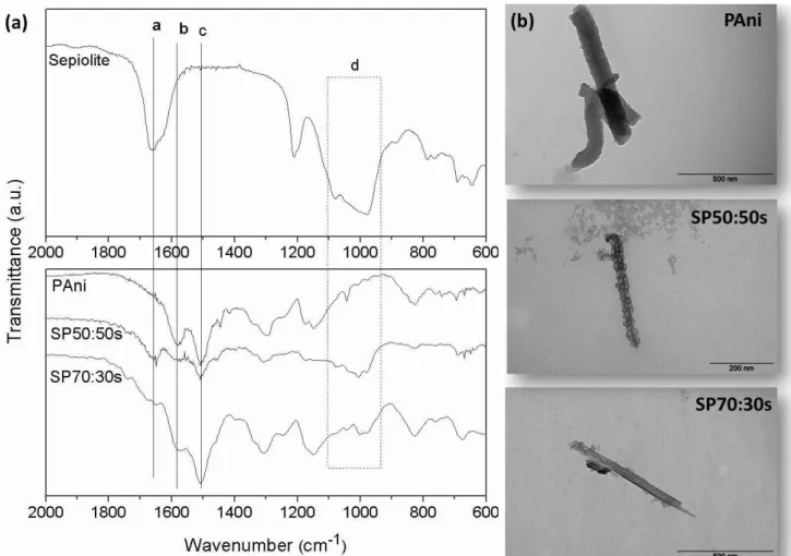
polyaniline. As indicated in the Table 1 the amount of polyaniline in the composite is very small when 10% of aniline is employed. Figure 3a shows the FTIR spectra of SP composites. The SP70:30s sample displays the band a at 1658 cm-1
and band d at 1000 cm-1 which are typical of sepiolite and the bands b and c at 1584 and 1497 cm-1 are ascribed to the
sepiolite indicates that the fiber was not completely coated by polyaniline. In the SP50:50s sample, the bands related to the sepiolite are not so evident indicating that the PAni coating was more effective. The images shown in Figure 3b corroborate the FTIR results. It is possible to see in the micrograph the presence of several nanoparticles of PAni well adhered to the sepiolite surface along all fiber surface. The amount of polyaniline in these composite was estimated by TGA analysis, and corresponds to 14 and 46 %wt. of PAni for the SP70:30s and SP50:50s samples, respectively.
Figure 3. FTIR spectra (a) of sepiolite, PAni, SP70:30s and SP50:50s and TEM micrographs (b) of PAni, SP50:50s and
SP70:30s by slurry polymerization
3.3 Electrorheological properties
Preliminary tests were performed to determine the electrorheological parameters. To measure the electrorheological properties an electric field (0.5 kV/mm) was applied at different frequencies (f) (10 Hz, 5 kHz and 15 kHz) and the current density was measured in each case. Based on the results indicated in the Table 2, at large frequencies the current density (j) was high and the shear stress small. For this reason, all measurements were performed at 10 Hz corresponding to the largest yield stress τy and the smallest current density and the electric field range was 0-2 kV/mm. Only the
SP50:50s sample was studied in detail and the polyaniline fibers were used for comparison, because, as presented in Table 2, the SP70:30s sample presented a yield stress three times lower than the SP50:50.
Table 2. Yield stress τy at different frequencies (f) at 0.5 kV/mm (AC)
Sample τy (Pa) j(µA/mm2) τy (Pa) j(µ A/mm2) τy (Pa) j(µ A/mm2)
10 Hz 5 kHz 15 kHz
PAni 36 9.9x10⁻³ 15 0.17 10 0.19
SP70:30s 67 6.5x10⁻³ 28 0.13 14 0.17
SP50:50s 192 4.7x10⁻³ 82 0.05 30 0.16
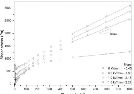
Figure 4 presents the curves in the control shear rate (CSR) mode for dispersions containing SP50:50s under different electric field strengths. This fluid was submitted to an AC (10 Hz) electric field (E) at 0, 0.5, 1 and 1.5 kV/mm and analyzed the dependence of shear stress with shear rate at room temperature, within the shear rate range of 0.001–1000 s−
1 Without an external electric field, the dispersions containing SP50:50s presented shear-thinning phenomenon. Similar
behavior was observed by J Yin et al[26] using fluids based on nano-fibrous PAni. Differently the composites with PAni/ClayMMT studied by Choi et al[8] with 20%wt and Lim et al [9] with 15% -wt presented a typical Newtonian behavior.
In the presence of an electric field the dispersions containing SP50:50s still presented the shear-thinning phenomenon but on a limited flow range, like plastic materials. The yield stress τy increases with E, from τy = 192 Pa at 0.5 kV/mm, to
τy = 400 Pa at 1 kV/mm and τy = 707 Pa. at 1.5 kV/mm. At high shear rates (500-1000 s-1) the slope of the flow curve
with applied field was observed to be much higher than that one in the absence of field. This last observation indicates that, unlike the prediction of the Bingham model, the stress needed to break the aggregates increases with the shear rate. This behavior may be attributed to the change of structure of these aggregates which becomes less compact and then occupy a larger effective volume fraction when the shear rate increases.
Figure 5 compares the dependence of the yield stress as a function of the applied electric field in log–log scale. The
yield stress (τ ) used in this plot was measured at 0.1 s-1, for the SP50:50s composite and PAni nanofiber suspensions.
The electrorheological response of the dispersion containing 50:50s and PAni fibers increases strongly with increasing electric field at low shear rate. The correlation of the yield stress and the electric field strength (E) can be represented as
[26-28]
τ
y∝
E
α
According to the literature, α = 2, corresponds to the polarization model and α equal 1.5 to the conduction model [29,
30] A linear relation between the yield stress τy and the electric field can be the signature of the polarization of polar
molecules at the surface of the particles, as found in the giant electrorheological effect [31]. This behavior is also often attributed to the saturation of the local electric field due to the exponential increase of conductivity in the gap between two particles [29, 32]. Tsuda et al. found a slope of 1.8 for spherical particles of aluminum-borate, but for whiskers of the same composition, the slope decreased to 1.3 [33]. Also, in the study reported by Cheng et al., they noted that the change of morphology of the TiO2 particles influence the structuring process under an electric field [6]. Yin et al. obtained the
range of α = 1.8-1.2 for the PAni fibers made with L-camphorsulfonic acid. And the authors observed a decreasing of the yield stress as a function of electrical field slope with increasing the acid concentration [26]. In this work both samples, SP50:50s and PAni, have a similar morphology and the same volume fraction, so a change of slope cannot be directly related to the change of morphology. Still the slopes are different with α=1.52 for PAni fiber, this correspond to the conduction model and α=1.24 for the polyaniline coated sepiolite (SP50:50s) indicating that the presence of insulated materials interfered in the conduction model for PAni.
Figure 5. Yield stress as a function of electric field at shear rate (0.1s-1) for SP50:50s and PAni suspensions at volume
fraction Φ=10%
The relative dielectric constant of SP50:50s particle was calculated by εparticle=1.5(εpellet -1) /φ, where εpellet is the
dielectric constant measured and φ is the volumetric fraction of particles in the pellet (φ = 0.65, volume particle/volume pellet). The absolute dielectric constant is defined as the product of the relative dielectric constant and dielectric constant in the vacuum, ε*= ε
r ε0. This relation is based on the Maxwel-Garnett theory for needle like particles, supposing an
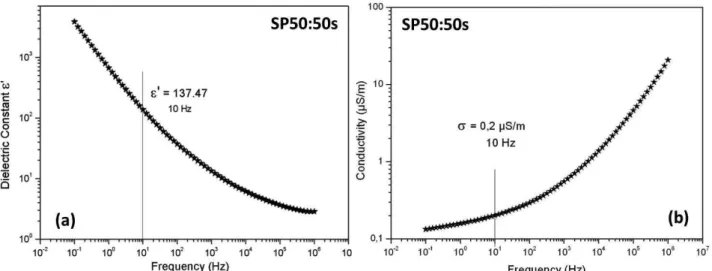
isotropic orientation of the needles inside the pellet. Figure 6 show the relative dielectric constant and conductivity as a function of frequency. The conductivity of the particles is roughly the one of the pellet divided by the volume fractions of the particles.
Figure 6. Relative dielectric constant (a) and conductivity (b) as a function of frequency obtained from SP50:50s pellet
with the correction of volume fraction
force F .In the linear polarization model the force between two dipoles aligned in the direction of the field and separated by a distance L is given by:
2 E 4 0 f
1
6m
F
4
L
=
πε ε
(1)with the dipolar moment of a fiber given by:
0 f 0
m
=
3V
β ε ε
E
(2)
where V=Lπd2/4 and β is a function of the permittivity and of the conductivity of the two components; for a fiber like
particle we obtained:
( )
(
)
2 2 2 0 p f 2 f z p z MW1
3(
(1 n )
n )
1
σ − σ
+ ωτ
β =
σ −
+ σ
+ ωτ
(3) With z f z p f 0 MW f z f z p(1 n )
n
and
(1 n )
n
−
ε + ε
ε
τ =
τ
=
σ
−
σ + σ
σp particle conductivity, σf fluid conductivity, εp absolute dielectric constant of particle, εf absolute dielectric
constant of fluid and ω the angular frequency. The depolarization factor along the main axis, nz, can be approximated by
the one of an ellipsoid:
z 2 2
1
1
n
1
arg cos h(r)
r
1
r
1
=
−
−
−
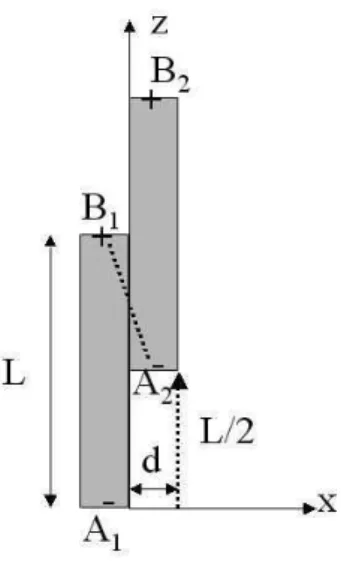
where r=L/d is the aspect ratio.Actually the Eq.(1) is not well adapted to fibers since it supposes that the dipoles are located at the center of the fiber whereas they are spread uniformly on the particle. A better approximation in this case is to consider the interaction between point charges located at the extremity of the fibers with an equivalent charge: Q=m/L where L is the length of the fiber [35]. The force between two fibers is attractive when the shift between their centers is larger than L/2 (cf. Figure 7). The main attractive force is the one between the charges located in the points B1 and A2, given by: F=Q2/(4πε0ε1r2). We
suppose that the fibers will slip along each other before to separate. At the end point the attractive force will be along the x axis and its magnitude will be:
2 E 2 2 0 f
1
m
1
F
4
L d
=
πε ε
(4)Figure 7. Model of interaction between two fibers
Expressing m from Eq.(2) we obtain the final form of the average force between two fibers: then,
2 2 2 E 0 f
9
F
d E
64
π
<
>=
ε ε β
(5)
where β2 is given by Eq. (3)
We note here that the force is just proportional to the square of the diameter of the fiber, whereas if we were using Eq. (1)-(2) we would get an extra factor 6(d/L)2, which would decrease a lot the estimation of the electric force.
The hydrodynamic force which will pulls apart the two fibers can be approximated by the friction
coefficient of a fiber times the difference of velocity,
∆ = γ
v
ɺ
L
. The friction coefficient, ξ, of a fiber in a transverse flow is given by Batchelor [36] : f4
L
l og(2L / d)
0.5
πη
ξ =
+
.The denominator being of order unity, the shear force is finally:
2
s f
F
≈ πη γ
4
ɺ
L
and the Mason number for fibersreads: 2 S f 2 2 E 0 f
F
256
L
Mn
F
9
E
d
η γ
=
=
ε ε β
ɺ
(6)where ηf is the viscosity of the suspending fluid, and εf the dielectric constant of the suspending fluid. [30, 34, 37] As
in Eq.(6) should be changed accordingly . In the calculation for SP50:50s sample was used ε0 =
8.85 x10⁻¹²,
ε
f
¿
= 3.8 ε0, εp= 137.47 ε0, σf= 10-10 S/m, σp = 0.2 S/m, and an aspect ratio r = L/ d = 25, these values
were measured at 10 Hz. Figure 8 shows the relative viscosity (η/ηf) as a function of Mason number for SP 50:50s
suspension at different electric fields.
Figure 8. Relative viscosity as a function of Mason number for SP50:50s suspension
The shape of the curve is like the one obtained in electrorheological fluids with spherical particles[38]: There is a roughly linear part between Mn=10-3 and Mn=1 and the nonlinear part at Mn>1 corresponds to the regime where the
shear force dominates the electric one.
Viscoelastic tests were performed through strain sweep at strain range 0.01-5% and angular frequency (20 rad.s-1).
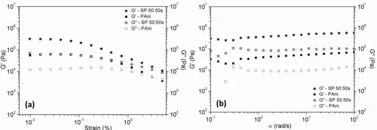
Figure 9a shows the storage modulus and the loss modulus as a function of strain for pure PAni and SP50:50s at a field E
= 2 kV/mm The fluid of PAni fibers presented a purely viscous behavior in the absence of an electric field, but the sepiolite coated by polyaniline (SP50:50s) presented a weak contribution (95 Pa) for the storage modulus in absence of field. Both samples (pure PAni and SP50:50s), in the presence of an electric field presented a solid viscoelastic behavior
with G’ larger than G”. The sample SP50:50s has a linear viscoelastic region smaller than pure PAni the region is 0.01 to 0.1% for pure PAni and 0.01 to 0.04% for SP50:50s but the magnitude of the field induced shear modulus is much larger for the SP50:50s sample.
Figure 9b represents the results, for fluids containing 10% vol. pure PAni fibers and SP50:50s, for a frequency (ω) sweep performed at 0.03% of strain, under electric field of 2kV/mm. Here too we see that under the same field, G’ of
SP50:50s fluid is an order of magnitude larger than G’ of pure PAni fluid. We note that for ω around 0.3 rad/s there is a small dip of G' and a maximum of G" for both compounds. This phenomenon is likely related to some structural relaxation time of the columns of fibers. Then there is a small increase of G' and G" with ω for the SP50:50 whereas it remains constant for the pure PAni sample. With the increase of field strength the values of the storage and loss modulus increase strongly. The slopes of G’ versus the electric field are given in the Table 3. It is noted that the slope of G' for the SP50:50s suspension was approximately the same as the slope of the yield stress versus field (1.24 compared to 1.28), but they are more different for the pure PAni suspension (1.32 compared to 1.52)
Figure 9. Storage Modulus, G’ and Loss Modulus, G” versus strain at ω=20 rad/s (a) and as a function frequency at 0.03% of strain (b) for PAni and SP 50:50s suspension at 2kV/mm,
Table 3. The storage modulus at different electric field
Electric Field PAni SP50:50s
E (kV/mm) G’(kPa) 0.0 0.01 0.08 0.5 9 117 1.0 23 202 1.5 37 352 2.0 56 536 Slope* 1.32 1.28
*The slope is obtained from the curve of the
storage modulus as a function of the applied electric field in log–log scale
4.
ConclusionThis work presented two different methods to prepare the polyaniline-coated sepiolite, denoted bulk and slurry polymerizations. The first method was effective for achieving good yield of polyaniline in all sepiolite /polyaniline compositions but resulted in the formation of aggregates of sepiolite embedded by polyaniline. Contrarily, the slurry polymerization of aniline in the presence of sepiolite gave rise to nice nanocomposites with PAni nanoparticles well adhered to the sepiolite surface. The composition to achieve the coating of sepiolite with polyaniline in larger extent corresponds to 46 -wt% of PAni, as indicated by FTIR and TEM and quantified by TGA analysis.
The best electrorheological response was obtained with suspensions of SP 50:50s sample, which contains sepiolite coated with 46 wt% of PAni. In fact, this suspension presented better ER effect than that constituted by pure PAni fibers, with a storage modulus, G’= 536 kPa for the composite SP50:50s and only 56 kPa for pure PAni fiber suspension at 2 kV/mm. These values are well above those published in previous papers for polyaniline based particles [39, 40]. The value of the yield stress of about 1 kPa at 2kV/mm for SP50:50s suspension is the same as the one obtained by Lim et al. [9] for a coating of PAni on montmorillonite clay platelets. We also note that an anisotropic shape (either needle or platelet) increases considerably the yield stress compared to spherical shape where a yield stress of about 300 Pa was obtained for the same field on a PAni coating of silica [11]. These results highlight the importance of developing hybrid polyaniline-based nanoparticles with elongated structures to obtain ER fluids with better performance and open new possibilities of synthesizing other hybrid materials with tuned morphology for electro-rheological fluids with better ER performance than those constituted by the pure components. In this context, the synthesis of other PAni- based materials with elongated structures and the evaluation of their ER performance are in progress and it will be subject of future publications.
Acknowledgments
This work was supported by Conselho Nacional de Desenvolvimento Científico e tecnológico - CNPq, Financiadora
de Estudos e Projetos - FINEP and Fundação de Amparo à Pesquisa do estado do Rio de Janeiro - FAPERJ. They also
thank S. Pergnotta (Centre Commun de Microscopie Appliquée, Université Nice-Sophia Antipolis) for her help with the electron microscopy.
References
[1] T. Hao, Electrorheological suspensions, Adv. Colloid Interface Sci. 97 (2002) 1-35.
[2] S. G. Kim et al., Emulsion polymerized polyaniline synthesized with dodecylbenzenesulfonic acid and its electrorheological characteristics: Temperature effect, Polymer 48 (2007) 6622-6631.
[3] C. Gehin et al., Electrorheological properties and microstructure of silica suspensions, J. Colloid Interface Sci. 273 (2004) 658-667.
[4] J. Jiang, Y. Tian, and Y. Meng, Structure Parameter of Electrorheological Fluids in Shear Flow, Langmuir 27 (2011) 5814-5823.
[5] Y. K. Kor, and H. See, The electrorheological response of elongated particles, Rheol. Acta 49 (2010) 741-756. [6] Q. Cheng et al., Synthesis and electrorheological characteristics of sea urchin-like TiO2 hollow spheres, Colloid
Polym. Sci. 289 (2011) 799-804.
[7] Y. D. Kim, and I. C. Song, Electrorheological and dielectric properties of polypyrrole dispersions, J. Mater. Sci. 37 (2002) 5051-5055.
[8] H. J. Choi et al., Synthesis and electrorheology of emulsion intercalated PAni-clay nanocomposite, Synth. Met. 121 (2001) 1325-1326.
[9] Y. T. Lim, J. H. Park, and O. O. Park, Improved electrorheological effect in polyaniline nanocomposite suspensions, J. Colloid Interface Sci. 245 (2002) 198-203.
[10] D. H. Song et al., Intercalated conducting polyaniline-clay nanocomposites and their electrical characteristics, J. Phy. Chem. Solids 69 (2008) 1383-1385.
electrorheology, Mater. Lett. 64 (2010) 154-156.
[12] Y. D. Liu et al., Fabrication of semiconducting polyaniline/nano-silica nanocomposite particles and their enhanced electrorheological and dielectric characteristics, Colloids and Surf. A 381 (2011) 17-22.
[13] Y. D. Liu et al., Smart monodisperse polystyrene/polyaniline core-shell structured hybrid microspheres fabricated by a controlled releasing technique and their electro-responsive characteristics, J. Mater. Chem. 21 (2011) 17396-17402.
[14] M. M. Ramos-Tejada et al., Electrorheology of suspensions of elongated goethite particles, J. Non-Newton. Fluid 159 (2009) 34-40.
[15] W. L. Zhang, and H. J. Choi, Fabrication of semiconducting polyaniline-wrapped halloysite nanotube composite and its electrorheology, Colloid Polym. Sci. 290 (2012) 1743-1748.
[16] M. Rautureau, and C. Tchoubar, Structural-analysis of sepiolite by selected area electron-diffraction - relations with physicochemical properties, Clays Clay Miner. 24 (1976) 43-49.
[17] C. Serna, J. L. Ahlrichs, and J. M. Serratosa, Folding in sepiolite crystals, Clays Clay Miner. 23 (1975) 452-457. [18] I. Bekri-Abbes, and E. Srasra, Characterization and AC conductivity of polyaniline-montmorillonite
nanocomposites synthesized by mechanical/chemical reaction, React. Funct. Polym. 70 (2010) 11-18.
[19] I. Bekri-Abbes, and E. Srasra, Solid-state synthesis and electrical properties of polyaniline/Cu-montmorillonite nanocomposite, Mater. Res. Bull. 45 (2010) 1941-1947.
[20] J. A. Marins, and B. G. Soares, A facile and inexpensive method for the preparation of conducting polyaniline– clay composite nanofibers, Synth. Met. 162 (2012) 2087–2094.
[21] Y. Yu et al., Polyimide/sepiolite nanocomposite films: Preparation, morphology and properties, Mater. Res. Bull. 46 (2011) 1593-1599.
[22] W. Hu et al., Flexible Electrically Conductive Nanocomposite Membrane Based on Bacterial Cellulose and Polyaniline, J. Phys. Chem. B 115 (2011)8453-8457
[23] E. Ruiz-Hitzky, Molecular access to intracrystalline tunnels of sepiolite, J. Mater. Chem., 11 (2001) 86-91. [24] J. A. Marins et al., Structure and properties of conducting bacterial cellulose-polyaniline nanocomposites,
Cellulose, 18 (2011) 1285-1294.
[25] C. G. Wu et al., Reaction of aniline with FeOCl - Formation and ordering of conducting polyaniline in a crystalline layered host, J. Am. Chem. Soc. 117 (1995) 9229-9242.
[26] J. B. Yin et al., Electrorheological fluids based on nano-fibrous polyaniline, Polymer 49 (2008) 4413-4419. [27] T. Tilki et al., Investigation of electrorheological properties of biodegradable modified cellulose/corn oil
suspensions, Carbohydr. Res. 345 (2010) 672-679.
[28] J. A. Marins, K. Dahmouche, and B. G. Soares, New electrorheological fluid obtained from mercaptosilsesquioxane-modified silicate suspensions, Mater. Sci. Eng. C 33 (2013) 133-139.
[29] Y. D. Liu et al., Conducting Material-incorporated Electrorheological Fluids: Core-shell Structured Spheres, Aust. J. Chem. 65 (2012) 1195-1202.
[30] C. W. Wu, and H. Conrad, Dielectric and conduction effects in non-Ohmic electrorheological fluids, Phys. Rev. E 56 (1997)5789–5797.
[31] S. H. Vemuri et al., New analysis of yield stress on giant electrorheological fluids, Colloid Polym. Sci. 290 (2012) 189-192.
[32] D. J. Klingenberg, F. Vanswol, and C. F. Zukoski, The small shear rate response of electrorheological suspensions .2. Extension beyond the point-dipole limit, J. Chem. Phys. 94 (1991) 6170-6178.
[33] K. Tsuda et al., Electrorheological behavior of whisker suspensions under oscillatory shear, Colloids and Surf. A 299 (2007) 262-267.
[34] L. Marshall, C. F. Zukoski, and J. W. Goodwin, Effects of electric-fields on the rheology of non-aqueous concentrated suspensions, J. Chem. Soc. Faraday Trans. 85 (1989)2785-2795.
[35] G. Bossis et al., Magnetorheology: Fluids, Structures and Rheology, Ferrofluids:Magnetically Controllable Fluids and Their Applications, Lecture Notes in Physics 594 S. Odenbach, Springer Berlin Heidelberg, 2003, pp. 202-230.
[36] G.K. Batchelor, Slender-body theory for particles of arbitrary cross-section in stokes flow, J. Fluid Mech. 44 (1970) 419-440.
[37] O. Volkova, S. Cutillas, and G. Bossis, Shear banded flows and nematic-to-isotropic transition in ER and MR fluids, Phys. Rev. Lett. 82 (1999) 233-236.
[38] M. Parthasarathy, and D. J. Klingenberg, Electrorheology: Mechanisms and models, Mater. Sci. Eng. R 17 (1996) 57-103.
[39] M. S. Cho et al., Synthesis and electrorheological characteristics of polyaniline-coated poly(methyl methacrylate) microsphere: Size effect, Langmuir 19 (2003)5875–5881.
[40] Y. D. Liu, F. F. Fang, and H. J. Choi, Core-Shell Structured Semiconducting PMMA/Polyaniline Snowman-like Anisotropic Microparticles and Their Electrorheology, Langmuir 26 (2010) 12849-12854.