Development of an Optimal Manufacturing Strategy
for Low-Volume Specialty Vehicles
By
Asoka Veeravagu
B.S. Applied Physics, State University of New York at Binghamton, 1993 Submitted to the Sloan School of Management
and the Department of Mechanical Engineering in Partial Fulfillment of the Requirements for the Degrees of
MASTER OF BUSINESS ADMINISTRATION
and
MASTER OF SCIENCE IN MECHANICAL ENGINEERING
In conjunction with the Leaders for Manufacturing Program at the
Massachusetts Institute of Technology
June 2002
C 2002 Massachusetts Institute of Technology. All rights reserved
Signature of Author:
''Sloan School of Management Department of Mechanical Engineering May 10, 2002
Certified by:
Professor Steven D. Eppinger, Thesis Advisor Professor of Management
Certified by:
Dr. Daniel 'Whitney, Thesis Advisor Senior Research Scientist
Accepted by:
Dr. Ain A. Sonin, Chairman, Department Committee on Graduate Students Department of Mechanicgl Engineering
Accepted by:
Margaret C. Andrews, Jxecdtive Director of Master's Program MIT Sloan School of Management
MASSACHUSETTS INSTITUTE
OF TECHNOLOGY
Development of an Optimal Manufacturing Strategy
for Low-Volume Specialty Vehicles
By
Asoka Veeravagu
Submitted to the Alfred P. Sloan School of Management and the Department of Mechanical Engineering
on May 10, 2002
in Partial Fulfillment of the Requirements for the Degrees of
Master of Business Administration
and
Master of Science in Mechanical Engineering
ABSTRACT
In recent years, the automotive industry has found it necessary to adjust its offerings to consumer desires that change more rapidly and are more varied than in the past. This factor, combined with an increase in worldwide competition, is requiring automotive companies to move faster in developing and producing new vehicles, and to be profitable at lower volumes per model. To address these issues, General Motors recently initiated the Halo program to quickly bring highly desirable show cars with innovative design concepts into production. The first of these vehicles is the Chevrolet Super Sports Roadster (SSR), a retro styled sport truck with a fully automatic retractable roof. The Halo Program calls for a unique new vehicle such as the SSR to be launched at regular intervals, up to a steady-state condition of multiple different Halo vehicles in production simultaneously. To maintain the strong appeal and high exclusivity of these vehicles, production volumes are limited to approximately
10,000 of each Halo model per year. In order to meet the business case for these highly
differentiated low-volume Halo vehicles, the manufacturing plan requires that GM implement
a batch build production strategy.
This thesis develops a batch build manufacturing strategy for the Halo vehicles based on overall program cost, material, labor and equipment changeover constraints. In addition to analyzing and developing the batch build factory changeover process, a mathematical linear program optimization model is created to optimize the lot size and changeover frequency of each Halo batch. The thesis concludes with strategic recommendations for the current SSR program as well as future Halo vehicle projects.
Thesis Advisors: Prof. Steven D. Eppinger, Sloan School of Management Dr. Daniel E. Whitney, MIT School of Engineering
ACKNOWLEDGMENTS
I wish to express my appreciation to the MIT Leaders for Manufacturing (LFM) Program for facilitating the opportunity to participate in the six and-one-half month fellowship at the host company. I was fortunate to have had the distinctive opportunity to develop both academically and professionally through cross-training in engineering, management and industrial business. I would also like to thank my fellow students in the LFM program for their friendship and support. I have learned a great deal from them as a result of the diverse backgrounds, individual talents and broad perspectives they bring to the program.
I would particularly like to thank General Motors (GM), the LFM partner company that
sponsored this research project. GM made me feel like an integral part of its team and allowed me to explore both its organizational structure and its technology, which provided a mutually beneficial learning experience. I specifically would like to recognize Ed Ivey, Tim
Lee, Bill Szkodzinski, and Greg Bellopatrick for all their advice and guidance during my internship. Additionally, I want to thank all my coworkers and friends on the internship: Mickey, Tim, Pat, Don, Cara, Bob M., Bill C., Dick, Andy, Bob W., Bill D., Glenn, Jerry, Linda, Denise, Mike and Evan.
I would also like to acknowledge my academic advisors, Professor Steven Eppinger and Dr.
Daniel Whitney, for their guidance throughout the internship and thesis process. They have provided valuable insight into the issues I investigated and I greatly value their ability to ask challenging questions and explore topics from a variety of perspectives.
I would like to thank my family, Mom and Dad, my brother Aijuna and my sister-in-law
Samantha for their support and guidance during the many years leading up to this thesis. Finally, I would like to express my deep gratitude to my wife-to-be Heather Linden, for the unconditional support sbe has given me since I set out on my LFM journey.
The author wishes to note that the host company edited the contents of this thesis for proprietary information
Table of Contents
LIST O F FIG U RES ... 7
LIST O F TABLES ... 7
LIST O F EQ UA TIO N S ... 7
Chapter 1 - Introduction... 8
1.1 Thesis Background ... 8
1.2 H istory of the H alo Vehicle Program ... 8
1.3 H alo Program Challenges... 11
1.4 Project Approach... 13
1.4.1 Project D evelopm ent and Definition... 13
1.5 Thesis Structure ... 14
1.5.1 M ethodology ... 14
1.5.2 M athem atical M odeling ... 17
1.6 Sum m ary ... 18
Chapter 2 - A nalysis of the Problem ... 19
2.1 Evaluation of Prospective Halo Vehicle Manufacturing Systems ... 19
2.1.1 Job Shop ... 20
2.1.2 M ixed Production... 21
2.1.3 Batch Build... 22
2.1.4 Comparison of Options and Determination of Halo Manufacturing System... 23
2.2 Batch Build Challenges and Solutions for Halo Vehicles... 25
2.2.1 Body-on-Frame vs. Body-Frame-Integral Processing Differences... 26
2.2.2 Tooling and Equipm ent Changeover... 30
2.2.3 M aterial Presentation and Changeover ... 38
2.2.4 Straggler Strategy... 40
2.2.5 Order to D elivery Requirem ents ... 41
2.3 Sum m ary ... 42
Chapter 3 - Batch Build Optimization Model Development ... 43
3.1 Utilization of M ath-Based Tools at G eneral M otors... 43
3.2 Optim ization M odel Driving Factors ... 43
3.3 M odel Scope... 45
3.4 Linear Program Optimization Modeling Approach and Algorithm... 46
3.5 M odeling Form ulation... 47
3.5.1 Inputs and Param eters ... 47
3.5.2 D ecision V ariables ... 48
3.5.3 Objective Function... 48
3.5.4 Constraints... 49
3.5.5 M odeling A ssum ptions ... 50
3.5.6 M odeling Optim ization Engine Required ... 51
3.7 M odel O utput ... 53
3.8 Scenario A nalysis... 55
3.9 Discrete Event Simulation Based on Model Output ... 59
3.10 M odeling Issues ... 63
3.11 Extensions to the Model... 65
3.12 Sum m ary ... 66
Chapter 4 - Socio-Technical Issues with Batch Building ... 67
4.1 Organizational and Cultural Issues with Batch Build Manufacturing ... 67
4.1.1 Effects of Learning as a Function of Elapsed Time Between Batch Runs ... 67
4.1.2 Modification of Workforce Job Responsibilities ... 71
4.1.3 Workforce Scheduling Policies as a Function of Batch Build Strategy ... 72
4.2 Summary of Chapter 4 ... 73
Chapter 5 - Conclusions ... 75
5.1 Summary of Recommended Batch Build Policies ... 75
5.1.1 Tooling and Equipment Changeover ... 75
5.1.2 Material Changeover... 76
5.1.3 Product and Process Complexity Reduction... 77
5.1.4 Readying the Workforce for Multiple Products... 78
5.2 Recommendations for Managerial Utilization of the Optimization Model...81
5.3 Further Considerations for Low Volume Niche Vehicle Manufacturing ... 82
5.4 C onclusions ... . 84
REFERENCES...85
Appendix A - Interview Process Guide... 88
Appendix B - Introduction to Linear Programming Optimization Methods...90
Appendix C - Equipment and Tooling Changeover Analysis ... 93
Appendix D - Halo Production Optimization Model...100
Figure 1-1. Figure 1-2. Figure 1-3. Figure 2-1. Figure 2-2. Figure 2-3. Figure 2-4. Figure 2-5. Figure 2-6. Figure 2-7. Figure 2-7. Figure 3-1. Figure 3-2. Figure 3-3. Figure 3-4. Figure 3-5. Figure 3-6. Figure 3-7. Figure 4-1. Figure 4-2. Figure 4-3. Figure 4-4. Figure B-1. Figure D- 1. Figure E-1.
M odel Scenarios for Evaluation... 55
Maximum Batch Size and Production Cost as a Function of Changeover Time . 57 Architecture Changeover Scenarios... 58
Scenario Results for Architectures with Varied Changeover Times ... 59
Model Objective Function... 48
Inventory Balance Constraints... 49
Production Resource Constraints...49
Set-Up Forcing Constraints...50
Non-Negative, Binary Set-up Variable Constraints... 50
LIST OF FIGURES
Chevrolet SSR Concept Sketch... 9SSR Show C ar ... 10
Project M ethodology... 15
Product-Process Comparison Matrix for Halo Manufacturing Options ... 24
Lansing Craft Center Sub-Factory Layout ... 26
Body-On-Fram e Architecture... 28
U nibody A rchitecture ... 29
Rolling Changeover Bubble ... 32
Single Spindle Tool Configuration on the Chassis Assembly Line ... 34
Tooling and Equipment Changeover Analysis Sample... 36
Batch Size and Cycle Frequency... 41
Batch Build Production and Changeover Plan - Unconstrained Case... 44
Batch Build Production and Changeover Plan - Constrained Case... 44
Production O utput M atrix... 54
Binary Set-up Matrix for Changeovers ... 55
Amount of Production Resources Needed Per Model Changeover ... 56
General Assembly Discrete Event Simulation Using ARENA... 61
Body Buffer Between Paint and General Assembly Factories ... 62
Production Loss as a Function of Batch Size ... 68
Effects of Learning and Forgetting on Performance Level... 69
BOF vs. BFI Staffing Requirements for Chassis Assembly ... 72
Chassis Line Staffing Level as a Function of Architecture ... 73
Simple Unconstrained Optimization... 90
Example Optimization Model with Four Time Periods ... 100
Sample Model Output for Reduced Inventory Holding Cost ... 101
LIST OF TABLES
Table 3-1. Table 3-2. Table 3-3. Table 3-4.LIST OF EQUATIONS
Equation 1. Equation 2. Equation 3. Equation 4. Equation 5.Chapter 1
-
Introduction
1.1 Thesis Background
The research for this thesis was conducted at the General Motors Technical Center in Warren, Michigan and at the General Motors Lansing Craft Center in Lansing, Michigan. The author spent six-and-one-half months on-site examining issues related to the manufacturing strategy for low-volume vehicle production.
1.2 History of the Halo Vehicle Program
For many years, General Motors (GM) has captured the automotive consumer's imagination with innovative, stylish, cutting-edge show cars. During the annual auto show circuit, a number of concept cars are displayed to the public for the purpose of creating excitement and demonstrating the design capability of GM. However, the automaker usually does not plan to put these unique vehicles into production. Most often, the concept cars are extremely expensive, one-of-a-kind fabrications produced for GM by a custom vehicle builder. The concepts do not in any way take into account the realities of actually developing or manufacturing the vehicle.
In mid-1999, the GM design group was again at work on a unique concept that would excite audiences around the world. This concept traces its lineage to the vision of the vice president of the GM design group, who challenged his staff to explore how a heritage design theme might manifest itself in a truck, vis-A-vis cars where retro designs abound. The executive director of GM's Brand Character Center then led the effort to develop potential options as to what this heritage truck might become. Both GM design executives wanted a heritage truck that was not simply a remake of a prior design, but rather, a modem interpretation of a classic theme. They wanted the concept to have clearly modem and aggressive styling, combined with readily identifiable heritage cues harking back to the famous Chevrolet trucks of decades past. This concept of blending the old with the new became known as "funkstalgia" within the GM design group.
While sketching potential concepts, one of GM's lead designers hit on a unique design that immediately caught the attention of the entire styling group. As seen in Figure 1-1, the basic sketch captures both modem and historical design cues such as large, sculpted fenders, a split-windshield and a multi-bar horizontal grill.
Figure 1-1. Chevrolet SSR Concept Sketch
This sketch was one of the few renderings of this concept to actually be put on paper. In August 1999, senior management reviewed the team's work and authorized the SSR be built for the 2000 auto show circuit. Designers developed the vehicle solely using math-based digital tools, in preparation for the January 2000 Detroit Show.
A few weeks after beginning work on the design, the concept was ready for virtual reality
design reviews. Up to this point, the concept was called the "Slammer", recognizing its
lowered-to-the-ground, or slammed, appearance. However, the concept's name was changed to Super Sports Roadster (SSR), an appellation combining the history and heritage of the "SS" designation with the open-air attractiveness of a roadster.
After favorable management review, a full-size mock-up of the concept was milled on a
CNC' machine directly from the digital styling data. This allowed extreme compression of
the concept design process, and by September 1999, the full-size model was shown to GM's North American Strategy Board (NASB), the group responsible for authorizing further development on vehicle programs. The Board was extremely impressed and enthusiastic
1 CNC is an acronym for "computer numerically nntrolled" and refers to the computerized method used to
about the concept, and challenged the design team to develop a running prototype in time for the January 2000 Detroit International Auto Show.
The challenge now became how to compress what would typically be one-year's worth of design and engineering effort into just a few months. Utilizing GM's internal resources, combined with efforts from a partner design supplier, the team met the challenge of the Board and brought a running show car to the Detroit Auto Show in January 2000. The culmination of the team's effort is seen in Figure 1-2.
Figure 1-2. SSR Show Car
The response of the public and the automotive press was overwhelmingly positive. GM
marketing and public relations groups received a deluge of inquiries concerning the SSR, asking when, if at all, GM would produce it. The company then surprised the automotive world in the spring of 2000, when the CEO announced that the SSR would be released as a production vehicle in late 2002.
General Motors' management deemed the SSR a worthy concept to bring to market because of its tremendous public appeal and the ability to use this one vehicle as a flagship for a GM division. The North American Strategy Board liked the idea of developing a unique model to represent each division and attract buyers to the brand. Furthermore, since the SSR concept was designed to be a viable option for production from the start, it could move rapidly into GM's future production plans. It was decided hat the Halo program would commence with the SSR and then launch a unique new vehicle derived from a high-visibility show car at
regular intervals. Thus the Halo program was initiated.
1.3 Halo Program Challenges
Due to the unique low-volume requirements of this specialty vehicle, a number of challenges arose for GM. With the kickoff of the Halo program, engineering and manufacturing teams worked feverishly to devise a plan to enable production of the SSR by late 2002. This plan needed to ascertain exactly how the SSR would be styled, engineered, prototyped, tested and manufactured in an accelerated timeframe.
Design and Engineering Challenges
The cycle time for a typical GM product development program currently takes approximately
36 months from the end of feasibility assessment to the start of production. In order to develop the SSR in time for a late 2002 launch, an even more aggressive schedule needed to be pursued. A financial and resource analysis was performed to evaluate the feasibility of producing the SSR via the traditional in-house GM Vehicle Development Process (VDP). The results of this analysis revealed that attempting to develop the SSR within GM could not be justified because of the high overhead costs that would need to be allocated over the low-volume program. Hence, there was no business case for maintaining the SSR in-house. At this point the SSR was turned over to the Specialty Vehicle Group (SVG) to evaluate alternate methods for producing the first Halo vehicle. After investigating various possibilities, the
SVG determined that partnering with an outside design and manufacturing firm could enable
Accordingly, GM partnered with an outside supplier to do a majority of the design and engineering work on the SSR. But with GM in charge of managing the program and the supplier-partner responsible for executing it, a number of new issues surfaced. For example,
does the supplier-partner, a company that has never previously engineered a full vehicle, have sufficient technical expertise to create the SSR? Additionally, by outsourcing the development functions of this program, does GM lengthen the chains of communication and
allow a greater possibility for design rework, thereby increasing its time-to-market?
Furthermore, does outsourcing full vehicle product development, a core competency for most
automotive original equipment manufacturers (OEMs), diminish GM's knowledge base and skills while enhancing the partner-supplier's technical expertise? How does this affect the long-term strategy of GM ifflagship vehicles must be engineered outside the mainstream of the company? These questions and others are being addressed as the Halo program progresses. This thesis does not focus on these product development issues, but instead addresses some of them at a fundamental level.
Manufacturing Challenges
Successfully tackling the challenges faced during the product development phase of the SSR is of extreme importance to he success of the Halo program as a whole. Equally important is effectively managing the manufacturing challenges faced by the program, since the overall business case is predicated on an optimized process for both development and manufacturing.
In order to profitably manufacture the low-volume Halo vehicles, GM needs to devise a manufacturing plan that permits highly differentiated products, based on varied product platforms and architectures, to all be manufactured on the same fixed production line. But a number of key questions arise. For example, what is the manufacturing strategy for
producing multiple vehicle models on the same line with a minimum of investment in new tooling and equipment? What are the manufacturing ramifications of designing and engineering a vehicle by a company not intimately familiar with the GM manufacturing systems? and What is the best way to balance and create product and process flexibility in the production system? Although the subsequent Halo vehicles are still a few years way, developing a strategy to manufacture them now is crucial since equipment and processes are
currently being designed and installed for the SSR. This thesis focuses on defining and addressing the manufacturing challenges faced by General Motors in bringing the Halo vehicle program to fruition.
1.4 Project Approach
As noted previously, the objective of this thesis is to investigate and develop a manufacturing strategy for the Halo vehicle program. In this section, the project development and definition, the project methodology, the modeling process, and the thesis structure are discussed.
1.4.1 Project Development and Definition
In the past, General Motors has been highly successful at running projects on a grand scale, but not as successful at maintaining a business case for low-volume niche programs.2 Much of this issue is due to the fact that the strategy for effectively producing large volumes of vehicles, using large factories with many machines and a large number of people, is not congruent with efficient low-volume automotive production. The Halo initiative is the first time General Motors is developing a manufacturing strategy dedicated to producing multiple low-volume vehicles in one plant. This program is unique in that it requires fundamentally new ways of looking at automotive manufacturing, and hence, of doing business.
The goal of this Leaders For Manufacturing internship and thesis is to help the General Motors SSR program management team devise a manufacturing strategy for multiple Halo vehicles, all manufactured on the same fixed line in the low-volume production facility. To help formulate this strategy, evaluation of relevant existing production systems is performed. Then, a station-by-station evaluation of the model changeover process in the factory is conducted. Finally, a mathematical optimization model of the manufacturing process is developed. This model will determine the optimal batch size and changeover frequency based on a number of constraining factors including changeover time between vehicles, order-to-delivery requirements, production learning curve after a changeover, acceptable inventory
2 Niche automotive programs design and manufacture vehicles in small quantities with the intention of catering to a highly specific segment of the market. GM's electric car, the EV-1, is an example of a niche automotive product.
levels, and other key constraints. The output of the model will assist the GM program management, production planning and manufacturing teams in determining the frequency and optimal lot size for producing each vehicle in order to best meet the Halo business case. Additionally, this thesis will provide strategic recommendations to future Halo vehicle teams to enable each new Halo vehicle to readily integrate with the developed batch build strategy.
1.5 Thesis Structure
This thesis is organized in a similar manner to the project timeline the investigator experienced on his internship. Chapter one provides background information and a description of the problem. Chapter two analyzes the low-volume manufacturing problem from a Halo program perspective and determines the appropriate production system to use. The chapter then discusses key challenges, formulates solutions and provides recommendations for the chosen type of manufacturing system. Chapter three develops the optimization model, establishes test scenarios and analyzes the model's output. Chapter four discusses a number of the organizational and cultural issues surrounding the proposed manufacturing strategy. Chapter five presents the conclusions, which includes a review of some of the more important findings of the thesis investigation. Lastly, recommendations are made for areas where further research and additional extensions to the model would be beneficial.
1.5.1 Methodology
Rather than being fully planned from the outset, the project methodology illustrated in Figure
1-3 helped develop the thesis topic over time. The fundamental question addressed in this thesis, what is the optimal manufacturing strategy for the Halo vehicles? led to additional questions such as, what does "optimal" actually mean for Halo manufacturing, what
parameters need to be optimized in the manufacturing system, and what are the required goals and constraints of the manufacturing system? The iterative steps shown in Figure 1-3
A number of informational interviews were conducted with a wide variety of subject-matter
experts to gather insights about GM's current manufacturing operations and the unique aspects of the SSR and the Halo manufacturing requirements. The respondents' backgrounds covered a broad spectrum of GM's overall operations, including product development, manufacturing engineering, validation, design staff, production planning, purchasing, and quality control. Regardless of their particular backgrounds, most respondents were highly receptive to thinking about new ways of manufacturing and readily offered their thoughts on the unique manufacturing process required for the SSR and future Halo vehicles.
Frame Project Outline Optimization Model
-interview
tie Experts ModelMath Model Testnmg
Refinement %Create Modeling Scenarios Develop Strategic Recommendations Figure 1-3. Project Methodology
The interviews varned greatly in length due to the individual respondent's background, level of involvement and familiarity with the Halo program. In general most of the interviews lasted from one to one-and-a-half hours. Most of the interviews were conducted one-on-one or in small groups of team members from a related functional discipline. Appendix A
-Interviewing Process Guide, provides examples of questions that were asked in the
interviews. In devising the interview structure, Metzler (1996) was consulted for guidance on the interview process.
A number of major factors that influence the overall Halo vehicle manufacturing strategy
emerged from the interview process. Many of these issues did not have clearly defined answers at the time, but instead were posed as questions for further investigation, as follows:
. Factory layout and design. How can the factory best be laid out to accommodate the
existing process flow, thereby minimizing the cost of re-tooling the plant, while permitting flexibility for new vehicles?
* Equipment and tooling flexibility and changeover. How can tooling that is low-cost,
highly flexible and accommodating of yet unknown products and vehicle architectures be
designed? How can the time required for the manufacturing system to changeover between vehicle models be minimized, while doing so at a reasonable cost?
. Material availability and changeover. How can the production, containerization, shipment, storage and presentation of subassemblies and components be optimized? How will the factory handle the material requirements for repaired vehicles that missed their original production batch?
. Workforce allocation and flexibility. How can the differences in labor hours required per
vehicle between different types of automotive models be accounted for?
" Batch size and batch cycle frequency determination. What is the ideal range of batch
sizes within which to build each Halo vehicle in order to satisfy customer demands, minimize production costs, and maximize profit of the Halo program? How frequently should a cycle of vehicle models be run in order to meet the Halo program requirements?
. Industry best practices. What are the industry-wide best practices for automotive batch
build manufacturing? How do other industries develop and maintain a successful business case for batch build manufacturing?
. Optimization of the entire manufacturing system. Instead of optimizing subsystems of the manufacturing system (e.g. cost or quality or delivery), how can the overall system be run in the most optimal manner? How should "optimal" really be defined?
As a result of the information acquired through the interviews, a mix of both tactical and strategic deliverables were decided upon to address the manufacturing strategy question. The tactical aspects focused on developing a changeover strategy for equipment, material and
labor in the production plant. The strategic section concentrated on developing a mathematical model to optimize batch build production lot sizes. Metcalf (2001) describes a methodology for mathematical model development and testing. This methodology is modified for the Halo vehicle thesis project as depicted in Figure 1-3. Efforts at interviewing and refining the project were iterative, as indicated by the double arrow in the figure. Correspondingly, efforts intensified in understanding and assessing the components and systems (product design, equipment, material, labor and scheduling) to be considered as part of this work. After commencing the interviews and gathering sufficient background details, the creation of the math model and associated scenarios to evaluate began. Scenario creation again was an iterative step with refining the model, as more was learned about the model by testing the various scenarios.
During the batch build the research phase, a thorough understanding was gained of existing knowledge that would help solve the tactical problem. The following questions were investigated. How do other manufacturers build niche vehicles? What is GM's high volume
manufacturing process? How is the high volume car assembly process defined? and What is different about niche product manufacturing? The goal of this research was to fully
understand the issues and to uncover any existing tools at GM, other auto companies and other industries that could be useful in solving the problem.
1.5.2 Mathematical Modeling
The value of mathematical modeling in this thesis is three-fold: 1) it provides a method for understanding the sensitivity of the Halo manufacturing system to various input parameters, 2) it generates batch size results to be fed into discrete event simulations for further analysis and 3) it determines the minimum production cost for specific manufacturing scenarios. The model is particularly useful because the constraining equations and input variables in the mathematical relationships are adjustable, thus providing the user with the ability to assess
various production scenarios. See Appendix B - Introduction to Linear Programming Optimization Methods for an overview of basic linear programming models.
1.6 Summary
This chapter considered the history and initiation of GM's Halo program. An introduction to both the product development and manufacturing challenges faced by the Halo program was provided. This set the stage for the developing and defining the thesis project. The approach and methodology employed to develop a batch build manufacturing strategy for the Halo vehicles was then outlined. Lastly, an introduction to the mathematical modeling used to evaluate various production parameters was described.
The following chapter presents a detailed analysis of the Halo vehicle batch build manufacturing challenges and formulates potential solutions to address those issues. The chapter focuses on the concerns surrounding equipment and tooling, material, and labor as they relate to developing a flexible, low-cost manufacturing system.
Chapter 2
-
Analysis of the Problem
2.1 Evaluation of Prospective Halo Vehicle Manufacturing Systems
Due to the cost constraints placed on the low-volume Halo program, the basic requirements of the manufacturing strategy are clear devise a highly flexible, low cost production system capable of handling multiple product platforms and architectures3 on a single fixed line. Further requirements that must be addressed by the manufacturing strategy include:
* Providing the manufacturing capability to quickly move a Halo concept from auto show to production.
. Manufacturing multiple highly differentiated Halo vehicles from varied architectures, with innovative design and engineering features on the same production line at steady state.
. Designing into the system the capability to produce yet undefined products and architectures.
. Manufacturing each model in low-volume (approximately 10,000 per year) with the flexibility to balance individual product volumes as required.4
. Utilizing existing facilities and tooling to minimize capital expenditure.
. Relying on a high subassembly content so as to minimize the use of production floor space and enable rapid completion of the vehicle on the main assembly line.
In order to meet these requirements, three different types of production systems were evaluated: job shop, mixed production and batch build. Each of these systems are now discussed and analyzed in detail in connection with the Halo program manufacturing requirements. Key aspects considered when evaluating the production systems for Halo automotive manufacturing are: 1) the number of vehicle types to be produced, 2) the production volume for each vehicle type, 3) the layout or arrangement of equipment and processes used to manufacture the vehicles and 4) the flow of material through the equipment
and processes.
3 The difference betweenplatform and architecture is described in Section 2.3.1 of this thesis.
4 This flexibility provides GM with the ability to tradeoff volumes between products, e.g. produce 15,000 SSRs
2.1.1 Job Shop
A job shop production system produces many different products in volumes ranging from one
to a few of each product. Because typically many different products are produced in very low volumes, the equipment and tooling are general purpose. A job shop does not utilize a high
level of automation, but instead relies heavily on skilled manual labor to manufacture its products. Work in process (WIP) in this type of system is high and delivery times can be long.
Few automotive manufacturers utilize job shop manufacturing to produce their vehicles because of the high cost and slow pace of production. Since this method of production is best suited to very low volume manufacturing, an example of automotive manufacturers that do employ such a production system are the makers of specialized showcars and automotive prototypes.
Low-volume auto builders such as these do not make use of an automated conveyor system or moving assembly line; instead each car is loaded onto a dolly5 and pushed by hand from one workstation to the next. A small team of skilled workers then spends multiple hours at their station performing the required assembly tasks. Unlike assembly performed on a high-volume assembly line, a moving conveyor does wut drive the pace of production in a job shop.
This type of job shop production requires a high labor content and a good deal of "finessing" to fit and adjust parts into position. This tweaking is necessary because the parts used in a job shop are not held to a tight tolerance due to the use of low-volume production tooling. For example, on a high-volume program a sheet metal bracket would be manufactured on an automated stamping press, while on a low-volume program that same part would be manually formd on a brake press. The low-volume, manual process causes greater variation in the output of the parts and therefore the vehicle is essentially handcrafted during the manufacturing and assembly process. Since each portion of the assembly can be verified and then rechecked, this manufacturing system can approach the quality output of a mass assembly procedure. However this quality parity is achieved at the expense of efficiency, cost and productivity.
2.1.2 Mixed Production
A mixed production automotive manufacturing environment is one where multiple models are
simultaneously run on a fixed production line. In this system, there is no need for planned production downtime to change over equipment or tooling between models. This capability is made possible because the equipment, material handling systems, and computer controls are
highly flexible, permitting the production of many different products on the same line. In the
automotive application of this system, one vehicle model can be mixed in between two vehicles of different models or styles. A high level of automation and expensive flexible
tooling are the primary enablers of mixed model automotive production. The automation is required to identify each model as it reaches the station, ensure that the proper components are available at that station, and then perform the appropriate manufacturing process on that specific vehicle. The flexible tooling ensures that vehicles of different models can be produced back-to-back with no changeover of the production line between model runs.
For example, in a mixed-production manufacturing environment, automation could be used to identify the model of vehicle that is approaching the windshield glass installation station. The automated system would then initiate the correct equipment program for that specific vehicle, apply a bead of sealant in the proper locations, then use a robotic arm to select the appropriate windshield glass from a material rack, and finally place the windshield in the specified location using the appropriate pressure and duration.
Another key enabler to mixed-model production is the use of a common vehicle platform for all vehicles running down the line, discussed in Section 2.3.1. Reuse of the basic vehicle frame hardware and its associated underbody tooling is usually the focus of the mixed production approach.
Very few automotive manufacturers employ a multi-model mixed production system on their high volume vehicle lines. One that does is Ford Motor Company's Wixom assembly plant, which produces the body-on-frame Crown Victoria and the body-frame-integral Lincoln LS sedan, utilizing a high level of automation to enable simultaneous production of both cars. These different vehicle types are discusses in detail in Section 2.2.1.
2.1.3 Batch Build
A batch build manufacturing system produces fewer product models in higher volumes than
the job shop production system. In the automotive case, batch building involves the scheduling and production of different vehicle models and architectures in planned quantities based on demand, cost of changeover, and plant capacity. Stated simply, batch building allows for the flexible use of a production facility to build multiple platforms on a single line. This is achieved by developing a production line that allows changeover of equipment, material and labor between batches of each product.
Honda uses a batch build manufacturing philosophy that accommodates a variety of vehicles within a specified range of manufacturing systems, denoted as small, medium or large. Honda emphasizes a "process driven product design" as a key enabler for its batch build manufacturing strategy. All products entering a batch build factory must comply with a rigid set of architectural constraints, common locating holes for underbody tooling transfer, part shingling, sequence of assembly, and station balanced work content.6 This high level of product discipline allows Honda to make a serious commitment to a manufacturing system that can aggressively batch build any product within that set of conditions (Scholl, 2001).
The batch system must establish a minimum batch quantity and maximum number of changeovers per unit time period based on the business plan and plant capacity constraints. These primary aspects of batch building fall under the larger category of production planning, which entails determining what to build, when to build it, and in what quantities to build it
(Miltenburg 1995). Production planning for batch building involves economies of scale with some type of production function expression. This occurs because there is a required set-up cost to initiate the production of a specific product. For example, initiating the production of an item might require a change in tools, dies, or materials. The setup could also require a change in the production control settings, like line speed or conveyor height, as well as an initial verification run to assure that the vehicle meets output quality specifications.
6 The shingling of components involves an assembly sequence where the order of parts installation is important
due to component overlap. For example, during body assembly an outer body panel must shingle over components that make up the inner body structure. Because of shingling, the assembly order of these parts cannot be interchanged.
2.1.4 Comparison of Options and Determination of Halo Manufacturing System
Evaluating the three production systems discussed, it is evident that with respect to the goals of the Halo program each system has its benefits and detriments. The product-process matrix in Figure 2-1 (adapted from Miltenburg, 1995) compares the three systems from the standpoint of layout and material flow, products and volumes, and manufacturing outputs. For illustrative purposes, the figure compares each of the three proposed systems against the baseline system of a minimal variety product line used in typical automotive plants. The figure compares the manufacturing output parameters of cost, delivery, quality, productivity, flexibility and innovativeness for all four systems. Here, it is important to differentiate between the definitions of flexibility and innovativeness: flexibility refers to the ability of a manufacturer to increase or decrease production of existing products, while innovativeness refers to the ability to produce new products.
Job shop manufacturing is not feasible on the Halo Program due to the high cost and low production output of such a system. As seen in Figure 21, a job shop production system is lacking in a number of key areas. Operating a job shop factory to meet the annual requirement of approximately 10,000 of each Halo vehicle would incur excessive labor costs. Such a production system would not take advantage of the work standardization and variation reduction benefits of mass production, resulting in a negative impact on quality. Furthermore, a job shop's productivity and delivery outputs are not sufficient for Halo program goals. For these reasons, developing a job shop production system was ruled out for the Halo program.
In a traditional high-volume mixed-model automotive program, significant expense is incurred in implementing highly flexible automation with the capability to easily accommodate multiple vehicle platforms in the manufacturing process. Figure 2-1 shows the weaknesses of the mixed-model production system for the Halo program. Since autonmtion capital costs must be amortized over a relatively small number of vehicles, it raises overall production costs. Additionally, the mixed-production system is inadequate for coping with the injection of brand new, possibly yet undefined, products into the system. Therefore, implementing a mixed production system was determined not to be a feasible manufacturing
Products and Volumes Manufacturing Parameters
Many product Many Several Multiple
models, products, products, products, Delivery Quality
Innovat-One or a few Low Moderate High iveness
of each volumes volumes volumes Cost Productivity exibili
Functional A layout, Flow varied
Cellular
layout,F
SFlow varies Batch .
. with products
Line Flow,
c Flow mostly Mixed
roduction
Minimal
Equipment Variety
paced line Productio
flow,
Flow rigid
Weak Strong
Figure 2-1. Product-Process Comparison Matrix for Halo Manufacturing Options
Observing the performance of the batch building system in Figure 21, it is evident that for the purpose of the Halo program, the batch build system provides the required flexibility and innovativeness, keeps capital investment to a minimum, provides sufficient capacity to meet delivery requirements, and can maintain high quality and productivity levels. For these reasons, the GM manufacturing, operations and program management teams chose a batch build manufacturing system as the production method for the Halo program.
Although the Halo program implemented a batch build manufacturing strategy, batch building is not being used at any other GM production facilities and therefore, internal benchmarking was not possible. Further investigation revealed that batch build manufacturing across vehicle architectures is very rare in the automotive industry and that GM's Halo strategy is essentially the first of its kind. A number of other industries do use batch build manufacturing effectively. In the consumer electronics industry for example, the manufacturers of products such as cellular phones and PDAs run many products down a single fixed line, with an equipment, material and labor changeover between models. This is accomplished by using
flexible tooling and equipment that can be rapidly converted from one product to another, and
by careful supply chain planning to ensure that the required material is on the line at the
appropriate instant. Manpower may also be reallocated from one station to another during the batch changeover if labor content varies between product models. Although these industries do utilize a batch build manufacturing strategy effectively, they are not faced with the same level of regulations and controls that constrain GM. For example, the stringent requirements of the Federal Motor Vehicle Safety Standards (FMVSS) impose constraints on the Halo production system that are not present in other industries that utilize batch building.7 These, and other concerns regarding the batch build Halo automotive production system are addressed in the subsequent sections of this thesis.
2.2 Batch Build Challenges and Solutions for Halo Vehicles
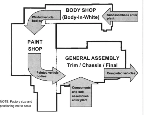
Although batch build manufacturing was determined to be the most feasible option for Halo vehicle production, a number of challenges need to be addressed before such a production system can be successfully implemented. The Halo vehicles will be manufactured in the Lansing Craft Center (LCC), an existing low-volume plant that currently produces the Cadillac Eldorado. The basic layout of the LCC is diagramed in Figure 2-2.
Kirsh (1994) summarizes the general layout and function of a typical high volume automotive plant. He describes the volume plant as consisting of the three main sections: the body shop (also referred to as body-in-white), the paint shop, and the general assembly area, which contains three secondary assembly processes (trim, chassis and final). The vehicle originates in the body shop where subassemblies and individual pieces of stamped sheet metal are welded and bonded together to fabricate the vehicle body. Next, the body moves into the paint shop where it is cleaned, electrostatically coated, primed, painted with a base coat and a top coat, and then baked in a paint-curing oven. The painted body then moves through the general assembly line where component-by-component, the entire vehicle is built into a final product. The LCC follows this general arrangement and functionality of the high volume plant, but with significantly less reliance on automated systems.
7 The Federal Motor Vehicle Safety Standards (FMVSS) are government imposed automotive regulations that
stipulate the minimum performance requirements for automotive crashworthiness. It is the manufacturer's responsibility to design, develop and manufacture vehicles that conform to these standards.
BODY SHOP A
Welded vah" (Bd-in-White) pl '"ant
PAINT SHOP
GENERAL ASSEMBLY
Trim /Chassis /Final |
and sub-assemblies
NOTE: Factory size and ant
positioning not to scale
Figure 2-2. Lansing Craft Center Sub-Factory Layout
To convert the LCC from a single-product factory to a multi-model batch production plant requires careful consideration of a number of important factors. These factors affecting the
feasibility of batch building at the LCC are discussed in the next section.
2.2.1 Body-on-Frame vs. Body-Frame-Integral Processing Differences
Attempting to produce different vehicle architectures on the same fixed line produces serious hurdles for the Halo manufacturing systems because of the inherent variation between products. Minisha (1999), in describing a hierarchy of automotive product variety, asserts that in the auto industry, the highest level at which product variety influences the production system is the platform. A platform refers to the engineering guts of the vehicle, such as the chassis, and is not readily apparent to consumers. With different exterior skins put on, the platform results in multiple models. At GM, the Chevrolet Trailblazer and the GMC Envoy are both SUV models derived from the same 4-wheel drive truck platform. Models sharing the same platform generally have the same wheelbase, but it is possible and increasingly
common to derive a stretch model with a longer wheelbase.8 GM's stretch wheelbase Trailblazer XL, which is derived from an extended-wheelbase truck platform, is an example of this. Finally, automakers often attach multiple nameplates to one model with its sheet metal skin basic intact and minor cladding and fascia changes. The Chevrolet Cavalier and Pontiac Sunfire are GM models that fit this category.
This author contends that for the Halo Program, the most important level of product variety to the manufacturing system is vehicle architecture, and differentiates between architecture and
platform. The author defines architecture as the type of chassis design around which the
vehicle is created, either a body-on-frame or a body-frame-integral design. GM produces a number of different vehicle platforms on different architectures, including a rear-wheel drive, body-frame-integral structure, and a 4-wheel drive body-on-frame structure. From a Halo vehicle manufacturing processing perspective, the most glaring difference between two vehicles lies in their architectures. This is because costly, highly specific tooling and equipment is required to locate and transport the different architectures throughout the factory, primarily in the body shop, where components must be held rigidly and precisely in place while they are welded into a structure. A comparison of the two architectures follows.
Body-On-Frame Architecture
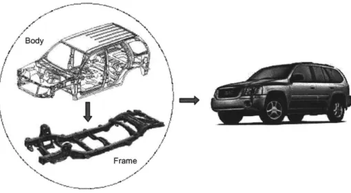
The body-on-frame (BOF) vehicle design has been in existence since nearly the birth of the automobile. This type of vehicle architecture utilizes a steel frame or chassis that is fabricated separately from the body of the vehicle. Using today's modem manufacturing processes, the steel frame is fabricated by a combination of hydroforming, welding and mechanical fastening, and is usually produced by a tier-one supplier.9 The unadorned frame is shipped from the supplier to the GM assembly factory where it is built up into a complete frame assembly including engine and transmission, steering and suspension components, wheels and tires, and other running gear. The completed frame is then transported within the factory to
8 Wheelbase is defined as the distance in inches (or millimeters) between the front and rear axles of an automotive vehicle.
9 Hydroforming is a process of shaping steel tubes through the application of water at extremely high pressure.
It replaces traditional stamping processes, preserving more of the steel's strength and stiffness as it goes through the forming process. It is performed at low temperatures to retain optimal nuterial properties, resulting in high strength and stiffness, relatively low weight, precise quality and reduced material usage.
the main assembly line where it is then mated to the body. An example of the BOF architecture is presented in Figure 2-3.
Body
*N, Frame
Figure 2-3. Body-On-Frame Architecture
Body-Frame-Integral Architecture
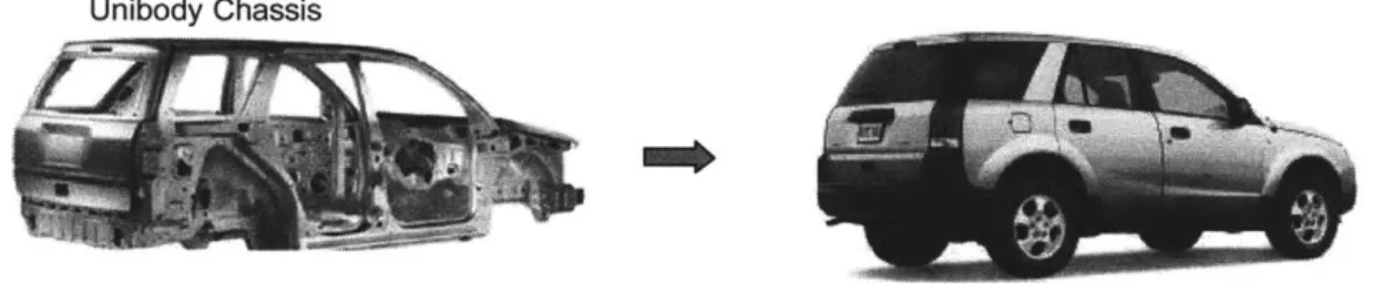
An alternative vehicle architecture is the body-frame-integral (BFI) structure, also referred to as a unibody (unitized-body) or spaceframe construction. With this architecture, the vehicle's structural rigidity is derived from the overall spaceframe - a combination of primarily steel and select aluminum components welded and bonded together. In this case, the drivetrain, suspension and other running gear are attached directly to the unibody, there being no separate frame. Since the structure of the vehicle is provided only by the strength of the welded components, accurately locating the unibody components with respect to each other during processing through the body shop is crucial. A completely welded unibody chassis
before and after final assembly is shown in Figure 2-4.
The processing differences between the BOF and BFI architectures lead to the potential that some manufacturing processes in the LCC cannot be performed in the same order. For example, since the SSR is a body-on-frame design, its fuel tank is loaded and secured to the frame on the frame subassembly line. Alternatively, the second Halo vehicle at the LCC may likely be a unibody design, where the fuel tank is loaded from beneath the chassis while the
vehicle is suspended on the main assembly line. The deviation from a common manufacturing process leads to additional complexity in the factory. This is due in part to the duplicate tooling necessary to perform the same assembly task, and because operators working at a fixed position on the line now have different tasks to perform depending on the model running down the line. Furthermore, due to constraints of shingling components described in Section 2.1.3, it is not possible to simply move the installation of certain components to another location on the line. Since the Halo program desires to produce vehicles from different architectures on the same production line at the Lansing Craft Center, successfully addressing this processing variation is of primary concern.
Unibody Chassis
Figure 2-4. Unibody Architecture
Product Development Recommendations for Handling Multiple Vehicle Architectures
Although running multiple product architectures and platforms on the same line poses a serious challenge for the Halo program, a number of product development options are available to handle this production requirement, as follows.
Design products to the Halo "box" requirement - Any Halo vehicle design should fit within the maximum cubic space or volume defined by the factory's constraints. If
manufacturing engineering can develop tools and equipment to accommodate any type of vehicle within this box, it will enable the Halo product development teams to have a range of flexibility for their product designs within this overall size envelope. Designing a vehicle outside of this acceptable volume means the vehicle may not be able to be produced at the LCC. For example, in the paint shop, phosphate dip tanks are capable of
fully submerging a vehicle of a certain maximum size. Designing a vehicle any larger than these established dimensions would render it unproduceable in the LCC.
" Product designs should have no body shop options - Since expensive, and often times
unique, weld guns and locating hardware are required to handle product options in the body shop, eliminating body shop options minimizes unique tooling poliferation.10
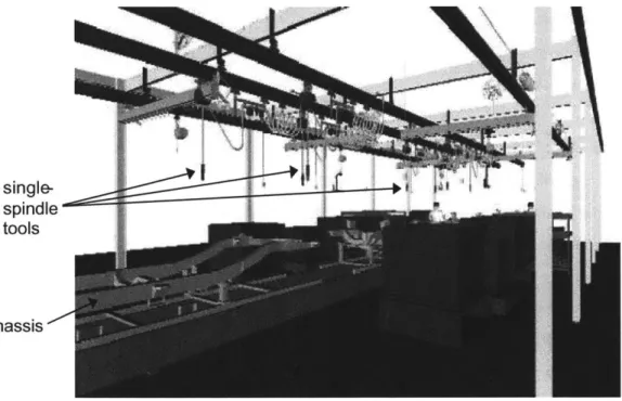
" Utilize common product hardware across model designs - Attempting to minimize variations between models by commonizing components will help reduce the number of unique tools needed in the factory. This complexity reduction is particularly critical in the general assembly factory, where differences in vehicle architecture (car vs. truck) force the need for multiple, unique single-spindle tools to drive and secure all fasteners.1 Areas that should be considered for commonality include: 1) subassembly module and piece part component reuse across platforms or architectures, 2) shared fasteners and torques where possible, and 3) common location points for installation of components and subassemblies.
2.2.2 Tooling and Equipment Changeover
Changeover Tactics
It was initially thought that for the tooling and equipment changeover strategy, it might be possible to convert over the hardware in all three sub-factories at the same instant in time. This would have enabled all processes within the LCC to switch over and process the same vehicle model simultaneously. However, it quickly became evident that this strategy would not be feasible. Since the automotive production line used in the LCC is a moving conveyor system inherited from the existing plant, a simultaneous changeover presents two options: 1) stop the entire conveyor at one time, purge all the existing work on the conveyor, and replace it with another model and 2) wait until the last unit of a specific model has worked its way through the entire manufacturing process, next changeover all the equipment, and then begin production of a new model. Both options are infeasible because there is insufficient factory floor space at the LCC to pull vehicles off the line and store them, and waiting until the last
10 Body shop options use different metal components and weld equipment to fabricate products with a unique dimensions or features. Examples of body shop options are a trunk versus a hatchback model.
" Single spindle tools are hand-held pneumatic or electrical nut-runners (also referred to as nut-drivers) used by production operators to drive mechanical fasteners (e.g. nuts and bolts) to a specified torque.
vehicle is completely processed would accrue an inordinate amount of idle time from stations upstream that are waiting to changeover.
Recognizing that a concurrent changeover plan was not viable, the revised mainstream direction established for the Halo program was to changeover all of the equipment and tooling in the factory in a rolling "changeover bubble". This means that when the last vehicle in a batch of one model leaves a station, the next arriving skid is empty and the qperator utilizes the non-production time to switch over the equipment at his or her station. The initial target established by the batch build strategy team for the duration of this changeover bubble was 30 minutes. This baseline target is the maximum amunt of time permissible to maintain the factory's required production capacity for the planned demand. A changeover bubble greater that 30 minutes will not allow the factory to meet annual demand requirements.
The main changeover bottleneck driving the estimated 30-minute time are the framer gates in the body shop - large pieces of complex welding equipment that must be manually changed and set-up for each model. Although this is an issue, the framer bottleneck can be buffered or the body shop line can be run at over speed to compensate for the 30-minute downtime. However, from the standpoint of the overall manufacturing strategy, the area of the production process that matters most is the final area of the general assembly factory. In this area, completed vehicles are shipped out of the plant. Therefore, any downtime in the final area affects actual factory output and hence, revenue generated by the plant.
With an expected line cycle time of approximately six minutes per station, a 30-minute rolling bubble means that five empty skids will pass through the station during the changeover window.12 This equates to a loss of five vehicles per station for each model changeover when the bubble passes through the factory, as seen in Figure 2-5.
12 This six minute cycle time was derived from the requirement to be able to produce 16,480 Halo units annually on one shift. The number of jobs per hours is: 16,480 jobs l year X Iday 9.7 jobs year 235 production days 7.23 work hours hour which translates to a cycle time of: 60 minutes I hour 6.2 minutes
Halo 1 Production
Trim
Lin-Halo 2 Production
Figure 2-5. Rolling Changeover Bubble
The batch build manufacturing system will be highly sensitive to overall changeover time of the system. A major driving factor to the system changeover time is the tooling changeover time, e.g., the time required to switch all the equipment and processes from one vehicle and set them up to run an alternate model. Obviously, the longer this equipment changeover time, the greater the cost of factory downtime and hence, the less efficient the overall system as measured by hours per vehicle, plant capacity and retum on investment.
A primary aspect of this thesis project involves analyzing the changeover process for the
entire production system at the LCC in order to evaluate methods for reducing the changeover time required between model runs. As part of a batch build strategy team, the author was
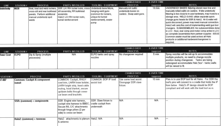
charged with performing a tooling and equipment monument changeover analysis at each station in the vehicle production process flow.13 These activities included the following:
13 A "tooling monument" refers to a large, fixed piece of tooling that is not easily transported from one location to another within the factory.