HAL Id: hal-01927378
https://hal.archives-ouvertes.fr/hal-01927378
Submitted on 19 Nov 2018
HAL is a multi-disciplinary open access
archive for the deposit and dissemination of
sci-entific research documents, whether they are
pub-lished or not. The documents may come from
teaching and research institutions in France or
abroad, or from public or private research centers.
L’archive ouverte pluridisciplinaire HAL, est
destinée au dépôt et à la diffusion de documents
scientifiques de niveau recherche, publiés ou non,
émanant des établissements d’enseignement et de
recherche français ou étrangers, des laboratoires
publics ou privés.
. Digital Holographic Microscopy With High Numerical
Aperture: Wide z Range Reconstruction
Nicolas Verrier, Dario Donnarumma, Daniel Alexandre, Gilles Tessier, Michel
Gross
To cite this version:
Nicolas Verrier, Dario Donnarumma, Daniel Alexandre, Gilles Tessier, Michel Gross. . Digital
Holo-graphic Microscopy With High Numerical Aperture: Wide z Range Reconstruction. Digital
Hologra-phy and Three-Dimensional Imaging 2016, Jun 2016, Heidelberg, Germany. �hal-01927378�
Digital holographic microscopy with high
numerical aperture: wide z range reconstruction
Nicolas Verrier1,2, Dario Donnarumma1, Daniel Alexandre1, Gilles Tessier3, Michel Gross1
1Laboratoire Charles Coulomb, UMR 5221 CNRS-UM2, Universit´e Montpellier Place Eug`ene Bataillon, F-34095
Montpellier, France
2Univ Lyon, Univ Lyon1, Ens de Lyon, CNRS, Centre de Recherche Astrophysique de Lyon UMR5574, F-69230,
Saint-Genis-Laval, France
3Neurophotonics Laboratory, CNRS UMR 8250, Universit´e Paris Descartes, Sorbonne Paris Cit´e, F-75006 Paris,
France
Abstract: A holographic microscopy algorithm is proposed enabling to deal with high numerical aperture holograms. Hologram reconstruction kernel performs under afocal condi-tions, which allows keeping the full NA over wide defocus range.
OCIS codes: 090.1995, 100.3010, 110.0180.
CitationNicolas Verrier, Dario Donnarumma, Daniel Alexandre, Gilles Tessier and Michel Gross. Digital Holo-graphic Microscopy With High Numerical Aperture: Wide z Range Reconstruction. in Imaging and Applied Optics
2016, OSA Technical Digest (online) (Optical Society of America, 2016),
Conference Digital Holography and Three-Dimensional Imaging 2016Heidelberg Germany 25–28 July 2016
1. Introduction
Digital holography aims at recording, on a CCD or CMOS sensor, the interference pattern between an object field wavefront (amplitude and phase of the wave scattered by the investigated object) and a reference wavefront. Three dimensional information about the investigated scene is further retrieved considering light back-propagation tech-niques [1]. Methods have been proposed for the specific case of digital holographic microscopy [2, 3], but these allow optimal amplitude and phase reconstruction only in the plane where the correction is calculated. These are therefore limited to 2D samples. Recently, we proposed a reconstruction method allowing a distortion-less reconstruction in both object and image half spaces [4]. In the following, we discuss of its extension to high numerical aperture (NA up to 1.4) [5].
2. Principles of the holographic reconstruction with high numerical aperture objectives
Fig. 1. (Color online) Typical holographic microscopy set-up for (a) recording, (b) reconstructing. BS1 and BS2, beam splitters. C, P, and U respectively denote the camera, the pupil (optimal plane of the MO), and the USAF image planes. The “X′” planes are the images of the aforemensioned planes through the MO.
The arrangement for high NA holographic reconstruction is proposed Fig. 1. It consists of a classical off-axis holography arrangement with an immersion Microscope Objective (MO). In classical microscopic imaging, both the object and the sensor have to be positioned in the optimal planes of the objective, i.e. planes P and P′(see Fig.1for details). As a matter of fact, these planes are, by design, the ones for which the optical aberrations are minimal. Thus, optimal imaging is achieved when camera planes (C and C′), object planes (U and U′), and optimal planes (P and P′) coincides (U = P = C and U′= P′= C′). Holographic imaging is less restrictive and only needs the object to be in the optimal plane to optimally operate (U = P and U′= P′). Indeed, the field in the camera plane (C̸= U) can be digitally propagated from camera C to optimal plane U = P by using standard reconstruction method with quadratic kernel. We propose here to go further and to conserve optimal resolution for an object not located in the optimal plane i.e. U′̸= P′ [5].
The proposed method, which apply for high NA hologram reconstruction, is composed of two main steps:
1. Field reconstruction (with a quadratic kernel) in the optimal plane P′that allows retrieving the corrected ampli-tude and phase in plane.
2. Field propagation from P′to U′. The complete propagation kernel has to be used to account for the immersion medium and the large illumination angles.
We also need to have a precise knowledge of the location of the optimal plane P′, the phase correction to be applied in plane P′, and the imaging magnification G of the optical system, which can be obtained by imaging a calibrated object such as an USAF target, to operate under optimal conditions.
3. Optimal holographic reconstruction
Fig. 2. (Color online) Principles of reconstruction. (a) Hologram HC(carrier fringes shown in inset).
(b) Hologram ˜H2 for dkx= dky= 0(in arbitrary log scale). (c) Hologram ˜H3 (details about the
filtering are in the main text. (d) Hologram H3reconstructed phase is associated with the RGB LUT.
The hologram recorded in the camera plane C is given by
HC=|E + ER|2=|E|2+|ER|2+ EER∗+ E∗ER, (1)
where E and ERare both the signal and reference field in the camera plane C. Here, two cases have to be distinguished:
the object is in optimal plane P′or the object is outside P′. The hologram HP′ in plane P′can be calculated considering
the method proposed in [4]. We here recall the main aspects of this procedure, which are illustrated by Fig.2.
3.1. Reconstruction for U′= P′
The first step of the reconstruction consists in multiplying the hologram HC(see Fig.2(a)) by a complex matrix CRM
hologram H1can therefore be calculated considering
H1(x, y) = HC(x, y)CRM= HC(x, y)ejk(x
2+y2)/2r′
ej(dkxx+dkyy). (2)
The MO-induced wave front curvature is considered as a second step. This is done by multiplying hologram H1by a
numerical lens (NL) CNLlocated in the camera plane C. The hologram H2is such that
H2(x, y) = H1(x, y)CNL(x, y) = H1(x, y) e− jk(x
2+y2)/2r
, (3)
where r is the focal of the NL that is adjusted such as the MO+NL optical system is afocal. FFT of H2, denoted ˜H2is
proposed Fig.2(b) for dkx= dky= 0. From ˜H2the selection of the +1 grating order is performed by applying a circle
crop of radius kmaxand adjusting dkx,yto bring the +1 order in the center of the k space. This consists of the hologram
˜
H3 illustrated Fig.2(c) and obtained with dkx= 255, dky=−244.52, and kmax= 162 pixels. Finally, as shown in
Ref. [5], knowing the optical magnification G makes it possible to reconstruct the hologram HP′from ˜H3by
HP′ ( x/G, y/G, z′P′)= FFT−1 [ ej(G2k2x+G2k2y)z′P′/2kmH˜3(Gkx, Gky) ] , (4)
where km= nmk is the wave vector in oil. This result is proposed Fig.2(d).
3.2. Reconstruction for U′̸= P′
The hologram HU′ in the plane U′can be obtained from hologram HP′ (see the derivations in the previous section and in Refs. [4, 5]). However, the propagation between U′and P′occurs in the oil, and numerical apertures can be large. It is therefore mandatory to deal with this propagation using the exact propagation kernel e− jk′zz′. Here k′
zis defined as
k′z= √
k2
m− k′2x − k′2y , where km= nm2π/λ, and kx,y′ = Gkx,y. The hologram in the plane is is finally given by
HU′(x′, y′, z′)= FFT−1 [ ejk′z(z′−z′p)FFT[H P′ ( x′, y′, z′P′)]]. (5)
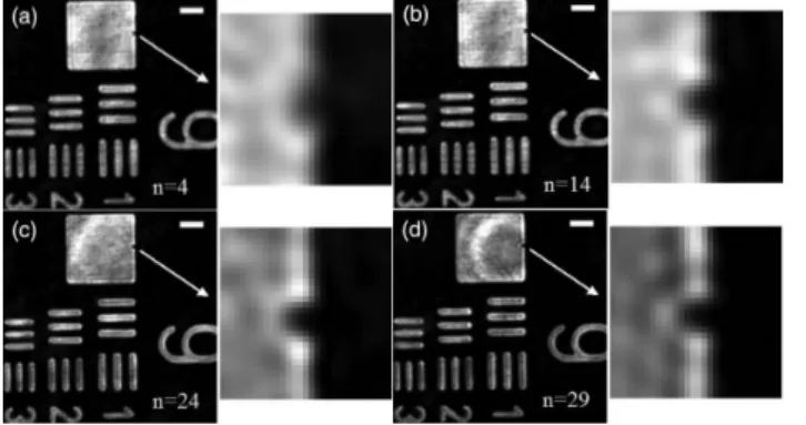
Illustration of the method benefits is provided by Fig.3. Here from the optimal hologram Fig.3(d), on can realize
Fig. 3. Reconstruction of high NA holograms for various defocus. (a) z′− z′p=−47.69µm. (b)
z′− z′p=−23.39µm. (c) z′− z′p= 0.8µm. (d) z′− z′p= 12.84µm. Scale bar is 3µm.
that our method allow to keep a good resolution with defocus up to−50µm. The same result is obtained for positive defocus but is not represented here. Therefore we are possible to keep an high resolution reconstruction over a large defocus range.
4. Conclusion
We proposed a two step reconstruction method operating with high numerical aperture holograms (up to NA = 1.4). The benefits of the methods have been demonstrated through the reconstruction of holograms recorded with a×60 NA = 1.4 oil immersion MO, proving the ability to keep almost full resolution in a [−50µm; 50µm] defocus range.
This work has benefited from a French State grant managed by the French National Research Agency under an Investments for the Future program (reference n.ANR-10-LABX-20).
References
1. U. Schnars, and W. Juptner, “Direct recording of holograms by a CCD target and numerical reconstruction,” Appl. Opt. 33, 179–181 (1994).
2. P. Ferraro, S. De Nicola, A. Finizio, G. Coppola, S. Grilli, C. Magro, and G. Pierattini, “Compensation of the inherent wave front curvature in digital holographic coherent microscopy for quantitative phase-contrast imaging,” Appl. Opt. 42, 1938–1946 (2003).
3. T. Colomb, E. Cuche, F. Charri`ere, J. Kuhn, N. Aspert, F. Montfort, P. Marquet, and C. Depeursinge, “Automatic procedure for aberration compensation in digital holographic microscopy and applications to specimen shape compensation,” Appl. Opt. 45, 851–863 (2006).
4. N. Verrier, D. Alexandre, G. Tessier, and M. Gross, “Holographic microscopy reconstruction in both object and image half-spaces with an undistorted three-dimensional grid,” Appl. Opt. 54, 4672–4677 (2015).
5. N. Verrier, D. Donnarumma, G. Tessier, and M. Gross, “High numerical aperture holographic microscopy re-construction with extended z range,” Appl. Opt. 54, 9540–9547 (2015).