HAL Id: hal-00818517
https://hal.archives-ouvertes.fr/hal-00818517
Submitted on 27 Apr 2013
HAL is a multi-disciplinary open access
archive for the deposit and dissemination of
sci-entific research documents, whether they are
pub-lished or not. The documents may come from
teaching and research institutions in France or
abroad, or from public or private research centers.
L’archive ouverte pluridisciplinaire HAL, est
destinée au dépôt et à la diffusion de documents
scientifiques de niveau recherche, publiés ou non,
émanant des établissements d’enseignement et de
recherche français ou étrangers, des laboratoires
publics ou privés.
Specification of a Collision-Free CSMA MAC Protocol
for Wireless LANs: the CANlike protocol
Guy Juanole, Xuan Hung Nguyen, Gérard Mouney
To cite this version:
Guy Juanole, Xuan Hung Nguyen, Gérard Mouney. Specification of a Collision-Free CSMA MAC
Protocol for Wireless LANs: the CANlike protocol. SaCoNeT 2013 - The 4th International Conference
on Smart Communications in Network Technologies, Jun 2013, Paris, France. pp.5. �hal-00818517�
Specification of a Collision-Free CSMA MAC
Protocol for Wireless LANs: the CANlike protocol
Guy Juanole
1,2, Xuan Hung Nguyen
1,2, Gérard Mouney
1,21
CNRS, LAAS, 7 avenue du Colonel Roche, F-31400 Toulouse, FRANCE
2Univ de Toulouse, UPS, LAAS, F-31400 Toulouse, FRANCE
juanole@laas.fr, xhnguyen@laas.fr, mouney@laas.fr
Abstract—Collision-free Medium Access Control (MAC) pro-tocols based on Carrier Sense Multiple Access (CSMA) and priorities associated to the frames are interesting solutions in considering real-time traffic in a wireless context. We have already presented such a protocol using priorities represented by the BlackBurst technique [1]. The goal of this paper is, at first and mainly, to specify another such protocol, named CANlike, which is an adaptation of the wired CAN bus protocol to the wireless context, and then to show its interest for the implementation of process control applications through a wireless network.
I. INTRODUCTION
Wireless networks and, more particularly, Wireless LANs are more and more used today in the industrial area where we have real-time applications which require Quality of Service (QoS) guarantees. In this context, the MAC protocols which implement the scheduling of the frames on a shared radio channel have an essential role.
Two main types of MAC protocols are TDMA (Time Division Multiple Access) and CSMA (Carrier Sense Multiple Access). CSMA is a totally distributed procedure whereas TDMA requires some centralized schemes. Then, CSMA is more flexible than TDMA with respect to changes in a network (adding or withdrawing stations and/or applications). Furthermore, CSMA is more suitable for sporadic traffic. In this work, we consider MAC protocols of the type CSMA for single-channel and single-hop WLANs (i.e. each node is in the transmission range of the other nodes, we do not have the hidden terminal and exposed terminal problems).
The main MAC protocol used in WLANs and based on CSMA is IEEE 802.11-DCF [2] (DIFS, Backoff, CW (Con-tention Window)) which does not support packet priorities and traffic differentiations. Another main one supporting packet priorities is IEEE 802.11e EDCA [3] (AIFSs, Backoff, CW) which allows traffic differentiations (by means of different AIFSs which expresses priorities represented by different time-outs). Some others in which the priorities are defined based on different sizes of Inter frame spaces, CW and Backoff are [4]. However, the big drawback of these protocols is that collisions can always occur due to the asynchronism between the transmission needs and the random behavior of the Backoff mechanism.
Obtaining collision-free CSMA MAC protocols and the QoS guarantees is possible by associating priorities represented by messages preceding the frames. The first approach is to use the BlackBurst technique [5], [6]. The idea is to let contending nodes send first jamming signals (called BlackBurst (BB)
messages) of length according to the priority. The node that has the longest signal (i.e. the highest priority) wins the competition and then sends its frame. The drawback of this technique is that if we have a great priority number, the jamming signals will be very long and give important delays. The second approach is to adapt the MAC protocol of the wired CAN bus [7] (the priority of the frame is expressed by the ID field which precedes the data field) to the wireless context [8]. This protocol is named CANlike. This paper is concerned by an exhaustive presentation of this protocol.
This paper includes the following sections: the section 2 concerns preliminaries which are necessary to well understand and specify the complete problematic; the section 3 presents the specification of the CANlike protocol; the section 4 con-cerns the conclusion.
II. PRELIMINARIES
We present knowledges concerning the physical (PHY) and MAC layers which are absolutely essential for the specification of the CANlike protocol.
A. Wireless transceiver
In a wireless context (contrarily to the wired context), a transceiver cannot simultaneously send and receive on a channel and has three states: Transmitter, Receiver, Sleeper. Here we do not consider the state “sleeper” which is used for considerations of energy economy.
Two time attributes characterize the transceiver behavior: the channel Sensing Time τST and the Turnaround Time τT T.
τST allows the transceiver to test the channel state (busy or idle): it is busy or idle depending on the detected energy on τST which is higher or lower than a prefixed threshold (this
represents the “Clear Channel Assessment” (CCA)). τT T is
the time to go from the receiver (transmitter) state to the transmitter (receiver) state. During a CCA, if the channel is detected busy, the transceiver still stays in the receiver state in order to continue listening to the channel; on the other hand, if the channel is detected idle, the transceiver (after a τT T) goes
in the transmitter state which allows the MAC entity to send a frame. After the frame transmission, the transceiver comes back to the receiver state.
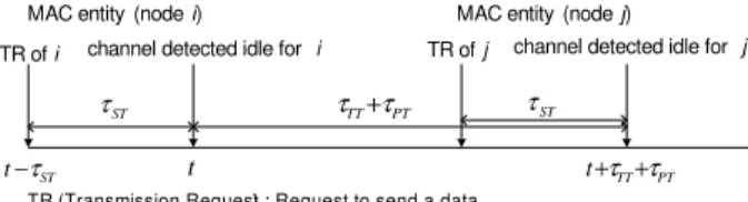
B. Concept of “Ambiguity Time Window”
We introduced this concept [1] in order to quantitatively characterize the ambiguity in the CSMA context of the ex-pression “Channel detected idle at an instant t in a MAC
ST
t−τ
ST
τ MAC entity (node i)
t
channel detected idle for i
PT TT τ
τ +
ST
τ
channel detected idle for j
PT TT
t+τ +τ
TR of i TR of j
TR (Transmission Request) : Request to send a data
MAC entity (node j)
Fig. 1. Ambiguity Time Window.
entity”. This expression is ambiguous because it only expresses a local view whereas the channel is geographically distributed. For example, a MAC entity i sees the channel idle at the instant t but just before t, another one has just sent a frame and this frame has not arrived at i yet, a collision can occur when i sends its frame. So a local view can be different from a global one which can create collision situations. The concept of “Ambiguity Time Window” represents the maximal duration which is possible between the decision to send a frame by a MAC entity and the inevitability of the occurrence of a collision on this frame. The quantitative characterization depends on the transceiver parameters (τST, τT T) and the
maximum propagation time between two nodes (call τPT this
Propagation Time).
The “Ambiguity Time Window” is represented on Fig. 1. The MAC entity i receives a Transmission Request (TR) from the upper layer at the instant (t − τST) to send a data and then
makes a CCA during τST. We suppose that the channel is
detected idle at the instant t(= t −τST+τST) and then the MAC
entity i decides to send its frame. Its transceiver turns to the Transmit state (during τT T), and then the frame is transmitted
and arrives at the level of the most remote MAC entity j at the instant (t + τT T+ τPT).
Suppose that the MAC entity j is just, at this instant, finishing
to make a CCA (started by a TR at the instant (t + τT T+
τPT− τST)) and as the channel has been detected idle during τST, it decides to send a frame at the instant (t + τT T+ τPT).
So we have, at this instant, a situation of an inevitable future physical collision. Actually, the beginning of the arrival of the
frame coming from the MAC entity i coincides with the instant where the transceiver of the MAC entity j turns around to go in the transmitter state (duration τT T). During this time τT T,
the MAC entity j is blind. Then at the end of τT T, the MAC
entity j will start to send its frame and we will then have the physical collision.
The duration (τT T+ τPT) is the length of the “Ambiguity
Time Window”.
C. On the priorities associated to the frames
The priorities of the frames are extracted from the values of an identifier (ID) field. We can consider two types of priorities [9] (static priorities, hybrid priorities) but here we only consider static priorities i.e. each flow has a unique priority (specified out of line) and all the frames of this flow have this priority.
D. Concept of tournament
The tournament consists in the comparison of the priorities of the contending frames. This allows to transform a situation which would have been a “collision situation” (if we have the
strict CSMA mechanism i.e. only based on the scheme “Listen before Send”) into a “winner-loser(s) situation”. There will be only one winner who has the highest priority among the contending frames. The winner can send its frame after the tournament while the losers have to wait until the end of the frame transmission of the winner and restart the tournament.
The good functioning of a tournament is dependent of the duration of the ID field. It is the consideration of the constraint
done by the Ambiguity Time Window which allows to specify correctly these durations.
III. CANLIKE PROTOCOL
A. Principle
As introduced, CANlike is an adaptation of the MAC protocol of the wired bus CAN to the wireless network.
In the wired bus CAN, MAC entities can send bits and listen to the channel simultaneously. Each MAC entity has a unique ID (identifier) field placed at the beginning of the frame. The ID represents the priority and allows to do the channel access tournament. The tournament is done by a comparison bit by bit of the same rank among the IDs of the frames trying to access the channel. In one bit-by-bit comparison, a bit 0 which is a dominant bit overwrites a bit 1 which is a recessive bit. The MAC entity which has the highest priority will be the only one winner after the tournament and it will send its frame.
In the wireless context, the bus CAN protocol cannot be directly implemented with wireless transceivers since the transceivers cannot transmit and receive simultaneously in the same channel, so we consider the proposal, which has been done in [8]: one slot time (duration) is provided for each ID bit, a dominant bit consists in the sending of a carrier pulse during its duration while a recessive bit consists in the sensing/listening of the channel during its duration.
So, in each MAC entity, the tournament on each bit has the following characteristics:
• The MAC entity has a dominant bit: it sends a carrier
pulse on the channel and at the end of the sending, it wins by definition the tournament related to this bit and then continues the tournament on the next bit.
• The MAC entity has a recessive bit: either it senses
a carrier pulse, then it loses the tournament related to this bit and stops the tournament phase, or it senses nothing (that means that there is no dominant bit sent by another MAC entity) and then it can continue the tournament on the next bit.
B. Main points to consider
Necessity of a synchronization phase: The start of the
tournament by a MAC entity (the sending of the first ID bit i.e. the MSB bit) must be preceded by the sending of a synchronization (SYN) signal which is an energy pulse (carrier pulse like a dominant bit). The role of the SYN signal is to announce to the other MAC entities the arrival of the ID of this MAC entity and then to provide for them a time reference for the analysis of this ID.
(TT PT) TT
t+τ +τ +τ
MAC Entity i MAC Entity j
ls t : SYN signal ls TT t τ+ t t t propagation 1 t 3 t tg sending t1= t + τT T+ ls; t3= t + (τT T+ τPT) + ls+ τPT Fig. 2. CANlike: SYN signals.
A MAC entity, which has detected a SYN signal without itself having sent before a SYN signal, do not participate to the tournament.
Necessity of a guard time: Having in mind the time
interval defined by the Ambiguity Time Window, several MAC entities can send the SYN signals which will be overlapping. Consequently, in each MAC entity among these MAC entities, the end of the SYN signal sending can be overtaken by the end of the SYN signal arrivals. Considering such situation, a MAC entity cannot send the first ID bit immediately after the SYN signal sending. We need to have a guard time following the SYN signal and then we send the first ID bit. The guard time guarantees that after this time, we have a clean (idle) channel
i.e. there is no more residue of the SYN activity.
We also have the overlap between the ID bits of different rank, then we need to add a guard time at the end of each ID bit.
Necessity of a channel observation time: We need an
ob-servation time (noted TOBS1) before the start of a tournament. The role of this time is to ensure that the channel is globally idle and there is neither a tournament nor a transmission in progress.
C. The stages of CANlike
We can now precise the global tournament. All the contend-ing nodes listen to the channel durcontend-ing TOBS1. If the channel is detected idle, all the contending nodes send a SYN signal and then do the tournament by comparing their ID bits from the MSB bit to the LSB bit. The only winner is the one who did not lose on any bit during the tournament. The winner will send its frame while the losers will wait until the end of the frame transmission of the winner before to try to do a new tournament.
D. Specification of CANlike parameters
We have to specify the following parameters: the duration of the SYN signal (noted ls), the duration of the guard time
(noted tg), the length of the ID bit (noted lb) and TOBS1.
lsduration: The SYN signal must be detected by a receiver
MAC entity. Then:
ls≥ τST (1)
tg value: Suppose that a MAC entity i sends the SYN
signal. The duration tg is the biggest difference between the
end of the SYN signal sending and the end of the propagation of a SYN signal of another MAC entity j.
In order to specify the value tg, we consider the Ambiguity
MAC Entity j 2PT TT t+τ +τ t propagation lb lb MAC Entity i MAC Entity j lb lb MAC Entity i t t t : dominant bit : recessive bit t−τTT b l t + ( ) t +lb PT TT t+τ +τ ) (TT PT t−τ +τ b TT l t−τ + b TT PT l t+2τ +τ +
(a). Case 1 (b). Case 2 propagation
: dominant bit : recessive bit
Fig. 3. CANlike: Evaluation of lb.
Time Window concept with the most constrained scenario which is represented on Fig. 2: the MAC entity i decides to send its SYN signal at the instant t while the MAC entity j decides to send its SYN signal at the instant t + (τT T+ τPT)
i.e. the latest with respect to the one sent by i.
We can see (Fig. 2) that we do not have an overtaking in the MAC entity j because it sends later and that we have an overtaking in the MAC entity i (because it sent earlier). This overtaking (= t3− t1) defines the value of tg. Then we have:
tg= 2τPT+ τT T (2)
Remark: As tg> τT T, we consider that, during the guard
time, a MAC entity makes the turnaround if necessary, which depends on the first ID bit.If the 1st ID bit is a dominant one, it is not necessary (as the MAC entity was in the transmit state for the sending of the SYN signal); if it is a recessive one, we do the turnaround.
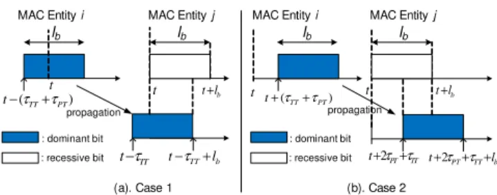
lb duration: We analyze the tournament (after the SYN
phase) between the first ID bit of the MAC entity i (this bit is a dominant bit) and the first ID bit of the MAC entity j (this bit is a recessive bit) by considering, always in the context of the Ambiguity Time Window, the following scenarios:
• The MAC entity j starts listening to the channel at the time t and ends the listening state at the time t + lb.
• The MAC entity i starts the sending of the carrier pulse either (case 1) at the time t − (τT T+ τPT) i.e. at the
earliest (Fig. 3.a), or (case 2) at the time t + (τT T+
τPT) i.e. at the latest (Fig. 3.b).
For the case 1 (Fig. 3.a), the carrier pulse sent by i arrives at
j at t − (τT T+ τPT) + τPT = t − τT T and lasts till t − τT T+ lb.
This arrival must be detected by j (i.e. j sees this arrival during at least one τST), the condition is: t − τT T+ lb≥ t + τST (i.e.
an overlap at the beginning of the listening state) which gives:
lb≥ τT T+ τST (3)
For the case 2 (Fig. 3.b), the carrier pulse sent by i arrives at j at t + (τT T+ τPT) + τPT = t + τT T+ 2τPT and lasts till
t+ τT T+ 2τPT+ lb. The MAC entiy j must detect this carrier
pulse arrival (i.e. j sees this arrival during at least one τST),
the condition is: t + τT T+ 2τPT+ τST≤ t + lb (i.e. an overlap
at the end of the listening state) which gives:
B A
Ambiguity
Time Window : dominant bit : recessive bit SYN SYN 0 0 0 1 1 1 TOBS1 TOBS1 data tg tg tg tg tg tg tg
Fig. 4. Example of a time diagram of CANlike.
Considering the constraints (3) and (4), we need
lb≥ 2τPT+ τT T+ τST. We take here:
lb= 2τPT+ τT T+ τST (5)
Note that, in the case 2, the end of the arrival of the carrier pulse is higher than t +lb. The difference is 2τPT+ τT T
which is equal to tg (2). We thus need a tg added at the end
of each ID bit in order to have a clean system (when the tournament between the bits of a given rank starts, there is no thing on the channel from the tournament between the bits of the previous rank).
We also consider that during tg, a MAC entity does the
turnaround if necessary, which depends on the next ID bit. If next ID bit and the current one are identical, it is not necessary; if they are different, we have to do the turnaround.
TOBS1 duration: TOBS1 must be higher than the
maxi-mum duration during a tournament where the channel is idle. This extreme case is when we have a channel access of only one MAC entity which has all recessive ID bits. Considering the ID field of n bits, the channel will be idle during n(lb+tg),
thus TOBS1 > n(lb+ tg). We take: TOBS1 = (n + 1)(lb+ tg).
TOBS1 = (n + 1)(4τPT+ 2τT T+ τST) (6)
E. Summary
We present in Tab. I the values of the parameters which characterize the CANlike protocol.
Concerning the duration of the SYN signal ls, we only
indi-cated its constraint in (1) (ls> τST). We consider that it is not
necessary to distinguish its duration from the ID bit duration and then we take the same value (ls= lb).
lb= ls 2τPT+ τT T+ τST
tg(for lband ls) 2τPT+ τT T
TOBS1 (n + 1)(4τPT+ 2τT T+ τST)
TABLE I. CANLIKE PARAMETERS.
From these parameters, we can deduce the time for access-ing the channel (called τa) by the winner. τa composes of the
observation phase, the SYN phase and the tournament phase: τa = TOBS1 + (ls+ tg) + n(lb+ tg)
τa = 2(n + 1)(4τPT+ 2τT T+ τST) (7)
F. Example of a time diagram of CANlike
We present an example of the tournament of CANlike on Fig. 4. We consider an ID field of 3 bits and the tournament of 2 nodes A and B which have the priorities (1; 0; 0) and (1; 0; 1) respectively. Thus A has a higher priority than B. The
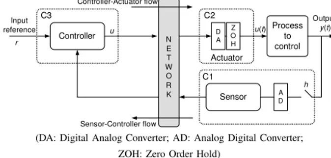
N E T W O R K Process to control h y(t) u(t) Controller-Actuator flow Actuator Sensor-Controller flow Controller u DA Z O H A D Sensor Input reference r C1 C2 C3 Output
(DA: Digital Analog Converter; AD: Analog Digital Converter; ZOH: Zero Order Hold)
Fig. 5. Implementation of a process control application through a network. node B starts the tournament later (of one Ambiguity Time Window) than the node A. At the 1st ID bit, the two nodes, which have recessive bits, find the channel idle; at the 2nd ID bit, the two nodes have dominant bits so they continue the next bit; at the last ID bit, A has a dominant bit so it is the winner by definition while B, which has a recessive bit, finds the channel busy and then B stops the tournament. A then sends its data.
IV. CONCLUSION
In this paper, we have tried to do an exhaustive and pedagogical presentation of the specification process of the CANlike protocol. We have shown how the main elements of the tournament (synchronization signal, bits of the ID field, guard time, TOBS1) depend on the physical parameters (τST, τT T, τPT) and on the concept of “Ambiguity time
win-dow”.
We want also to show in this conclusion the interest of this protocol, in considering real-time traffic and in com-parison with a protocol used very often in the wireless context (IEEE.802.11-DCF). In this goal, we have, at first, considered an example of a process control application the characteristics of which are: the process to control has the
transfer function [10] G(s) = 1000
s(s+1) and the controller is
a Proportional Derivative (PD) controller (transfer function:
K(1 + Tds)) in order to have a phase margin of 45◦ which
imposes K = 0.7291; Td= 0.0297 s. The input reference r(t)
is a unity position step and the feedback is made by taking directly the output y(t). The performance of this application
i.e. the Quality of Control (QoC) is evaluated by means of a
cost function ITSE (Integral of Time weighted Square Error) noted J with J =R
t(r(t)−y(t))2dt. We call J0the value which is obtained without the network. Then we have considered the implementation of such four Process control applications
(Pi with i = {1,2,3,4}) through a network where the MAC
protocol is either IEEE 802.11-DCF protocol or the CANlike protocol. The analysis of the implementation has been done by using the tool TrueTime [11] and by considering, for the frame format the frame of IEEE 802.11-DCF (for the CANlike protocol we add also an ID field of 8 bits).
The scheme of the implementation of a process control application through a network is shown on Fig. 5. We have two frame flows: the sensor-controller flow (noted fsc) and
the controller-actuator flow (noted fca). Then considering the
implementation of the four applications through the network, we have eight flows which share the netrwork and compete for
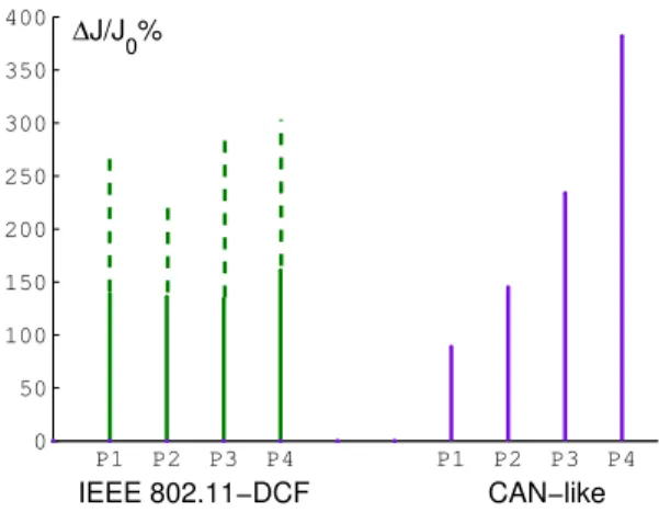
P1 P2 P3 P4 P1 P2 P3 P4 0 50 100 150 200 250 300 350 400 ∆J/J 0% CAN−like IEEE 802.11−DCF
Fig. 6. Graphic representation of the QoC (∆J/J0%).
its use: fsci, fcai, with i = {1,2,3,4}. Accounting for the delays
which will affect the frames of these flows, the performances obtained for the four applications implemented through a network will be obviously less good than for the application implemented without the network and will also depend on the protocol (IEEE 802.11-DCF, CANlike). Concerning CANlike, we consider the following scheme of the priorities for the frames of the flows fsc and fca: prio fca1> prio fca2> prio
fca3> prio fca4> prio fsc1> prio fsc2> prio fsc3> prio fsc4 which means that we consider: importance P1> importance
P2> importance P3> importance P4.
The comparison between the performances obtained, by the implementation of the four process control applications, with the two protocols, IEEE 802.11-DCF and CANlike, is made with the performance criteria J−J0
J0 % =
∆J
J0% which shows the
deviation of the QoC in comparison with the result obtained (J0) when the implementation is done without network (this comparison shows the influence of the delays induced by the protocols) The higher the value ∆J
J0% is, the more degraded the
QoC is.
The Fig 6 shows the results which have been obtained. Concerning the IEEE 802.11-DCF we did 20 simulations and we have represented the mean value by a simple line and the maximum gap between the results of the 20 simulations with a dotted underline. We see that this protocol induces big gaps between the performances, which can be obtained for each application, and then it cannot guarantee a performance (i.e. we have random performances).
On the other hand, we see that the CANlike protocol guar-antees performances which obviously depend on the priority associated to the flows of the process control applications (higher is the priority, better is the performance). We have here deterministic performances.
ACKNOWLEDGMENT
This work has been partly funded by the project OSEO AMIC-TCP (Architecture Multiplexage Informatique Commu-nication pour Transport en Commun de Personnes). We want to express here our sincere thanks.
REFERENCES
[1] H. Nguyen Xuan, G. Juanole, G. Mouney, and C. Calmettes, “Wireless communication networks and process control applications: studying the influence of MAC protocols,” in Proc. IEEE Globecom 2010, Workshop
SaCoNAS, Miami, Forida, USA, Dec 2010.
[2] B. Crow, W. I., K. L.G., and S. P.T., “IEEE 802.11 Wireless Local Area Networks,” IEEE Communications Magazine, vol. 35, pp. 116– 126, September 1997.
[3] 802.11e 2005, “IEEE Standard for Information Technology - Telecom-munications and Information Exchange Between Systems - Local and Metropolitan Area Networks - Specific Requirements Part 11: Wireless LAN Medium Access Control (MAC) and Physical Layer (PHY) Specifications Amendment 8: Medium Access Control (MAC) Quality of Service Enhancements,” 2005.
[4] D.-J. Deng and R.-S. Chang, “A Priority Scheme for IEEE 802.11 DCF Access Method,” IEICE Trans Commun (Inst Electron Inf Commun
Eng), vol. E82-B, no. 1, pp. 96–102, 1999.
[5] J. Sobrinho and A. Krishnakumar, “Real-time traffic over the IEEE 802.11 Medium Access Control Layer,” Bell Labs Technical Journal, vol. 10, no. 1, pp. 172–187, 1996.
[6] A. Pal, A. Dogan, and F. Özgüner, “MAC Layer Protocols for Real-Time Traffic in Ad-Hoc Wireless Networks,” in Proceedings of the 2002
International Conference on Parallel Processing (ICPP’02).
Washing-ton, DC, USA: IEEE Computer Society, 2002, pp. 539–546. [7] G. Bosch, “Can specification 2.0, 1991. [online]. Available:
www.can-cia.de/fileadmin/cia/specifications/can20a.pdf.”
[8] N. Pereira, B. Andersson, and E. Tovar, “WiDom: A Dominance Protocol for Wireless Medium Access,” IEEE Transactions on Industrial
Informatics, vol. 3, no. 2, pp. 120–130, May 2007.
[9] H. Nguyen Xuan, “Réseaux de communication et applications de contrôle-commande,” Ph.D. dissertation, Univ de Toulouse, INSA, LAAS, Toulouse, France, Dec 2011.
[10] K. J. Åström and B. Wittenmark, Computer-controlled systems: Theory
and design, 3rd ed. Prentice Hall, 1997.
[11] M. Ohlin, D. Henriksson, and A. Cervin, TrueTime 1.5 – Reference