HAL Id: hal-02071160
https://hal.archives-ouvertes.fr/hal-02071160
Submitted on 18 Mar 2019
HAL is a multi-disciplinary open access
archive for the deposit and dissemination of
sci-entific research documents, whether they are
pub-lished or not. The documents may come from
teaching and research institutions in France or
abroad, or from public or private research centers.
L’archive ouverte pluridisciplinaire HAL, est
destinée au dépôt et à la diffusion de documents
scientifiques de niveau recherche, publiés ou non,
émanant des établissements d’enseignement et de
recherche français ou étrangers, des laboratoires
publics ou privés.
Development of a compact bushing for NBI
H. de Esch, A. Simonin, C. Grand, Bruno Lepetit, Didier Lemoine, M.
Márquez-Mijares, T. Minea, L. Caillault, B. Seznec, T. Jager, et al.
To cite this version:
H. de Esch, A. Simonin, C. Grand, Bruno Lepetit, Didier Lemoine, et al.. Development of a compact
bushing for NBI. FIFTH INTERNATIONAL SYMPOSIUM ON NEGATIVE IONS, BEAMS AND
SOURCES (NIBS 2016), Sep 2016, Oxford, United Kingdom. pp.060003, �10.1063/1.4995790�.
�hal-02071160�
Development of a Compact Bushing for NBI
H.P.L. de Esch
1, a), A. Simonin
1, C. Grand
1,
B. Lepetit
2, D. Lemoine
2, M. Márquez-Mijares
2, †,
T. Minea
3, L. Caillault
3, B. Seznec
3, T. Jager
3,
E. Odic
4, M.J. Kirkpatrick
4, Ph. Teste
4, Ph. Dessante
4, K. Almaksour
41CEA-Cadarache, IRFM, F-13108 St. Paul-lez-Durance, France.
2Université de Toulouse, UPS, Laboratoire Collisions Agrégats Réactivité, IRSAMC, F-31062 Toulouse, France 3Laboratoire de Physique des Gaz et Plasmas, UMR 8578, CNRS, Univ. Paris-Sud, Université Paris-Saclay, Orsay
CEDEX, 91405, France
4GeePs Group of electrical engineering - Paris, UMR CNRS 8507, CentraleSupélec, Univ. Paris-Sud, Université
Paris-Saclay, Sorbonne Universités, UPMC Univ Paris 06,
3 & 11 rue Joliot-Curie, Plateau de Moulon 91192 Gif-sur-Yvette CEDEX, France
† Instituto Superior de Tecnologías y Ciencias Aplicadas, Avenida Salvador Allende 1110, Quinta de los Molinos,
La Habana, Cuba
a)Corresponding author: [email protected]
Abstract. Research into a novel type of compact bushing is being conducted through the HVIV (High Voltage holding In
Vacuum) partnership between CEA-Cadarache1, GeePs-Centralesupélec4, LPGP3 and LCAR2. The bushing aims to concentrate the high electric field inside its interior, rather than in the vacuum tank. Hence the field emission current is also concentrated inside the bushing and it can be attempted to suppress this so-called dark current by conditioning the internal surfaces and by adding gas.
LCAR have performed theoretical quantum mechanical studies of electron field emission and the role of adsorbates in changing the work function. LPGP studied the ionization of gas due to field emission current and the behavior of micro particles exposed to emissive electron current in the vacuum gap under high electric fields. Experiments at Geeps have clarified the role of surface conditioning in reducing the dark current. Geeps also found that adding low pressure nitrogen gas to the vacuum is much more effective than helium in reducing the field emission. An interesting observation is the growth of carbon structures after exposure of an electrode to the electric field. Finally, IRFM have performed experiments on a single stage test bushing that features a 36 cm high porcelain insulator and two cylindrical electrode surfaces in vacuum or low-pressure gas. Using 0.1 Pa N2 gas, the voltage holding exceeded 185 kV over a 40 mm “vacuum” gap without dark current. Above this voltage, exterior breakdowns occurred over the insulator, which was in air.
The project will finish with the fabrication of a 2-stage compact bushing, capable to withstand 400 kV.
INTRODUCTION
SIPHORE [1] is a potential photo neutralizer based system for Neutral Beam Injection (NBI) on the future nuclear fusion demonstration reactor DEMO. SIPHORE accelerates 100 keV pre-accelerated negative ion beams in a single step to around 1 MeV. These 1 MeV beams are then efficiently photo neutralized and drift into the DEMO tokamak where they heat the magnetically confined plasma.
The high voltage bushing is a component that transmits high voltage from a transmission line, typically filled with high pressure SF6, into a component like an ion source and an accelerator suspended in vacuum. The bushing
should not only transmit high voltage, but also provide the services for the beam source such as gas, cooling water and electrical power. The present research is only concerned with the high-voltage aspects of the bushing, although the design of the new bushing is compatible with the provision of these services.
Experiments have shown that an electron current flows between two surfaces in vacuum at a different electric potential. This occurs at macroscopic electric fields that are much lower than expected by theory for electron field emission. This so-called dark current increases exponentially with the voltage. The dark current poses a significant limitation in high-voltage holding: it causes damage due to power deposition on surfaces and it can provoke electrical breakdowns. However, experiments at IRFM, CEA-Cadarache, have shown that adding hydrogen or helium gas to the vacuum tank reduces or suppresses this dark current [2].
For these reasons, coordinated research on the field emission in large installations is necessary. The project HVIV unites on the one hand a modelling effort (by LCAR and LPGP) and on the other hand experimentation: detailed small-scale experiments by GeePs-Centralesupélec and large scale experiments by IRFM.
The work will converge in the construction of a 2-stage 400 kV test bushing at IRFM. Its design is finished and the bushing is currently being manufactured. The bushing concentrates the strongest electric field in its interior. It is closed, thus allowing the presence of low-pressure gas to suppress the dark current. This allows the exterior field to be lower which should lead to a lower dark current in the vacuum vessel housing the beam source.
MODELING
Modeling was performed by LCAR and LPGP. LCAR have performed theoretical quantum mechanical studies of electron field emission and the role of adsorbates in changing the work function. LPGP studied the ionization of gas due to field emission current and the behavior of micro particles exposed to emissive electron current in the vacuum gap under high electric fields.
Electron field emission is caused by quantum tunneling. Cold field emission is described by the Fowler-Nordheim equation [3, 4]:
E
y
E
y
v
y
t
E
j
5 5 . 1 9 2 2 63
.
7947
10
;
)
(
10
83
.
6
exp
)
(
10
54
.
1
(1)9
/
)
ln(
9
/
1
)
(
;
3
/
)
ln(
1
)
(
y
y
2y
2y
t
y
y
2y
2y
v
(2)Where j is the electron current density in A/m2, E is the local electric field strength in V/m and is the local work function in eV. The current density depends exponentially on the electric field and the work function. The roughness of the surface locally enhances the electric field and can therefore strongly increase the dark current. Layers of adsorbates change the work function and thus the dark current. During the project, it was experimentally found that carbon structures can “grow” when a metallic electrode is exposed to the electric field [5]. Finally, also micro inclusions in the electrode material can be a source of dark current [6].
Quantum Mechanical Modeling (LCAR)
The small-scale experiments performed at Geeps-CentraleSupélec (see below) suggest that an important parameter controlling emission may be the cathode carbon coverage: indeed, raising the gas pressure during field emission is likely to reduce simultaneously the amount of carbon on the surface and the emitted flux. Presence of carbon may be the result of unwanted contamination and may be a common phenomenon in many engineering applications. This contamination may be the product of physisorbed hydrocarbon dehydrogenation induced by some ionic bombardment stemming from the ambient gas, after ionization by the electron flux emitted from the cathode [5]. Low gas pressure may lead to a low ionic bombardment possibly to a carbon layer growth whereas a higher ion flux at higher pressure may destroy this layer [7]. The question now turns into: how can the presence of such carbon deposits influence the electronic emission level? Equation (1) indicates that the two parameters of the emitting surface which influence electronic emission are the work function and the local electric field E. Hence, in the following, we first consider the effect of the presence of carbon adsorbed layers on the work function [5,8]. Then, we study the effect of the morphology of the surface on the electric field as it can be enhanced locally by the presence of nanoscale tips on the emitting surface [9]. These two studies are performed within the frame of the Density Functional Theory (DFT). The ab initio total-energy and molecular dynamics program VASP (Vienna ab
initio simulation program) developed at the Institut für Materialphysik of the Universität Wien has been used for all
these DFT calculations [10].
The effect of carbon adsorption on the work function is studied for surfaces made of tungsten (100) and tungsten carbide (0001) which are the most common materials used to manufacture electrodes. We first compute the work functions for clean surfaces. Next, we allow carbon to adsorb on the different hollow, bridge, top sites of the surface and we consider up to 2 monolayers, which involves a huge amount of computation in order to probe many different configurations. The main outcome is that the presence of the carbon contamination increases the work function with respect to its clean surface value. This results from the larger electronegativity of carbon with respect to tungsten. It is known that the WC molecule has a large dipole moment resulting from a partial shift of the electronic density from tungsten to carbon. Assuming that each adsorbate induces a dipole moment 0 with the substrate, the work
function change induced by the presence of the adsorbate is: eN0 0 , where N is the number of adsorbates per unit area, e the electron charge, 0 the vacuum permittivity. N0 is thus the electric dipole per unit area induced
by the presence of the adsorbate. This theoretical work function increase with carbon contamination is in apparent contradiction with the experimental observation that the electronic emission increases with contamination. But the theoretical results were obtained for flat adsorption layers, excluding the possibility that the adsorbed atoms are arranged to form spike-like emitting sites. We therefore conclude that the increase of emission observed in the experiments when a C contamination layer grows is not related to the chemical nature of the contaminant but rather to the morphology of this contamination layer.
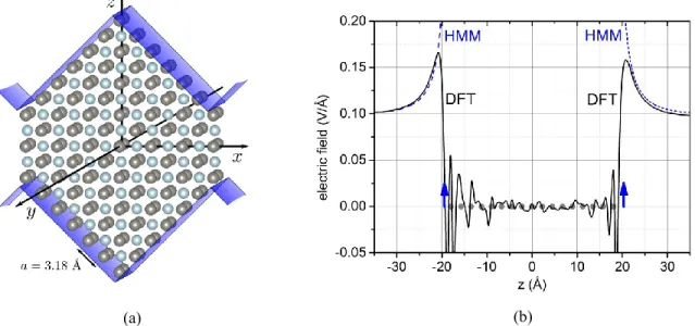
Hence, we now discuss possible field enhancement on rough surfaces by considering the protrusion model of fig. 1(a). It shows two symmetrical tungsten surfaces at top and bottom with defects which consist of right angle steps parallel to the (100) and (010) crystallographic planes. Such steps are common surface defects at the atomic scale. Periodic extension along the x direction generates two sawtooth structures, the upper one associated to the cathode, the lower one to the anode when embedded in an external electrostatic field E∞=1 GV/m (=0.1 V/Å) at large
distance. The electrostatic field near this structure can be extracted from DFT calculations. Only a modest enhancement, barely more than 50%, is observed on the induced field close to the surface along the z axis (fig. 1(b)). Similar enhancement can be achieved within a Homogeneous Metal Model (HMM), which is a classical conductor electrostatic model where the atoms are replaced by metallic planes at the appropriate locations (the arrows on fig. 1(b) and where the tip line defined by the sharp intersection of pairs of metallic planes is smoothed by acquiring a radius of curvature of the order of the atomic radius ra [9]. It can be shown that the appropriate step size L to achieve
a given field enhancement β is given by: 4 2 9
a r
L [9]. Limited field enhancement is to be expected from atomic- and nano-size scale defects and micrometer-size or larger steps are thus necessary to achieve enhancement by one order of magnitude: β10 or more.
(a) (b)
FIGURE 1. (a): Atomic level model of a tungsten right angle step built from the (100) and (010) crystallographic planes used for
the DFT calculation. The step extends infinitely along the y direction and repeats periodically along x to form two symmetrical sawtooth structures, the upper one for a cathode configuration and the lower one for the anode. These geometries correspond to
common emitting structures at the atomic scale. The inverted roof shapes correspond to the macroscopic HMM (Homogeneous Metal Model), which is a classical conductor model of the metallic structure. (b): Induced electric field along the z axis for the HMM (dashed line) and DFT (full line) models of the emitting structure embedded in an external field E∞=1 GV/m. In the DFT
calculations, the induced electrostatic field is the difference between the total fields for E∞=1 GV/m and 0 V/m. The dots indicate
the locations of the atomic planes and the vertical arrows those of the charge barycenters which are the effective metallic plane locations in the HMM.
Modeling of Micro Tips and Micro Particles (LPGP)
The modeling performed at LPGP addressed two phenomena: (i) the ionization of the gas at reduced pressure and (ii) the eventual role played by the clumps, as originally proposed by Cranberg [11], and developed by Latham [6].
(i) In vacuum, the high voltage applied between two electrodes can lead to electron emission, essentially from surface protrusions (here-after called ‘tip’) where the local electric field is enhanced with respect to macroscopic field by a factor , essentially due to the sharp shape of this tip. First, only the cold emission operates (Eq. 1). But, the higher the current passing through the tip (from the cathode to the tip apex), the higher the Joule effect (heating) is. Increasing the apex temperature leads to higher thermo-ionic emission and finally the current released from the tip is much higher. In this case, the electron emitted current at the tip (j) is described by Murphy and Good’s theory [12]. This model is in good agreement (<23% found in [13]) with an emission model developed by Teste et al. [14]). The <23% agreement is considered good because the measurement uncertainty on the work function caused by the crystal orientation at the surface (For Tungsten, a variation of 0.9 eV has been observed [15]), can lead to an uncertainty of more than 50% on the electron emission current. Hence, the current depends on the temperature and electric field at the tip apex. As the temperature along the tip is strongly related to the current flowing through, the solution of this problem can be found numerically by solving the heat equation. For the sake of clarity, the 1D heat equation (3) is written here for a cylindrical tip (of height H and radius R), but it can be easily extended to any other shapes of axisymmetric tips [13].
4 4
2 2 2 2 2,
2
R
j
E
T
R
T
T
dz
T
d
R
s s c
(3)with the following boundary conditions:
E
T
T
T
T
T
T
K
dz
dT
CATHODE z s s N H z300
,
4
4 0
(4)where N represents the heat flux at the tip apex due to the Nottingham effect [16], that can cool down or heat up the
tip:
W
E
T
e
T
E
j
N N,
,
(5)s is the Stefan constant. , c, and s represent the thermal and electrical conductivities, and the surface
emissivity respectively, for the electrode material. WN denotes the Nottingham energy [16-18] and can be written as
analytical functions of the local temperature T(z) and the microscopic electric field E. Finally, T represents the
ambient temperature in the thermal radiation law.
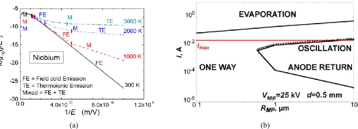
The emitted electron current, shown in Fig. 2(a), obeys to the Fowler-Nordheim law, Eq. (1) for cold emission (FE), only if the tip stays cold (300K), otherwise the Thermionic Emission (TE) starts to play a significant role and a mixed emission regimen governs the tip emission. For a single niobium elliptic tip of 10 µm height and 1 µm radius, the emitted electron current just before melting the tip is ~22 mA corresponding to a current density je = 2.6 x 10¹²
Am-2, because only a small area of the apex is effective to emit electrons. This electron current can be at the origin
of the dark current of several mA, as experimentally recorded [2]. It could be taken as an indication that only one micro-tip dominates the emission. If it is destroyed, another one can take the control.
Let us focus on the electron ionization of the residual gas and the effect of the positive ions on the tip heating. Indeed, it was experimentally found that passing from vacuum (limit residual pressure < 10-3 Pa) to a reduced
(a) (b)
FIGURE 2. (a) Family of Fowler-Nordheim-like characteristics of the electron emitted current from a micro-tip for several tip
temperatures indicating the coexistence of Field Emission (FE) and Thermionic Emission (TE). (b) Different regimes of MP dynamics versus the MP radius (RMP). The figure corresponds to a constant voltage V =25 kV and gap distance d=0.5 mm.
Hence, considering the electron current emitted by a micro-tip, evaluated using the theory of Murphy and Good with the tip temperature as solution of Eq. (3), it is possible to evaluate the ionization of the gas (atoms or molecules) at low pressure. The Monte Carlo algorithm [19] was adapted for Helium, in our case, and the ionization probability is summarized in Table 1 for Helium pressures between 10-3 to 0.1 Pa and inter-electrode gap distances
from 200 µm to 1 m. Even for the largest gap and the highest pressure the ionization probability stays below 10-3, meaning that less than one electron is able to ionize the gas among 1000 electrons leaving the tip under 30 MV/m accelerating field. Considering the ion contribution to the cathode heating by Joule effect in Eq. (3), the emitted electron current from the tip changes by less than 5%. Therefore we can conclude that the residual ionization can neither ionize significantly the gas nor modify significantly the emitted electron current from the cathode (‘dark current’).
TABLE 1. Ionization probability due to the electrons emitted from an elliptical micro-tip (H = 1 µm, R = 0.15 µm) accelerated in
a field of 30 MV/m for different helium gas pressures and different gaps.
Gap distance He Pressure =0.1 Pa He Pressure =0.01 Pa He Pressure = 10-3 Pa
1 m 0.18 x 10⁻³ 0.18 x 10⁻⁴ 0.18 x 10⁻⁵
0.1 m 0.18 x 10⁻⁴ 0.18 x 10⁻⁵ 0.15 x 10⁻⁶
0.2 x 10⁻³ m 0.14 x 10⁻⁵ 0.13 x 10⁻⁶ < 10-8
(ii) The last effect probed by the modeling at LPGP jointly with GeePS was Cranberg’s scenario, i.e., the effect of a micro-particle (denoted hereafter MP) detaching from the anode (with a charge corresponding to the anode potential) and moving towards the cathode along the micro-tip axis and being irradiated by the energetic electrons emitted from the tip. Hence, the charge of the MP can change by collecting and/or emitting electrons, and its mass can reduced by evaporation (heating). The details of the modelling procedure can be found in [20]. It is found a more complex behavior of the MP than the one proposed by Cranberg [11].
Indeed, as shown in Fig. 2(b), four regimes are possible, depending on the size of the MP and the electron current. The horizontal (red) line indicates the maximum electron current level that could be emitted by a single tip. So, the MP evaporation can occur only if several micro-tips act simultaneously, or if the dark current is very high. For low emission current from the tip (in the µA range) the MP travels directly from the anode to the cathode (‘ONE WAY’- Fig. 2(b)). If the particles are larger than 1 µm (radius), and the current ranges from 10 µA to 10 mA, than MPs can return to the anode (no effect on the cathode), or even oscillate, as described by Cranberg.
Micro particles reaching the cathode often have a conditioning effect: the tip aspect ratio is reduced by the impact, and consequently the electron emission is reduced and the high voltage holding of the system is increased.
EXPERIMENTS
Small-scale experiments have been conducted by Geeps-Centralesupélec. These experiments were performed on two small electrodes, one flat, the other either spherical or a needle. The size of the electrodes and the vacuum gap was of the order of centimeters. The maximum voltage that could be applied was 30 kV.
Full-scale experiments have been done at IRFM on a single-stage test bushing. The cylindrical electrodes were separated by a 36 cm high cylindrical porcelain insulator (SiO2 containing some Zr, 400 mm) and a 40 or 25 mm
vacuum gap. Up to 200 kV could be applied to this system. The cylindrical cathode has a surface area of 0.34 m2.
Small Scale Experiments (Geeps-CentraleSupélec)
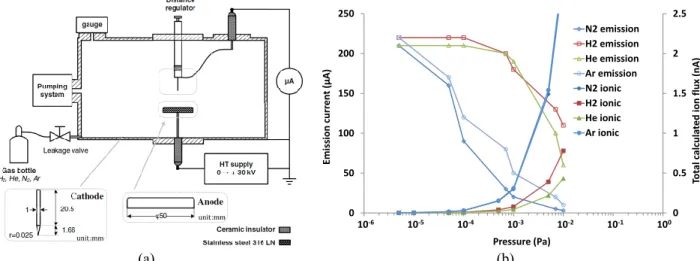
The experimental set-up is in Fig. 3(a). A commercially available tungsten carbide (WC) point cathode of precisely controlled shape (tip radius is 25 µm) is separated from a flat anode by 20 mm. Investigations concerned the quantification of the effect on field emission of increasing residual gas pressure by the injection of different gases. It was shown experimentally that argon and nitrogen have stronger inhibitory effects on field emission than do hydrogen and helium. As seen in Fig. 3(b), at the same applied electric potential and using the same tungsten carbide point cathode, as a function of gas pressure, field emission current is observed to decrease by over 90% for nitrogen and argon gas injection, with lower magnitude decreases with hydrogen and helium. The data are average field emission current over a period of several minutes for each point depicted in the figure. Also shown in the figure is the estimated ionic flux for the different gases: higher calculated flux for argon and nitrogen are due to their greater collision cross-section. The cross-section data was calculated based on the local electric field around a parabolic point having the same curvature radius as the electrode used in experiments. This means that a significant portion of the ions that are created in the inter-electrode gap are formed within a distance of only a few micrometers from emission sites, increasing the probability of ion-impact of emission sites.
(a) (b)
FIGURE 3. (a) Experimental setup at Geeps. (b) Field emission current reduction by nitrogen, argon, helium, and hydrogen and
calculated positive ion flux.
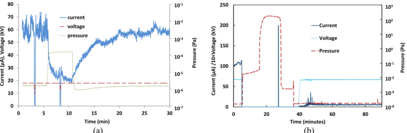
Another important result of this work was the observation of the dynamics of the field emission current in response to changes in residual gas pressure. As seen in Fig. 4(a), field emission is observed to return to its original value with a time constant on the order of 5 minutes. More details of these experiments and a discussion on possible physical mechanisms can be found in [21].
Analysis of the WC tip with a scanning electron microscope showed that growth of a pre-existing micro protrusion has occurred after exposure to an electric field. Energy dispersive X-ray analysis showed that such structures are mainly made of carbon [5].
These results led to changes in the bushing experiments at IRFM and led to the idea of using glow discharge at higher pressure in order to bombard the cathodic emission sites. As seen in Fig. 4(b), field emission current was shown to be diminished by about 90% by a 10 second glow treatment at 0.2mA glow current in argon. Field
0 0.5 1 1.5 2 2.5 0 50 100 150 200 250 Tot al calcu la ted ion flu x (n A) Emission cu rr en t (µA) Pressure (Pa) N2 emission H2 emission He emission Ar emission N2 ionic H2 ionic He ionic Ar ionic 10-1 10-4 10-3 10-2 100 10-5 10-6 00.511.522.5050100150200250
Total calculated ion flux (nA)Emission current (µA)
(a) (b)
FIGURE 4. (a) Dynamics of gas pressure effect on field emission include a return to the original intensity after pumping down.
(b) Reduction of field emission before and after cathode exposure to argon glow discharge. The glow current was 0.2mA for a duration of 10 seconds, visible at about 28 minutes in the experiment.
emission before the glow treatment was of the order of 100µA as seen in the figure, after which point the secondary pump was turned off and gas was injected. The glow treatment was of a short duration, and is visible as a 200µA current peak at around 28 minutes experiment time. After pumping down and applying the same voltage as before the glow treatment, field emission current was observed to be dramatically reduced, and to be relatively stable at the new, lower value for over 20 minutes.
This work is complicated by the observation that breakdowns are observed in some experiments when the voltage is applied after the glow treatment. Breakdown likelihood was reduced by shorter glow treatment time in this work when compared to a series of experiments at other conditions (10-120 second glow treatment time, 0.2-2mA glow current). The investigation of the reason for breakdown is currently under investigation and may involve particulate matter created by sputtering during the glow treatment. Further studies will also be required to determine if these results, obtained on a small scale experimental setup limited to 30kV applied voltage, may be applicable to the larger bushing system.
Experiments on a Single Stage Test Bushing (IRFM)
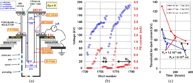
Figure 5(a) shows the design of the single stage bushing. It is integrated with a 100 liter vacuum tank that allows pumping, gas flow and pressure measurement. The electric fields shown have been calculated with a 3D electrostatic code (OPERA-3D [22]) for 200 kV applied voltage. The cathode is insulated and connected to ground through a µA meter, which allows the dark current to be measured directly. A cryo trap using LN2 was present to prevent pumping
oil vapors getting into the bushing, but this arrangement appeared ineffective. The base pressure was around 3x10⁻⁶ mbar.
Initially the anode corresponding to a 40 mm vacuum gap was mounted. Already at the lowest voltage that the power supply could provide (23 kV), dark current was present and gas was released by the system during the application of voltage. By gradually increasing the voltage the system was conditioned. In the end no more than 105 kV could be held, but it was found later that this was due to a problem in the connection between the power supply and the transmission line.
Then, the installation has been baked several times to 140 °C under vacuum for several days. This provoked a small leak over the Al joint between the vacuum tank and the cathode. In the end it was decided to live with it (P = 1.3x10⁻⁵ mbar for an estimated pumping speed of 10 l/s). No beneficial effect of the heating could be identified.
After the problem with the power supply was identified and repaired, conditioning reached quickly 140 kV. At this point significant dark current (I>1 mA) flowed between the electrodes. The dark current could be suppressed by injecting up to 0.15 Pa of He gas and 140-150 kV could be reached, but no more.
As Geeps-Centralesupélec had found that N2 is much more effective than He, this was tried next. Subsequent
conditioning then led the system to hold 185 kV with no dark current present (I<3 µA as measured by the µA meter), see Fig. 5(b) and 6(a). The maximum voltage reached was 191 kV for 0.5 seconds at 0.10 Pa N2 pressure.
Further progress could not be made because external breakdowns (visible flashes) appeared over the porcelain insulator, which was in air.
0 10 20 30 40 50 60 70 80 0 5 10 15 20 25 30 Pr ess ur e (P a) Curr en t (µA), V olt ag e (kV) Time (min) current voltage pressure 10-4 10-7 10-6 10-5 10-3 10-2 10-1 0 50 100 150 200 250 0 20 40 60 80 Pr ess ur e (P a) Curr en t (µA) /10 ×V olt ag e (kV) Time (minutes) Current Voltage Pressure 10-1 10-4 10-3 10-2 103 100 101 102
(a) (b) (c)
FIGURE 5. (a) The design of the single stage test bushing at IRFM. Dimensions are in mm. Anode and cathode are separated by
40 mm. (b) Part of the conditioning of this bushing: blue diamonds show the voltage in kV, red circles the power supply current in mA. (c) Evolution of the voltage threshold at which the dark current becomes observable with voltage-off time.
After each conditioning session, a certain voltage could be held in the absence of added gas with no dark current flowing at all, for example 84 kV. The next day this voltage is reduced, to say 64 kV, see Fig. 5(c). Waiting for a longer time, stopping the pumps or opening the vessel to air further reduces this voltage. Reconditioning is then needed to recover the previous performance. We attribute this phenomenon to a reduction in the cathode work function due to the adsorption of air, moisture, pumping oil, … , on the cathode metal surface, see eq. 1. This deconditioning phenomenon is faster if the base pressure is higher, as can be clearly seen in Fig. 5(c).
(a) (b)
FIGURE 6. (a) Voltage Vht (blue solid line) and power supply current Iht (red dotted line) vs. time for three pulses: 1765 no N2, no dark current; 1771 no N2, dark current; 1787 with 0.1 Pa N2. The distance between the electrodes was 40 mm. (b) Voltage and
power supply current for pulse 2008, electrodes separated by 25 mm, no N2.
Next, the cylindrical anode was replaced with a new one with a diameter of 159 mm, thus reducing the gap between the electrodes from 40 mm to 25 mm. The cathode and insulator remained the same. The cryo trap was removed and the air leak could be reduced to a base pressure of 5×10⁻⁶ mbar. Reconditioning was fast and, interestingly, the dark current was smaller at the same voltage. Thus, despite a 60% increase in electric field, the dark current was smaller than before, see Fig. 6(b). Also, after conditioning, a dark current threshold of 140 kV
could be reached, the same as with the 40 mm gap. Interestingly, external breakdowns over the insulator occurred at around 150 kV (visible flashes over the insulator) and 160 kV could not be reached.
DESIGN TWO-STAGE COMPACT BUSHING
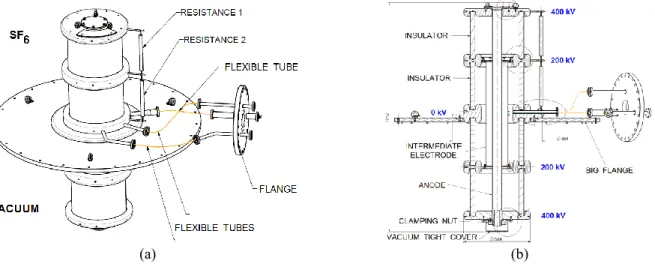
The bushing is made up of two 40 mm wide vacuum gaps, 3 cylindrical electrodes and 4 cylindrical porcelain insulators. The bushing is vacuum tight and there is a possibility to provide gas and pumping through the flexible tubes (Fig. 7). The two internal vacuum gaps communicate through apertures in the intermediate electrode. The structure rests on a vacuum tight “big flange”. Above this flange is SF6, below is vacuum. The intermediate voltage
is provided through a resistive divider inside the SF6.
The bushing concentrates the electric field in its interior. Provision of N2 gas to its interior will suppress the dark
current. Because the electric field diffusing into the vacuum tank will be lower, the dark current there should be lower or eliminated.
This bushing is presently being manufactured. Installation on the Cadarache MV testbed and subsequent testing will take place in 2017.
(a) (b)
FIGURE 7. (a) 3D view of the bushing. (b) Cut-through view of the bushing.
CONCLUSIONS
During the course of this work it has been experimentally observed (Geeps/LCAR) that a cathode exposed to an electric field can “grow” micro protrusions that are mainly composed of carbon, coming perhaps from vacuum pumping oil. Cracking and polymerization of hydrocarbons (which are mobile on the surface) could create such structures. Such micro protrusions then enhance the local electric field and strongly increase the dark current. Adding gas to the vacuum causes ion bombardment of the carbon protrusion and can ablate it. Thus an equilibrium between accumulation and ablation of carbon is established [5].
On the other hand, at IRFM it was established that exposure to air in the absence of an electric field decreases the voltage threshold at which the dark current becomes observable (Fig. 5(c)). It is hard to envisage the build-up of protrusions in the absence of electric fields and the thesis of a reduction of the cathode work function due to the adsorption of the air molecules is favored.
Therefore (at least) two processes appear to be involved in the production of dark current: (1) changes in the cathode geometry by the creation/destruction of (carbon) micro protrusions, (2) changes in the cathode work function by adsorption/desorption of gas.
Both processes will be active at the same time.
The ultimate goal of the HVIV project is the construction of a compact bushing, as described above. Its design is complete and at the time of the Conference the 2-stage bushing is under construction.
ACKNOWLEDGEMENT
This work benefited from financial support by the French National Research Agency (Agence National de la Recherche; ANR) in the framework of the project ANR-12-BS09-0013 (HVIV).
REFERENCES
1. A. Simonin, J. Achard, K. Achkasov, S. Bechu, C. Baudouin, O. Baulaigue, C. Blondel, J.P. Boeuf, D. Bresteau, G. Cartry, W. Chaibi, C. Drag, H.P.L. de Esch, D. Fiorucci, G. Fubiani, I. Furno, R. Futtersack, P. Garibaldi, A. Gicquel, C. Grand, Ph. Guittienne1, G. Hagelaar, A. Howling, R. Jacquier, M.J. Kirkpatrick, D. Lemoine, B. Lepetit, T. Minea, E. Odic, A. Revel, B.A. Soliman, P. Teste, R&D around a photoneutralizer-based NBI system (Siphore) in
view of a DEMO Tokamak steady state fusion reactor, Nuclear Fusion 55, 123020 (2015)
2. P. Massmann, D. Boilson, H.P.L. de Esch, R.S. Hemsworth and L. Svensson, Voltage holding and dark currents in
the Cadarache 1 MV ion beam facility, Proc. 20th ISDEIV conference, Tours, France, 2002, pp. 315 - 318.
3. W.T. Diamond, New perspectives in vacuum high voltage insulation. I. The transition to field emission, J. Vac. Sci. Technol. A16, 707 (1998).
4. R.G. Forbes, Simple good approximations for the special elliptic functions in standard Fowler-Nordheim tunneling
theory for a Schottky-Nordheim barrier, Applied Physics Letters 89, 113122 (2006)
5. M. Márquez-Mijares, B. Lepetit, D. Lemoine, K. Almaksour, M. J. Kirkpatrick, Ph. Dessante, E. Odic, D. Alamarguy, F. Bayle, Ph. Teste and F. Karlický, On the influence of ambient gas pressure and carbon adsorption on
dark current emission from a cathode, submitted to Journal of Vacuum Science & Technology.
6. High voltage vacuum insulation, basic concepts and technological practice, R. V. Latham Ed., Academic Press,
1995. ISBN 0-12-437175-2.
7. G. Blondiaux, M. Valladon, L. Quaglia, G. Robaye, G. Weber, and J.L. Debrun, Study of the growth of carbon on
targets during ion bombardment, Nucl. Instrum. Methods Phys. Res. Sect. Accel. Spectrometers Detect. Assoc.
Equip. 227, 19 (1984).
8. M. Márquez-Mijares, B. Lepetit and D. Lemoine, Carbon adsorption on tungsten and electronic field emission, Surface Science 645, 56 (2016)
9. B. Lepetit, D. Lemoine and M. Márquez-Mijares, Static electric field enhancement at nanoscale structures, Journal of Applied Physics 120, 085105 (2016).
10. G. Kresse and J. Hafner, Phys. Rev. B 47, 558 (1993) ; G. Kresse and J. Hafner, Phys. Rev. B 49, 14251 (1994) ; G. Kresse and J. Furthmüller, Comput. Mater. Sci. 6, 15 (1996) ; G. Kresse and J. Furthmüller, Phys. Rev. B 54, 11169 (1996).
11. L. Cranberg The Initiation of Electrical Breakdown in Vacuum J. Appl. Phys. 23, 518 (1952);
12. E.L. Murphy and R.H. Good Jr Thermionic emission, field emission, and the transition region Phys. Rev. 102, 1464-1473 (1956)
13. B Seznec, Ph Dessante, L Caillault, J-L Babigeon, Ph Teste, and T Minea Controlled electron emission and vacuum
breakdown with nanosecond pulses J. Phys. D: Appl. Phys. 49, 235502 (2016);
doi:10.1088/0022-3727/49/23/235502
14. P Teste and J-P. Chabrerie Some improvement concerning the modelling of the cathodic zone of an electric arc (ion
incidence on electron emission and the ‘cooling effect’) J. Phys. D: Appl. Phys. 29 697–705 (1996)
15. D. R. Lide, CRC Handbook of Chemistry and Physics ,Boca Raton, FL: CRC Press, 12–124 (2005)
16. W. B. Nottingham, Thermionic Emission from Tungsten and Thoriated Tungsten Filaments Phys. Rev., 49, 78 (1936).
17. F. M. Charbonnier, R. W. Strayer, L. W. Swanson, and E. E. Martin, Nottingham Effect in Field and T−F Emission:
Heating and Cooling Domains, and Inversion Temperature Phys. Rev. Lett., 13, 397 (1964).
18. L. W. Swanson, L. C. Crouser, and F. M. Charbonnier, Energy Exchanges Attending Field Electron Emission Phys. Rev., 151, 327 (1966).
19. R.W. Hockney and J.W. Eastwood, Computer Simulation Using Particles, Adam Hilger, Bristol, 1988; ISBN-10: 0852743920
20. B Seznec, Ph Dessante, T. Jager, L Caillault, Ph Teste, and T Minea Dynamics of microparticles in vacuum
breakdown: Cranberg’s scenario updated by numerical modeling Phys. Rev. Accel. Beams. (2016) – submitted
21. K. Almaksour, M. J. Kirkpatrick, Ph. Dessante, E. Odic, A. Simonin, H. P. L. de Esch, B. Lepetit, D. Alamarguy, F. Bayle, Ph. Teste, Experimental study of the reduction of field emission by gas injection in vacuum for accelerator
applications, Phys. Rev. Accel. Beams 17, 103502 (2014)
22. Vector Fields OPERA-3D software, Cobham plc, Brook Road, Wimborne, Dorset, BH21 2BJ, UK. http://operafea.com/