Concentrated solar power on demand
The MIT Faculty has made this article openly available. Please share
how this access benefits you. Your story matters.
Citation
Slocum, Alexander H., Daniel S. Codd, Jacopo Buongiorno, Charles
Forsberg, Thomas McKrell, Jean-Christophe Nave, Costas N.
Papanicolas, et al. “Concentrated Solar Power on Demand.” Solar
Energy 85, no. 7 (July 2011): 1519-1529.
As Published
http://dx.doi.org/10.1016/j.solener.2011.04.010
Publisher
Elsevier
Version
Author's final manuscript
Citable link
http://hdl.handle.net/1721.1/105409
Terms of Use
Creative Commons Attribution-NonCommercial-NoDerivs License
Concentrated Solar Power on Demand
Alexander H. Slocum1*, [email protected]
Daniel S. Codd1, [email protected]
Jacopo Buongiorno2, [email protected]
Charles Forsberg2, [email protected]
Thomas McKrell2, [email protected]
Jean-Christophe Nave3, [email protected]
Costas N. Papanicolas4, [email protected]
Amin Ghobeity1, [email protected]
Corey J. Noone1, [email protected]
Stefano Passerini2, [email protected]
Folkers Rojas1, [email protected]
Alexander Mitsos1, [email protected]
Abstract
A concentrating solar power system is presented which uses hillside mounted heliostats to direct sunlight into a volumetric absorption molten salt receiver with integral storage. The concentrated sunlight penetrates and is absorbed by molten salt in the receiver through a depth of 4-5 meters, making the system insensitive to the passage of clouds. The receiver volume also acts as the thermal storage volume
eliminating the need for secondary hot and cold salt storage tanks. A small aperture and refractory-lined domed roof reduce losses to the environment and reflect thermal radiation back into the pond. Hot salt is pumped from the top of the tank through a steam generator and then returned to the bottom of the tank. An insulated barrier plate is positioned within the tank to provide a physical and thermal barrier between the thermally stratified layers, maintaining hot and cold salt volumes required for continuous operation. As a result, high temperature thermal energy can be provided 24/7 or at any desired time.
The amount of storage required depends on local needs and economic conditions. About 2500 m3 of nitrate salt is needed to operate a 4 MWe steam turbine 24/7 (7 hours sunshine, 17 hours storage), and
with modest heliostat field oversizing to accumulate energy, the system could operate for an additional 24 hours (1 cloudy day). Alternatively, this same storage volume can supply a 50 MWe turbine for 3.25
hours without additional solar input. Cosine effect losses associated with hillside heliostats beaming light downwards to the receiver are offset by the elimination of a tower and separate hot and cold storage tanks and their associated pumping systems. Reduced system complexity also reduces variable costs. Using the NREL Solar Advisor program, the system is estimated to realize cost-competitive levelized production costs of electricity.
1
Department of Mechanical Engineering, Massachusetts Institute of Technology, Cambridge, MA 02139, US 2
Department of Nuclear Science & Engineering, Massachusetts Institute of Technology, Cambridge, MA 02139, US 3
The Department of Mathematics and Statistics, McGill University, Montreal, CA
H3A 2K6, CanadaDepartment of Mathematics, Massachusetts Institute of Technology, Cambridge, MA 02139, USA 4
The Cyprus Institute, Nicosia 1645, CY *To whom correspondence should be addressed.
Keywords:
concentrating solar power, molten salt, volumetric absorption receiver, hillside heliostats, thermal storage Abbreviations:
CSPonD Concentrated Solar Power on Demand Symbols: α attenuation coefficient δ optical thickness ε emissivity φ beam-down angle θi incident angle θt transmitted angle θr reflected angle D diameter Io incident intensity I transmitted intensity n index of refraction R reflection coefficient
1. Background
A robust solar energy portfolio is likely to include solar thermal systems that enable energy storage with electricity production when there is limited sunlight. Concentrating Solar Power (CSP) systems that use a central receiver with integral thermal energy storage have the potential to produce 24/7 base load and/or peak electric power. Power towers use heliostats to focus sunlight on a receiver placed atop a tower to reduce heliostat shadowing, increase optical efficiency, and to achieve high solar flux concentration and steam plant efficiency (Viebahn et al., 2008). Conventional high temperature CSP systems have evolved to use a central tower where a heat transfer fluid circulates through tubes onto which the sunlight is focused. However, maximum allowable fluxes are limited to avoid thermal degradation of the receiver tubing. Lata et al. (2008) cites the tradeoffs between tube diameter, wall thickness, receiver durability and pressure drop in conventional tubular receiver designs while describing an external tubular receiver capable of achieving slightly higher maximum fluxes, up to 1.0 MW/m2, thereby reducing receiver surface area and losses while increasing overall plant efficiency.
Utilizing molten salts as the working fluid enables simple subsequent thermal storage, due to their high heat capacities and wide operating temperatures. Unfortunately, daily receiver filling requires
ancillary heaters and presents additional risks should the salt freeze, requiring electric heat tracing on long piping runs, valves and manifolds. Despite these measures, operating problems still occur; for example, the Solar Two CSP demonstration plant was disabled by frozen salt in pipes (Reilly and Kolb, 2001). Another approach is direct absorption of sunlight by several-centimeter thick salt waterfalls, but the cost of pumps, manifold and piping preheaters, and fluid flow variations as a function of varying solar flux, limited the practicality of such systems (Bohn, 1987).
To minimize receiver fluid pumping losses and enable alternative receiver designs, Rabl (1976) proposed a beam-down reflective tower with a ground-based CSP receiver. Similarly, Yogev (1997) and Epstein (1999) suggested a beam-down system where the light was to be beamed directly into a molten salt/metal filled container. It has even been proposed for tall buildings to use balcony-mounted heliostats to direct sunlight to a receiver placed atop the building (LeBarre, 2010). Since Rabl’s proposal in 1976,
significant experimental work has occurred on beam-down towers and ground receivers, especially for reforming materials (Yogev et al., 1998; Segal and Epstein, 2003). The Odeillo solar furnace facility uses a north facing parabola focused on a target built into one wall of a building that holds offices and
laboratories. 63 south-facing flat mirror heliostats track the sun's movement and focus it down on the north facing parabola (Trombe and Le Phat Vinh, 1973). NREL also has a high-flux solar furnace system where heliostats aim light towards a ground-based secondary reflector system that redirects and
concentrates the sunlight to a small aperture receiver, although up to 10% of the energy is lost with each reflection (Skinrood et al., 1974). These systems achieve high concentrations and receiver temperatures with large, precision secondary optical elements – whose cost has prevented the commercial adoption of beam-down CSP.
Conventional thermal storage systems require two molten salt storage tanks, each capable of storing the entire system volume (Herrmann et al., 2004). In traditional CSP systems, cost-savings have been obtained with single tank systems relying on temperature stratification via natural thermocline formation (Pacheco et al., 2002). Copeland et al. (1983; 1984) has shown “rafted thermocline” designs effective at boosting thermal stratification in water tanks, with suggested designs for molten salt thermal storage tanks. However, passive rafted thermoclines would rely on two parameters difficult to control in high temperature molten salt tanks: maintaining neutral buoyancy at the hot-cold thermocline interface; and a near perfect seal with the side walls to prevent leakage around the divider raft. Indeed, tests performed in water showed the neutrally buoyant raft design may display instabilities and tilt and/or jam in the storage tank. Demonstration CSP plants without storage have typically been designed with a co-firing gas turbine scheme to enable continued operation when the solar system is down (European Commision, 2005).
2. CSPonD: Collocated receiver and storage system
Here we present a new system with heliostats mounted on a hillside that beam light directly into an open container of molten salt at the base of the hill, or into a one-bounce system with the receiver at the top of the hill (Fig. 1). A small aperture in the receiver lets the sunlight penetrate the surface of the large molten high temperature salt pond. Volumetric absorption enables a simpler receiver design with a free surface molten salt pond, without high-pressure, high-flow molten salt pumps, capable of high temperature storage. The molten salt surface is self-healing – tolerating high solar flux transients without irreparable sudden or cumulative damage to the receiver. Concentrated Solar Power on Demand
(CSPonD) could provide 24/7 power and thus help fill a critical need in solar power, that of energy storage (Slocum et al., 2010). Incoming concentrated solar flux directed at the aperture can follow one of three paths: refracted into the molten salt; reflected off the salt surface towards the inner surface of the receiver lid; or directly impinged on the inner surface of the lid (Fig. 2). An important design goal is to shape the cover to function as a diffuse reflecting concentration booster, not unlike the compound parabolic concentrator units used in beam down towers (Bassett and Derrick, 1981; Derrick and Bassett, 1985).
For the near term we consider a salt commonly used in CSP plants: sodium-potassium nitrate (e.g., Hitec® solar salt: 60/40 wt% NaNO3-KNO3) which has a low melting point of 222
o
C. Although above 593oC solar salt decomposes and becomes corrosive and dangerous, systems have been built and operated to pump it between hot and cold storage tanks and a steam generator (Herrmann et al., 2004). The power block, including salt pumps, heat exchanger/steam generator & power generation device, for a nitrate salt based CSPonD system will be very similar to those that can be commercially obtained. Hence, for a near term CSPonD system, a steam power cycle will be assumed with peak steam temperatures of 500-540°C.
Both the molten salt pond and the lid will exchange heat with each other and to the environment by radiation, convection and conduction; the primary heat transfer mechanism is through radiation. The system cover will be lined with refractory firebrick and backside cooled, so the salt vapor rises and
(A) Beam-down (B) Beam-up
Fig. 1. Representative CSPonD sites in White Sands, NM for pond receiver without (A) and with (B) secondary
reflector. The CSPonD system simultaneously collects sunlight while also acting as the beam-down optic thereby reducing overall system complexity and cost. Icons illustrate receiver location and discretized terrain sampling locations from elevation data, not an actual heliostat layout. See Noone et al. (2011).
collecting on evaporator coils within a refrigerator. The resulting white surface will grow until the thickness results in a thermal resistance that condenses the salt vapor, but the surface continually melts and returns liquid salt to the pond. The liquid/solid interface is expected to act as a diffuse reflector to incoming light that reflects off the surface of the salt. Solidified salt has a very high reflectivity in the visible spectrum and behaves nearly as a Lambertian reflector; liquefied salt will be subject to grazing-angle Fresnel surface reflections and as such, much of the light impinged onto the lid will be reflected back to the pond. The energy that is transferred to the lid is from lower-temperature, longer wavelength radiation from the salt surface. Only a small fraction of incoming photon energy is converted to thermal energy at the lid.
The vapor pressures of molten salts are fairly low, on the order of 0.001 bar for chloride salts at 900°C. As a result, the overall fuming rate is low, given as 0.2 kg per square meter of exposed salt area per hour for a chloride salt bath at 870°C (ASM, 1991). For the 5 m deep x 25 m diameter system proposed in the following text, this equates to roughly 100 kg/hr, or less than 0.06% of the entire salt mass. Lower temperature nitrate CSPonD systems will have lower salt vapor pressures and mass transfer, and reduced radiative transfer between the salt surface and the lid as compared to higher temperature chloride salt systems. The lid is not depending on mass transfer for cooling – active cooling will be employed to obtain the desired lid operating temperature. Cooling loops would be concentrated in high heat flux regions, and various zones can be employed for temperature control throughout the lid. It may be found that the optimal lid design is not isothermal, but has varying temperature to limit radiative transfer and convective losses. The collected cover energy, unique to CSPonD systems, can vary from 2-20% of the incident solar power and this intermediate-temperature heat is used elsewhere in the plant (Ghobeity et al., 2010). The percentage of lid heat extracted depends primarily on the plant layout: hillside topology, operating temperatures, and seasonal and diurnal position of the sun. In a dual-purpose desalination and electricity production plant using the CSPonD concept, heat collected by the cover can be used for preheating feed water to the steam generator or desalination feed water (Goosen et al., 2002; Ghobeity and Mitsos, 2009; Ghobeity et al., 2010).
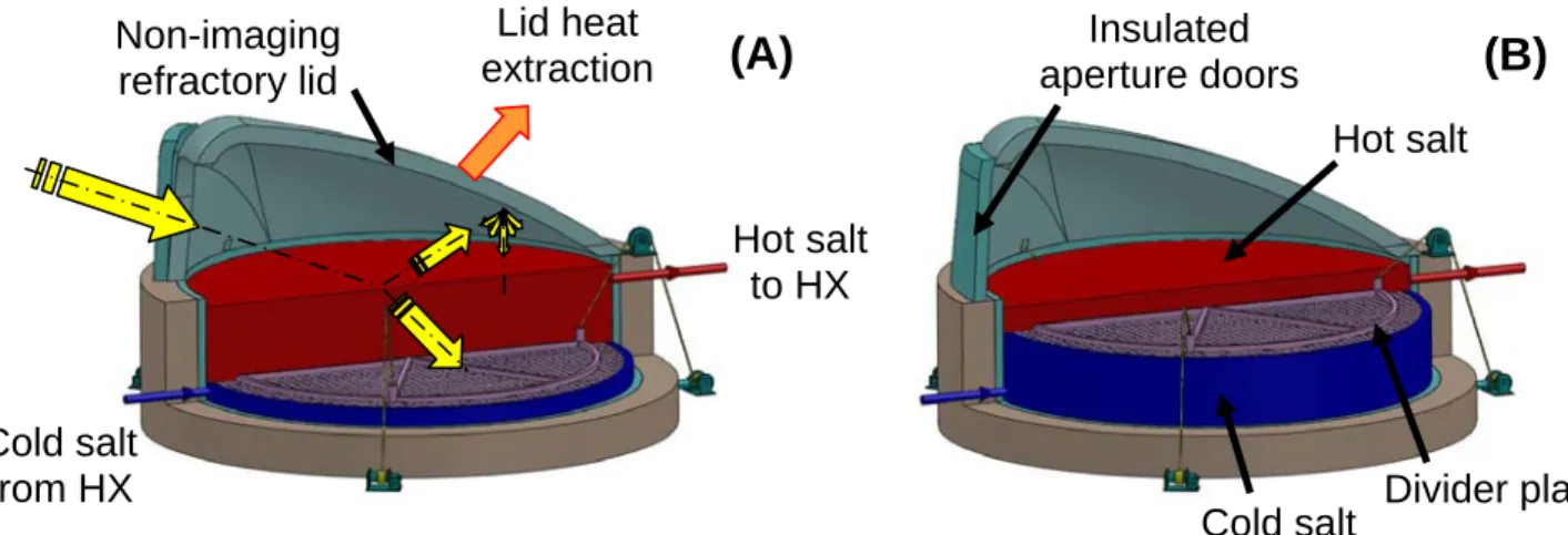
Fig. 2. Cross sections of a CSPonD volumetric absorption molten salt receiver/storage system: (A) Yellow arrows
denote light path within receiver. At end of a sunny day the divider plate has moved down and the hot salt region is fully charged. (B) Whereas after prolonged heat extraction without solar input, the divider plate has moved up and the cold side is full. Hot molten salt is pumped as needed from the top of the tank to provide reasonably constant power and temperature input to a steam generator or other power cycle. Colder, yet still liquid salt from the steam generator is returned to the bottom of the tank.
The top surface of the salt needs to remain at a constant level for consistent solar absorption; hence, the tank is split into two zones with a moving barrier plate. The top zone is the hot salt side, and the bottom zone is the cold salt side. An insulated creep and corrosion resistant alloy plate divides the two sides, providing a physical and thermal barrier between the thermally stratified hot and cold layers within the tank. The light will penetrate deeply and a small fraction of it will impact the highly absorbing divider plate causing convection currents, heating the hot side to a uniform high temperature (Fig. 2). The near neutrally buoyant divider plate is moved axially by small actuators, with negligible power consumption, to maintain the hot and cold salt volumes required for continuous operation. As a result, high-temperature salt can be provided even as the average temperature in the tank decreases (Fig. 3).
As the divider plate is lowered when the aperture is open and the tank is being heated by sunlight, colder salt from below moves past the annular clearance space between the barrier plate and tank wall to be reheated. Relative “blow-by” salt velocities are slow (much less than 1 cm/s for a nominal 20 cm annular clearance on the proposed system), accounting for the daily downward motion of the plate displacing fluid and pumped cold salt returning from the heat exchanger. Semenyuk (1983) describes a means to calculate exergy losses for mixing two working bodies differing only in temperature. For a nitrate CSPonD receiver with hot salt at 550C, cold salt at 250C and ambient temperature of 300 K, the exergetic mixing efficiency (1 = no loss) is found as 0.935; this value approaches 1 for higher
temperature CSPonD systems. Mixing losses are incorporated in the worst case estimates of receiver efficiency listed as 0.6 in Table 2.
The salt-filled annular clearance between the loose fitting divider plate and tank walls acts as a buffer by limiting thermal gradients as the divider plate moves. Degradation of the tank walls due to thermal shock is reduced compared to well-sealed barrier thermoclines with sharp thermal interfaces (Copeland et al., 1984). The tank is internally insulated with mortarless insulating refractory brick, whose thermal resistance and mass limits temperature swings at the mild steel tank shell, as depicted in Fig. 4 (Kolb, 1993). If needed, a thin corrugated alloy liner can be employed which minimizes thermal shock and reduces erosion and spalling of the refractory brick in the tank; this internally-insulated design has
Hot salt
Cold salt
Divider plate
Non-imaging
refractory lid
Lid heat
extraction
Insulated
aperture doors
(A)
(B)
Hot salt
to HX
Cold salt
from HX
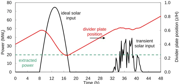
Fig. 3. Simplified divider plate position example for two day/night cycles: Ideal solar input (left) and transient, or
cloudy, solar input (right) for a constant 20MWt extraction system.
0.0 0.2 0.4 0.6 0.8 1.0 0 10 20 30 40 50 60 70 80 0 4 8 12 16 20 24 28 32 36 40 44 48 Divider plate position (z/H) Power (MW t ) Time (h) divider plate position transient solar input ideal solar input extracted power
been shown to be more cost-effective than a stainless steel tank with external insulation (Gabbrielli and Zamparelli, 2009). Metallurgical salt baths have proven commercial “super-duty” alumina/silica or pure silica fireclay bricks adequately resist corrosion from molten nitrate or chloride mixtures (ASM, 1991). Recent tests have verified the cyclic stability of silica particles in molten sodium and potassium nitrate at the temperatures considered (Brosseau et al., 2005).
Two 90 degree arcs of heliostats with radius 390 meters feeding two apertures on a volumetric molten salt receiver 25 m diameter and 5 m deep containing 4500 tons (2500 m3) of 550oC molten nitrate salt could power a 4 MWe steam turbine continuously, 24/7 (7 hours sunshine, 17 hours storage) on a
daily basis. In addition, the heliostat field is sized so that for every 10 days of full sun, the system could also run for an addition 24 hours on a cloudy day (Table 1). Conservatively, one can assume it takes about 16 m3/MWe/hr of nitrate salt for non-sunshine operation. The CSPonD system is rated by continuous
power production, not peak power as is typical of traditional CSP systems without overnight storage. Greater power cycle efficiencies can be realized with the use of larger steam turbines. This can be accomplished with larger CSPonD receivers or several smaller units feeding a common power block. However, many locales will favor the use of CSP-generated power for peaking purposes, with greatly reduced storage needs. As such, the same 2500 m3 storage volume can supply a 50 MWe turbine for 3.25
hours without additional solar input. After peak demand subsides, heat extraction can be stopped and nighttime losses from the well-insulated receiver are minimal.
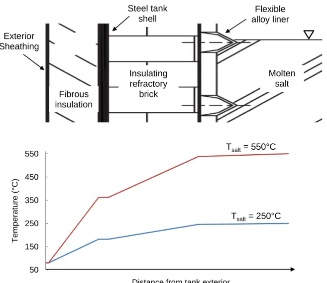
Fig. 4. Tank wall insulation schematic. Internal insulating refractory brick is used to reduce temperature
fluctuations at the tank shell. A thin, thermally conductive alloy liner can be employed to reduce axial thermal gradients and shock. Cross-section adapted from Kolb (1993) and Gabbrielli and Zamparelli (2009).
50 150 250 350 450 550 Temperature (°C)
Distance from tank exterior
Fibrous
insulation
Molten
salt
Flexible
alloy liner
Steel tank
shell
Exterior
Sheathing
Insulating
refractory
brick
T
salt= 550°C
T
salt= 250°C
The receiver’s “capture efficiency” can be defined as the fraction of incoming energy retained by the receiver – used to heat both the pond and the lid. Aperture size is driven by system sizing and input flux concentration and is used to calculate geometrical view factors and radiative losses to the
environment. Other losses include conduction though the tank walls and convection to the outside environment. In general, capture efficiency increases with input flux concentration as the system geometry approaches that of a blackbody. The self-healing nature of the molten salt surface tolerates much higher fluxes than conventional tube based receivers – and can achieve higher efficiencies as heliostat field technology and achievable concentration improves.
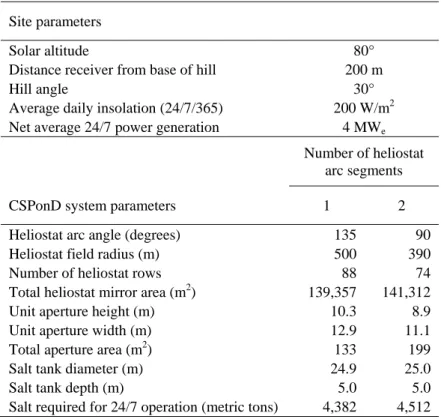
Table 1. Design parameters for 4 MWe 24/7 nitrate salt CSPonD system with either two 90° arc segment
heliostat fields and two apertures or a single 135° arc segment heliostat field and a single aperture.
Site parameters
Solar altitude 80°
Distance receiver from base of hill 200 m
Hill angle 30°
Average daily insolation (24/7/365) 200 W/m2 Net average 24/7 power generation 4 MWe
Number of heliostat arc segments
CSPonD system parameters 1 2
Heliostat arc angle (degrees) 135 90 Heliostat field radius (m) 500 390
Number of heliostat rows 88 74
Total heliostat mirror area (m2) 139,357 141,312 Unit aperture height (m) 10.3 8.9
Unit aperture width (m) 12.9 11.1
Total aperture area (m2) 133 199
Salt tank diameter (m) 24.9 25.0
Salt tank depth (m) 5.0 5.0
Salt required for 24/7 operation (metric tons) 4,382 4,512
High lid temperature leads to reduced capture efficiency due to large radiative and convective losses out of the aperture. However, a higher lid temperature reduces radiative exchange from the salt pond to the lid – effectively keeping more energy in the salt. For example, a 240°C lid and 550°C salt temps (ε ~ 0.9), roughly 18 kW/m2 is lost from the salt surface to the lid, 14% of the incoming power when the aforementioned receiver is “on sun” at the design point. With the aperture closed for 16 hours, salt-lid radiative transfer would result in nearly 140 MWh of energy transferred to the roof - nearly one-quarter of the 600 MWh (equivalent to 180 MWh electric at ηth = 0.30) storage capacity. This upper
bound assumes a fully-exposed salt surface and a constant salt surface temperature. However, high solar concentration enables reductions in exposed salt surface area, further reducing losses and heat gain from the salt to the lid. Also, the pond free-surface will cool due to radiative, as well as internal convective heat transfer while off-sun. As a result, permanent heat transfer from the pond to the lid will decrease.
Additionally, if energy was not extracted from the lid at a sufficient rate, the lid temperature will increase. Low lid thermal mass will result in quicker heat up and reduced nighttime losses. One possible
operational strategy would be to slow or stop lid heat rejection towards the end of the day while still on sun, allowing the lid temperature to equilibrate with the salt, reducing radiative transfer. Permanent heat transfer losses are incorporated into the receiver efficiency estimates (0.6-0.9) in Table 2 for the
continuous operation CSPonD system examined (i.e., both salt and lid heat rejection running 24/7). Similarly, large beam down angles (i.e., steeper hillsides) are effective at directing more of the incoming energy into the salt. A steep beam down angle has two effects: the illuminated or projected area of the aperture on the horizontal molten salt pool is decreased, reducing exposed salt area and subsequent losses; and Fresnel reflections off of the salt surface to the lid are reduced. To avoid hot spots and minimize system complexity, natural convection within the salt is needed. This can be designed into the pond using numerical methods (Nave, 2004). Preliminary results using the full variable-property
Navier-Stokes equations to produce direct numerical simulations show thermal gradients can be used to create plumes to mix the salt.
The CSPonD system could likely support higher power cycle temperatures should the need arise in the future. Future generation NaCl-KCl CSPonD designs could be considered for high temperature operation and the two zone tank could still be used. Most of the salt handling and power-cycle technology required for a hot chloride salt option for CSPonD has been partly developed for the molten salt nuclear reactor program (Forsberg et al., 2007). Liquid salt pumps have been tested up to 6,000 L/minute at temperatures exceeding 700°C (Grindell et al., 1960; Williams, 2006). Multiple CSPonDs could feed a common central power plant (Forsberg and Moses, 2009).
With regard to the stability of the salts, there is a large industrial experience base with molten salts used in the heat treatment of metals (Mehrkam, 1967; ASM, 1991). These high temperature salt baths are open to the atmosphere as metal components are moved in and out of the salt bath (Fig. 5). The heat treating industry has developed standard methods to test the salt, using additives to control salt chemistry, and replacing the salt if the impurity levels are too high. The rate of impurity buildup will be much lower for CSPonD than for a heat treating bath with its daily throughput of steel parts.
The use of quartz windows was considered to help reduce radiation losses and eliminate mass transfer across the aperture. However, as mentioned in literature and as observed in our testing, quartz crucibles in contact with many salts tend to lose their optical clarity with time (Li and Dasgupta, 2000). The salts chosen as appropriate for CSPonD systems have limited toxicological and environmental effects should some condense outside the receiver; however, any system which regularly loses heat transfer fluids (other than steam) to the environment will likely be denied a permit. Fortunately, the salt bath heat treating industry provides guidance. Salt bath furnaces employ ventilation hoods, either offset from the salt surface or directly overhead to capture salt fumes at their source. The salt vapors are drawn into the intake, and condense on the intake plenum. The accumulated salt is scraped off during routine
maintenance. A similar system can be installed above the aperture of the CSPonD receiver, perhaps utilizing an intake plenum with an automated salt scraping and collection system. Salt vapor and thermal losses can also be mitigated with the use of air curtains installed across the aperture (Paxson, 2009).
Fig. 5. Open air NaCl-KCl Salt bath at 900oC for metal heat treating. (Picture taken at Metallurgical
2.1 Volumetric absorption in molten salts
The light attenuation characteristics of the molten salt are critical as they strongly affect
temperature gradients within the salt and overall system design. For example, if the salt is too attenuating, in large deep ponds created for a large amount of storage, forced circulation of the salt could be required to prevent oveheating of the top surface of the salt. Conversely, if the salt is found to be too transparent, oveheating of the divider plate could occur if it is brought too close to the surface. The attenuation of the salt could be increased with the addition of nanoparticles to the salt, or conversly, impurities that build up with time could affect the behavior of the salt. The attenuation characteristics of the CSPonD candidate molten salts are currently not available. Accordingly, the efforts undertaken to obtain this data are detailed here.
2.1.1 Attenuation measurements in molten salt
Light attenuation in a semi-transparent medium is described by the attenuation (or extinction) coefficient, α (cm-1
), which represents the probability per unit length that a photon will be removed from the incident beam, either by absorption or scattering (Passerini, 2010). The attenuation coefficient depends on the photon energy, or wavelength, and also on the temperature of the medium. The intensity transmitted through a layer of material of thickness δ is related to the attenuation coefficient by the following equation:
αδ −
= eI
I 0 (1)
where I and I0 are the transmitted and incident intensities, respectively. Equation (1) can be used to
calculate the attenuation coefficient by measuring the intensity of light transmitted through known depths of a molten salt.
A furnace-based apparatus was designed and built to measure optical properties of a number of candidate molten salts at various temperatures and wavelengths (Passerini, 2010). It is capable of operating from room temperature up to 1,100oC. The apparatus and method were validated against published data by comparing results obtained for deionized water at room temperature and Hitec® salt1 from 250 to 500°C (Drotning, 1978; Smith and Baker, 1981). Due to the light signal intensity distribution, reliable data were obtained between 400nm and 800nm, while for shorter and larger wavelengths the signal to noise ratio drops significantly, making quantitative evaluation of the attenuation coefficients impossible
For illustrative purposes, the measured attenuation coefficient of a 60/40 wt% sodium-potassium nitrate mixture at 350°C has been applied to the reference solar irradiance plot of ASTM G173-03. Fig. 6 shows the result of applying the measured attenuation to this reference solar spectrum for different molten salt depths. At a depth of two meters, 93% of the total solar energy is absorbed by the candidate nitrate salt in the 400-800 nm range. It is important to note that 55% of the terrestrial solar insolation lies in the 400nm-800 nm range. Extrapolation of this data beyond the 400-800 nm range is difficult. However, it is expected that highly absorbing regions would be in the infrared region at wavelengths greater than 2.5μm, where the solar irradiance expires. Accordingly, some first order extrapolation could be performed.
1
Fig. 6. Solar irradiance attenuation for different molten salt depths. This figure was produced using experimentally
measured attenuation coefficients for a 60/40 wt% sodium-potassium nitrate mixture at 350°C in the wavelength range of 400-800 nm, the range where experimental measurements are possible.
0 0.2 0.4 0.6 0.8 1 300 600 900 1200 1500 1800 2100 2400 Normalized Irradiance Wavelength (nm) Reference: AM1.5 0.25 m Salt Depth 0.75 m Salt Depth 1 m Salt Depth 2 m Salt Depth 3 m Salt Depth
2.1.2 Irradiance distribution in receiver
For a central heliostat located on the optical axis of the receiver aperture, the input flux will be restricted to an ellipse of major axis Di projected on the salt surface, calculated as
φ sin / a i D D = (2)
where Da is the aperture diameter and φ is the nominal beam-down angle measured from horizontal. A
portion of the incoming concentrated light is reflected off the molten salt-air interface. This reflected fraction can be calculated from the Fresnel equations describing light as it moves between media of different refractive indices. The reflection coefficients for s- and p- polarized light are
2 ) sin( ) sin( ⎥ ⎦ ⎤ ⎢ ⎣ ⎡ + − = i t i t s R θ θ θ θ (3) 2 ) tan( ) tan( ⎥ ⎦ ⎤ ⎢ ⎣ ⎡ + − = i t i t p R θ θ θ θ (4)
The angles that the incident, reflected and refracted rays make to the normal of the interface are given as θi, θr and θt, respectively, and related by Snell’s Law and the law of reflection.
i air t salt n n sinθ = sinθ (5) i r θ θ = (6) where φ θi = 90°− (7)
Since the incident light is unpolarized, containing an equal mix of s- and p-polarizations, the reflection coefficient, R, is
(
Rs Rp)
/2R = + (8)
Equation (8) can be used to find the percentage of the incident energy which is reflected onto the lid. For the sample case of nitrate solar salt with φ = 20° and nsalt = 1.413 (Bloom and Rhodes, 1956), 84.7% of
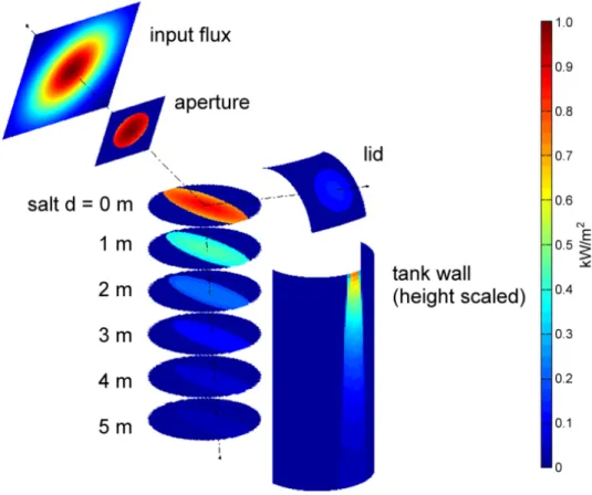
the incoming radiation refracts into the salt while 15.3% reflects onto the lid. The intensity of the refracted light at various salt depths is then found with Equation (1). Fig. 7 illustrates the incoming solar irradiance distribution for a centralized heliostat aimed at the receiver, simulated using MATLAB. An entire heliostat field array can be aimed to create a circular illumination distribution on the salt surface; much of the incoming radiation will be absorbed near the top of the salt surface and towards the rear of the tank. Hence, it is logical to extract high temperature salt in this location for the power cycle.
Fig. 7. Representative solar irradiance distribution for a single heliostat aimed at a CSPonD receiver. A complete
2.1.3 Solar simulator testing of a volumetric salt receiver
To test the CSPonD concept, a high-flux large-area solar simulator was designed to achieve output fluxes greater than 60 kW/m2 (Codd et al., 2010). Tests were conducted on a small scale receiver tank equipped with a movable divider plate, designed to partition the volumetric molten salt receiver into two thermally separated regions (Fig. 8).
The divider plate provides excellent thermal separation between the hot upper and cold bottom sections. The bare stainless steel top surface of the divider plate absorbs much more energy than the relatively transparent salt; as a result, the hottest region of the receiver is the top surface of divider plate. This creates natural convection cells in the top region thereby preventing overheating of the top surface and maximizing thermal storage in a given volume of salt. Fig. 9 depicts the convection currents within an alternate test receiver detected with a lab-built particle image velocimetry (PIV) system. Indeed, the light penetrating the salt causes heating deep within the sample and convective mixing readily occurs to prevent hotspots.
Due to packaging constraints, the small-scale divider plate testbed utilized a ¼” (6.35 mm) rigid silica insulating board affixed to the underside of the stainless steel divider plate. Full scale systems would utilize significantly more insulation, on the order of 10-20 cm, providing a greater thermal
resistance and limiting heat transfer while providing the design value of 300 K across the divider plate. In a larger and deeper system, the upper surface of the divider plate will receive less radiation than this small scale experiment. However, with full-scale insulation on the divider plate, conduction through the bottom plate will decrease. It is expected that natural convection into the upper hot salt region will remain of the same magnitude, and a temperature inversion should occur in the hot salt region – accordingly the Nusselt number will remain similar to this experiment. Regrettably, the 60-sun solar simulator was not capable of heating the salt above 380°C. This was to be expected with high conductive, surface radiative and convective losses for this low-flux test receiver. Full scale systems will utilize much greater flux levels and have significantly reduced system losses, which will increase the hot salt temperatures and the temperature difference across the divider plate.
However, these small scale experiments cannot provide insight to how a full scale machine would truly work. Hence, numerical modeling is required to design the full scale tank and divider plate system, and then testing of a deep tank system.
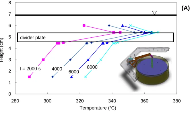
Fig. 8. Temperature distribution of CSPonD receiver optically heated by the 10.5 kW MIT CSP Solar Simulator;
inset depicts stainless steel (type 316L, 28 cm inner diameter x 8 cm high, 7 L solar salt capacity) test receiver. The movable divider plate (3.2 mm thick stainless steel disc with a 6.4 mm thick layer of rigid silica insulation board affixed to the underside) and is denoted by the shaded grey box located near the salt surface (A) and tank bottom (B) of the test receiver.
0 1 2 3 4 5 6 7 8 280 300 320 340 360 380 Height (cm) Temperature (°C) t = 2000 s 4000 6000 8000 divider plate 0.0 1.0 2.0 3.0 4.0 5.0 6.0 7.0 8.0 280 300 320 340 360 380 Height (cm) Temperature (C) divider plate t = 2000 s 4000 6000 8000
(A)
(B)
Fig. 9. Molten salt convection cell monitoring using PIV. Notice that there are particles in the molten salt that reflect
light which can be used to determine fluid movement within the receiver. The inset on the right is composed of two consecutive time frames (blue and green). The arrows show particles that have shifted from frame-to-frame; these can be used to characterize fluid movement.
2.2 Site selection and heliostat placement
There is precedence for the location of heliostats on a hillside to direct sunlight to a secondary reflector, then redirecting the power to a receiver on the ground (Trombe and Le Phat Vinh, 1973); however, up to 10% of the energy is lost with each additional reflection, not to mention high-flux secondary mirror cooling concerns, operation and installation costs. Meanwhile, there appears to have been a “land rush” for acquiring rights to flat, sunny land perceived to be needed for other types of solar power systems, which have increased the overall costs of traditional CSP systems. The system presented here thus reflects the solar energy from a heliostat field on a hillside directly into a receiver. In the northern hemisphere, a south-facing hillside field allows for direct beam-down entry into the molten salt pond as shown in Fig. 1a. These configurations allow for CSP collector fields to be built on otherwise undevelopable, steep terrain hence reducing system costs. Methods used by utility companies for emplacing utility poles on moderately steep terrain can be used for heliostat installation, and automated spray systems can be utilized for cleaning the mirrors. Indeed, one of our important conclusions is conventional power tower systems could benefit from hillside mounted heliostats. A numerical tool was developed to evaluate potential sites for beam up and beam down CSPonD configurations (Noone et al., 2011). For two case studies, White Sands, NM and China Lake, CA, the area investigated is roughly 10,000 km2 and optimal receiver locations for the beam-down configuration have efficiencies of 70% and 68%, respectively. In the beam-up configuration, both case studies have optimal receiver locations with efficiencies of 77%.. These efficiencies take into account cosine efficiency, shading and blocking losses due to the terrain; optical losses of the heliostats are not included in these results. However, "heliostat overall efficiency", given in Table 2 as 0.5-0.6, includes heliostat optical losses including reflectivity, mirror shape and tracking errors.
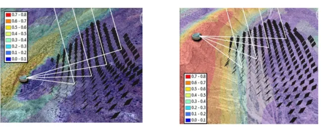
For each case study, one result is included to illustrate an optimal location for a pond receiver for each of two scenarios, (i) reflecting the sunlight up the hill into a secondary reflector at the receiver with an optical efficiency of 0.9, and (ii) reflecting the sunlight down the hill so as to not require a second reflection. Similar results were obtained for both sites, and a summary of the White Sands results are presented in Fig. 10.
Sites with highest efficiency from the White Sands area were shown in Figure 1. In these sites, the heliostat fields are north (right) of the receiver, represented in the image for visualization of the field extents only, not an actual heliostat layout. The field efficiency of the site with the secondary reflector is calculated to be 77% and the site without is 70%, a difference of 7% despite the 10% loss associated with the grazing angle reflection off the inner surface of the lid. Assuming that 15% of the land can be utilized, and of this land 30% is covered by heliostats, a solar-to-electric efficiency of 22%, and a 24/7 average solar insolation of 200 W/m2, the White Sands site could provide 20 GWe of power 24/7. Similar results
are obtained for China Lake.
(A) (B)
Fig. 10. Density overlay indicating areas of high efficiency CSPonD receiver sites in White Sands, NM: (A) beam
down and (B) beam up sites. Receiver locations corresponding to high annual average field efficiencies are in red and regions of poor efficiency in blue. Digital elevation data is from the Shuttle Radar Topography Mission (SRTM), with one arc-second resolution between elevation data points (SRTM1 v2.1), corresponding to roughly 30 meters on the topocentric plane (Farr et al., 2007). Due to the coarseness of the data, the analysis is regarded as a simplified model used for locating potential sites and approximating field efficiency. The instantaneous beam irradiation is calculated using version one of the Meteorological Radiation Model (MRM v1) for direct beam irradiance under cloudless skies (ERSI, 2008; Google, 2010).
2.3 Economics
The uncertainty associated with new technologies is very large and therefore a conservative as well as an optimistic economic analysis was conducted. The Solar Advisory Model (SAM) by NREL was used along with the economic assumptions by US Department of Energy for Call DE-FOA-0000104 set for 2020, including some incentives (Sargent & Lundy LLC, 2003).
The optimistic scenario gives an economical levelized cost of 0.07 $/kWh, while a conservative estimate is currently prohibitively high with a value of 0.33 $/kWh (Table 2). It should however be noted that this figure is high compared to present fossil fuel costs, not necessarily high compared to
conventional CSP systems. The range of levelized energy cost clearly demonstrates the need for further research, in particular with regards to i) the detailed design of the pond and lid along with selection of salt and materials, ii) the best use of the land available via optimal placement of heliostats and iii) the optimal integration of the pond and lid with the power cycle (and potentially a cogeneration scheme).
Table 2. Upper and lower bounds for predicted CSPonD levelized cost of energy.
Property Units Conservative Optimistic
Rating and efficiencies (input)
Average specific direct normal radiation kW/m2 0.25 0.30
Nameplate capacity MWe 4.0 4.0
Heliostat overall efficiency MWt/MWt 0.5 0.6
Pond efficiency MWt/MWt 0.6 0.9
HX efficiency MWt/MWt 0.9 1.0
Power cycle efficiency MWe/MWt 0.3 0.4
Availability*Capacity factor*(1-Derate) 0.7 0.9 Capital cost (input). Excluding contingencies, tax and land which are included in SAM
Heliostat specific cost $/m2 215 150
Pond cost $MM 4.8 1.9
Heat exchanger cost $MM 0.2 0.1
Power block cost $MM 4.8 2.4
Utilities, piping, site work $MM 8.6 3.5
Operating costs $MM/yr 2.0 0.5
Calculated properties
Overall efficiency MWe/MWt 0.08 0.22
Direct normal radiation required MW 49.4 18.5
Heliostat area required m2 197,530 61,730
Heliostat cost $MM 42.5 9.3
Operation hours/yr 6,132 7,884
Yearly electricity produced GWh/yr 24.5 31.5
Capital cost $MM 61 17
SAM results $/kWh 0.33 0.07
3. Conclusions and Future Work
A CSP system with integral storage has been presented where hillside mounted heliostats direct sunlight into a volumetric absorption molten salt receiver either near the base of the hill where the sunlight can directly penetrate the salt, or at the top of the hill where the light is redirected off the lid of the receiver before it enters the salt. In both cases, salt vapor condenses on the inside surface of the lid to form a self-healing reflective surface.
The concentrated light penetrates and is absorbed in the receiver by molten salt through a distance of 4-5 meters which allows for high solar fluxes and is structurally insensitive to cloud cover transients that affect other CSP systems. The receiver has a relatively small aperture with lower secondary heat losses and avoids thermal fatigue associated with boiler tube-type receivers while achieving high temperatures needed for efficient power generation. In addition, the receiver volume also acts as the thermal storage volume. Hot salt is pumped from the top of the tank through a heat exchanger and then back into the bottom of the tank. An insulated plate provides an additional thermal barrier between the thermally stratified hot and cold layers within the tank, and the barrier is moved axially up and down to provide high temperature thermal energy even as the average temperature of the salt in the tank decreases
Fundamental measurements of the optical absorbance properties of molten salt sand bench level experiments indicate viability of the concept. Analysis of hillsides at two southwestern government land sites shows good potential for CSP system development. An economic analysis using NREL’s Solar Advisor program indicates a levelized cost of electricity of $0.07-0.33/kWh.
The next step in the research is to design a 20-100 kWt test receiver that has an aperture size to
receive light from a typical concentrating heliostat, so a commercial array can be easily modified and used without needing additional concentrating optics at the aperture. This receiver would, however, be designed with the full anticipated depth of a larger system, so the optical penetration and convective mixing properties anticipated for the MWe sized CSPonD system can be evaluated.
4. Acknowledgements
This work is part of an interdisciplinary collaboration between the Cyprus Institute, the
University of Illinois at Urbana Champaign, the Electricity Authority of Cyprus, and the Massachusetts Institute of Technology. Generous graduate student fellowships were provided by the Chesonis Family Foundation and the Bill and Melinda Gates Foundation. The authors would also like to thank Prof. Jeffrey M. Gordon of Ben-Gurion University of the Negev and Dr. Steve Fantone of Optikos, Inc. for their optical engineering insights, and Prof. Alan Hatton of MIT for his evaluation of the viability of a nanoparticle-based approach to light absorption in molten salts.
References
ASM, 1991. ASM Handbook: vol. 4: Heat Treating, 10th ed. ASM International.
Bassett, I., Derrick, G., 1981. An upper bound on the efficiency of a cavity absorber. Optica Acta, Opt. Acta (UK) 28, 57-63.
Bloom, H., Rhodes, D.C., 1956. Molten Salt Mixtures. Part 2. The Refractive Index Of Molten Nitrate Mixtures And Their Molar Refractivities. The Journal of Physical Chemistry 60, 791–793.
Bohn, M.S., 1987. Experimental investigation of the direct absorption receiver concept. Energy 12, 227-233. Brosseau, D., Kelton, J., Ray, D., Edgar, M., Chisman, K., Emms, B., 2005. Testing of thermocline filler materials
and molten-salt heat transfer fluids for thermal energy storage systems in parabolic trough power plants. Transactions of the ASME. Journal of Solar Energy Engineering, Trans. ASME, J. Sol. Energy Eng. (USA) 127, 109-16.
Codd, D.S., Carlson, A., Rees, J., Slocum, A.H., 2010. A low cost high flux solar simulator. Solar Energy 84, 2202-2212.
Copeland, R., Green, J., 1983. Raft thermocline thermal storage, in: Proceedings of the 18th Intersociety Energy Conversion Engineering Conference, 21-26 Aug. 1983, Proceedings of the 18th Intersociety Energy Conversion Engineering Conference. AIChE, New York, NY, USA, pp. 1801-5.
Copeland, R., West, R., Kreith, F., 1984. Thermal energy storage at 900C, in: 19th Intersociety Energy Conversion Engineering Conference (Cat. No. 84CH2101-4), 19-24 Aug. 1984, 19th Intersociety Energy Conversion Engineering Conference (Cat. No. 84CH2101-4). American Nucl. Soc, LaGrange Park, IL, USA, pp. 1171-5.
Derrick, G., Bassett, I., 1985. Optimization of imperfect diffuse reflectors. Optica Acta, Opt. Acta (UK) 32, 313-28. Drotning, W., 1978. Optical properties of solar-absorbing oxide particles suspended in a molten salt heat transfer
fluid. Solar Energy, Sol. Energy (USA) 20, 313-19.
Epstein, M., Segal, A., Yogev, A., 1999. A molten salt system with a ground base-integrated solar receiver storage tank. Le Journal de Physique IV 9.
ERSI, 2008. ESRI Data and Maps, ArcMap v9.3 [GIS software].
European Commision, 2005. EUR 21615 SOLGATE - Solar hybrid gas turbine electric power system. Office for Official Publications of the European Communities, Luxembourg.
Farr, T.G., Rosen, P.A., Caro, E., Crippen, R., Duren, R., Hensley, S., Kobrick, M., Paller, M., Rodriguez, E., Roth, L., Seal, D., Shaffer, S., Shimada, J., Umland, J., Werner, M., Oskin, M., Burbank, D., Alsdorf, D., 2007. The Shuttle Radar Topography Mission [WWW Document]. Reviews of Geophysics. URL
http://www2.jpl.nasa.gov/srtm/
Forsberg, C.W., Moses, D.L., 2009. Safeguards Challenges for Pebble-Bed Reactors (PBRs): Peoples Republic of China (PRC) (No. ORNL/TM-2008/229). Oak Ridge National Laboratory (ORNL).
Forsberg, C.W., Renault, C., Le, B., Merle-Lucotte, E., Ignatiev, V., 2007. Les applications des sels liquides et les réacteurs à sels fondus= Liquid salt applications and molten salt reactors. Revue générale nucléaire 63–71. Gabbrielli, R., Zamparelli, C., 2009. Optimal Design of a Molten Salt Thermal Storage Tank for Parabolic Trough
Solar Power Plants. J. Sol. Energy Eng. 131, 041001.
Ghobeity, A., Mitsos, A., 2009. Optimal Use of Solar Thermal Energy for Combined Power Generation and Water Desalination, in: Proceedings of Distributed Renewable Energy Sources in the Mediterranean Region (DISTRES 2009). Presented at the DISTRES 2009, Nicosia, CY.
Ghobeity, A., Noone, C.J., Mitsos, A., 2010. Optimal Time-Invariant Operation of a Power and Water Cogeneration Solar-Thermal Plant. Solar Energy . Manuscript submitted for publication.
Google, 2010. Google Earth [WWW Document]. URL http://earth.google.com/
Goosen, M.F., Sablani, S.S., Al-Maskari, S.S., Al-Belushi, R.H., Wilf, M., 2002. Effect of feed temperature on permeate flux and mass transfer coefficient in spiral-wound reverse osmosis systems* 1. Desalination 144, 367–372.
Grindell, A.G., Boudreau, W.F., Savage, H.W., 1960. Development of Centrifugal Pumps for Operation with Liquid Metals and Molten Salts at 1100-1500 F. Nuclear Sci. and Eng. 7.
Herrmann, U., Kelly, B., Price, H., 2004. Two-tank molten salt storage for parabolic trough solar power plants. Energy 29, 883–893.
Kolb, G.J., 1993. Thermal cycling of thermal energy storage tanks proposed for the solar two central receiver power plant, in: ASME International Solar Energy Conference, April 4, 1993 - April 9, 1993, Solar Engineering.
Lata, J.M., Rodríguez, M., de Lara, M.Á., 2008. High Flux Central Receivers of Molten Salts for the New Generation of Commercial Stand-Alone Solar Power Plants. Journal of Solar Energy Engineering 130, 021002.
LeBarre, S., 2010. The Future of Green Architecture: A Live-In Power Plant. Popular Science July, 62-63. Li, J., Dasgupta, P.K., 2000. A simple instrument for ultraviolet-visible absorption spectrophotometry in high
temperature molten salt media. Review of Scientific Instruments 71, 2283.
Mehrkam, Q.D., 1967. An Introduction to Salt Bath Heat Treating. Tooling & Production June/July 1967. Nave, J.C., 2004. Direct Numerical Simulation of Liquid Films (Ph.D. thesis, UCSB).
Noone, C.J., Ghobeity, A., Slocum, A.H., Tzamtzis, G., Mitsos, A., 2011. Site selection for hillside central receiver solar thermal plants. Solar Energy in press.doi:10.1016/j.solener.2011.01.017
Pacheco, J.E., Showalter, S.K., Kolb, W.J., 2002. Development of a molten-salt thermocline thermal storage system for parabolic trough plants. Journal of Solar Energy Engineering 124, 153.
Passerini, S., 2010. Optical and Chemical Properties of Molten Salt Mixtures for Use in High Temperature Power Systems (SM thesis, MIT).
Paxson, A.T., 2009. Design and Validation of an Air Window for a Molten Salt Solar Thermal Receiver (SB thesis, MIT).
Rabl, A., 1976. Tower reflector for solar power plant. Solar Energy 18, 269-271.
Reilly, H.E., Kolb, G.J., 2001. An Evaluation of Molten-Salt Power Towers Including Results of the Solar Two Project. Sandia National Labs, Albuquerque, NM; Livermore, CA.
Sargent & Lundy LLC, 2003. Assessment of Parabolic Trough and Power Tower Solar Technology Cost and Performance Forecasts (No. SR-550-34440). NREL.
Segal, A., Epstein, M., 2003. Solar ground reformer. Solar Energy 75, 479-490.
Semenyuk, L.G., 1983. Exergy loss on mixing working bodies with different temperatures. Journal of Engineering Physics and Thermophysics 44, 617–619.
Skinrood, A.C., Brumleve, T.D., Schafer, C.T., Yokomizo, C.T., Leonard Jr, C.M., 1974. Status report on a high temperature solar energy system (No. SAND74-8017). Sandia Labs., Albuquerque, N. Mex.(USA). Slocum, A.H., Buongiorno, J., Forsberg, C.W., Codd, D.S., Paxson, A.T., 2010. Concentrated Solar Power System.
PCT Patent Application PCT/US10/49474.
Smith, R.C., Baker, K.S., 1981. Optical properties of the clearest natural waters (200–800 nm). Applied optics 20, 177–184.
Trombe, F., Le Phat Vinh, A., 1973. Thousand kW solar furnace, built by the National Center of Scientific Research, in Odeillo (France). Solar Energy 15, 57–61.
Viebahn, P., Kronshage, S., Lechon, Y., 2008. Deliverable n 12.2-RS Ia" Final report on technical data, costs, and life cycle inventories of solar thermal power plants (No. Project no: 502687). NEEDS New Energy Externalities Developments for Sustainability.
Williams, D.F., 2006. Assessment of Candidate Molten Salt Coolants for the NGNP/NHI Heat-Transfer Loop. ORNL/TM-2006/69, Oak Ridge National Laboratory, Oak Ridge, Tennessee.
Yogev, A., Kribus, A., Epstein, M., Kogan, A., 1998. Solar tower reflector systems: a new approach for high-temperature solar plants. International journal of hydrogen energy 23, 239–245.