Publisher’s version / Version de l'éditeur:
Vous avez des questions? Nous pouvons vous aider. Pour communiquer directement avec un auteur, consultez la
première page de la revue dans laquelle son article a été publié afin de trouver ses coordonnées. Si vous n’arrivez pas à les repérer, communiquez avec nous à [email protected].
Questions? Contact the NRC Publications Archive team at
[email protected]. If you wish to email the authors directly, please see the first page of the publication for their contact information.
https://publications-cnrc.canada.ca/fra/droits
L’accès à ce site Web et l’utilisation de son contenu sont assujettis aux conditions présentées dans le site
LISEZ CES CONDITIONS ATTENTIVEMENT AVANT D’UTILISER CE SITE WEB.
Internal Report (National Research Council of Canada. Division of Building
Research), 1974-03-01
READ THESE TERMS AND CONDITIONS CAREFULLY BEFORE USING THIS WEBSITE. https://nrc-publications.canada.ca/eng/copyright
NRC Publications Archive Record / Notice des Archives des publications du CNRC :
https://nrc-publications.canada.ca/eng/view/object/?id=eabc1187-0474-4f20-a855-106172483639 https://publications-cnrc.canada.ca/fra/voir/objet/?id=eabc1187-0474-4f20-a855-106172483639
NRC Publications Archive
Archives des publications du CNRC
For the publisher’s version, please access the DOI link below./ Pour consulter la version de l’éditeur, utilisez le lien DOI ci-dessous.
https://doi.org/10.4224/20358830
Access and use of this website and the material on it are subject to the Terms and Conditions set forth at
Performance of smoke control system, Fontaine Building, Hull, Quebec
NA TIONAL RESEARCH COUNCIL OF CANADA DIVISION OF BUILDING RESEARCH
PERFORMANCE OF SMOKE CONTROL SYSTEM, FONTAINE BUILDING, HULL, QUEBEC
by
C. Y. Shaw and G. T. Tam.ura
AN
Al
VZED
Internal Report No. 412 of the
Division of Building Re search
Ottawa March 1974
PREFACE
For the past several years the Division has been studying the factors affecting the migration of smoke through multi-storey buildings and has delineated a number of approaches to the control of smoke in the event of fire. Buildings incorporating these concepts and others are now being constructed and it is of great value to be able to determine how they perform. This report pre s e nt s the re sults of one such serie s of tests made on the Fontaine Building in Hull, Quebec. The Division is very appreciative of the cooperation of Glenview Realty (Ottawa) Ltd. in permitting these tests to be made and of the assistance that was obtained from the consulting engineers, Belasky and Associates, who designed the smoke control system for the building.
The results of these tests, and other similar ones, will provide design and application data that can only be obtained by such direct experi-ence. This kind of information is needed as a basis for rational building code regulations and for the design of systems that will meet code require-ments.
This report is a private record of what was done and of the results that were obtained: the information will ultimately be published in a form that better suits the needs of designers and code officials.
Ottawa N. B. Hutcheon,
PERFORMANCE OF SMOKE CONTROL SYSTEM, FONTAINE BUILDING, HULL, QUEBEC
by
C. Y. Shaw and G. T. T'arnu r a
The sm oke control sy stern of the Fontaine Building in Hull, Quebec, was de signed using the approach of the pre s surized centre core together with a rn e c han i cal l.y vented srn oke shaft. Tests were conducted to evaluate the pe rfo rrn sn ce of this s y stem on 17 March 1973. These tests, which involved only air flow and pressure rn e a su r eme nt s , were carried out by the Division of Building Research with the pe rrn i s s ion of the Glenview Realty (Ottawa) Ltd. and the De pa r trn e nt of the En vi r onrn e nt , This report describes the results of these tests.
DESCRIPTION OF BUILDING (Figure 1)
Height: The 190 -ft te st building has 16 storeys above ground and two ba serne nt floors. There are 14 typical floors. The m e chani c a l e quipm ent is located on the top floor.
Office The floor layout features open office planning with a centre Layout: core containing elevator shafts, stairwells, service rOOITlS
and shafts, and a lobby. A typical centre core plan is shown in Figure 2.
Floor The floor area is 15, 300 sq ft including 1480 sq ft in the area: centre core area.
DESCRIPTION OF AIR CONDITIONING SYSTEM
Supply Each typical floor is provided with four Singer rn od e l s y st ern : FV520-5 heat pum p units located in the centre core and
about 24 fan coil units located beneath the windows in the exterior walls. Fre sh air is supplied to the heat pum p units through two vertical shafts connected to supply fans located on the top m e chani c al floor. The rate of fresh air supply is app roxirn ate ly 2000 cfrn pe r storey.
Exhaust system: DESCRIPTION Emergency mode: (Smoke control mode) Fan capacity: Smoke exhaust shaft: DESCRIPTION
2-The air from washrooms and office spaces is ducted to two main exhaust shafts also located in the centre core. These two shafts are connected to the air intake plenums of the basement ventilation systems.
OF SMOKE CONTROL SYSTEM
The emergency mode of the smoke control system given in Figure 3 is as follows:
1. Two fre sh air supply fans continue to operate. The supply air from one of the fan systems supplies air to the office spaces and the other is diverted at the top mechanical floor to a special vertical shaft to
supply air to the lobbie s ,
2. Smoke exhaust fan is operated to exhaust gas from office space of all typical floor s through a smoke exhaust shaft vented to the outside at the top of the building.
3. The basement ventilation systems are shut down. The capacity of the smoke exhaust fan is 35, 000 cfrn . The capacitie s of the two fre sh air supply fans are 15, 000 cfrn each.
The concrete block smoke exhaust shaft is rectangular in shape and has a crosssectional area of 9.4 sq ft. The inlet grille, located in the suspended ceiling of the office space adjacent to the ve stibule, is ducted to the smoke exhaust shaft located in the centre core and has a cross-sectional area of 3. 5 sq ft. Air is drawn from all the typical floors when the smoke exhaust fan is operated. The locations of the shafts and inlet grille s are shown in Figure 2. The smoke exhaust fan together with a motor-ized outside dampe r is located on the roof.
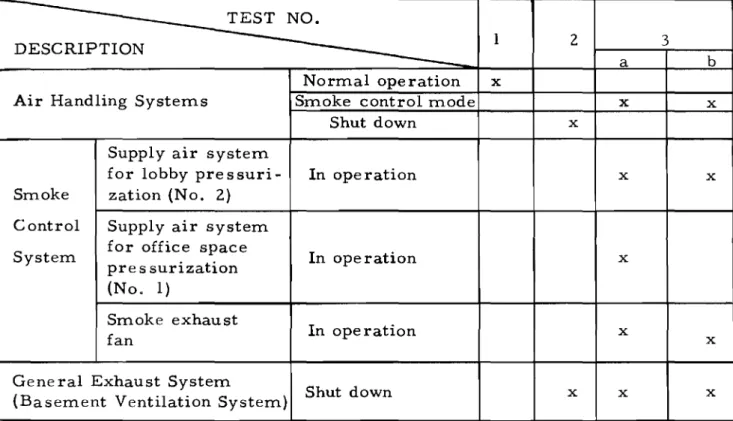
OF TESTS
A total of four tests were conducted. Tests nos. 1 and 2, were conducted to establish the air flow pattern of the building with the air conditioning systems both in operation and shut down. Te st nos. 3a and b were conducted to check the performance of the smoke control system. Pressure difference measurements across various exterior and interior
-3-doors were taken during all te st s . The rates of outside supply and ex-haust air were measured during Test no. 3. In addition rates of air exhaust at the discharge grilles for lobby pressurization were also
mea-sured on nine floors. Details of the test conditions as well as the results of pressure and air flow rate measurements for the four tests are shown in Table I and Figure s 4 to 8.
RESULTS AND DISCUSSIONS
The tests were conducted on a windy day with an average easterly wind speed of 25 mph. Outside air temperatures. taken at various
times during the tests. averaged 39°F. In general, the pressure difference across various interior doors was small relative to the fluctuation in the readings. The recorded readings are approximate value s ,
Test No.1: Air handling system in normal operation
With the air handling system in normal operation. Figure 4 shows that the pressures in the lobby spaces were less than those in the stairwell, elevator shaft, and office spaces. The low pressures in lobby spaces are probably caused by the operation of the washroom exhaust systems which extract air from the lobby space s , The pre s sure s in the office space s are generally higher than those of the elevator and stair shafts. Opening of the lobby doors on a floor, therefore, can cause a flow of air from the office space into these shafts and into the lobby spaces of other floors. Test No.2: Air handling systems shut down
With the air handling system shut down, Figure 5 indicates that the neutral pre ssure plane of the lobby space. with respect to the office space, is located at about the 10th floor. Below this, the pressures in the office
spaces are higher than those of the centre core while above the reverse is the case. The direction of air flow is, therefore, from the office spaces to lobbies and vertical shafts below the 10th floor and from the stair and elevator shafts to lobby and office spaces above the 10th floor.
Test No.3: Smoke control system in operation
Two tests were conducted with the smoke control system in operation. Test no. 3a was carried out with the two supply fans (office and lobby spaces) and the exhaust fan (office spaces) in operation. Figure 6 indicates that below the 5th floor the pressures in the lobby spaces are lower than those in the office spaces and are higher than those in the vertical shafts; above the 5th floor, the reverse is the case. Te st no. 3b was similar to 3a except that the supply fan system of the office spaces was shut down. Figure 7 indicates that the pressure differences across various interior doors are somewhat similar to those of Test no. 3a.
-4-An e xarn iriat i on of Figures 5, 6 and 7 indicates that the operation of the smoke control system did not significantly alter the flow pattern caused by building stack action. It also indicates that with the smoke control
system in operation only minimal pre s surization of the lobby space s on the lower levels and slight pre s surization on the upper levels were obtained. To further investigate the performance of the smoke control system, air supply rates to lobby spaces and air exhaust rates from office spaces were measured on nine floors. The results shown in Figure 8 indicate that the
vertical distributions of supply and exhaust air rates were not uniform. The rates on the higher floor levels were much greater than those on the lower floor levels. The rates of air supply to lobby spaces in terms of air change per hour varied from 27 for the 14th floor to 4 for the 2nd floor.
The test results indicate that the flow capacities of the supply air system is inadequate to achieve significant pressurization of the lobby spaces, particularly on the lower floors. The pressurization system could be made more effective by increasing the supply air rate sand
eliminating some of the source s of air leakage in the lobby enclosure such as those of the washroom exhaust systems. The smoke exhaust system could be made more effective by allowing it to exhaust from only the office space of the fire floor.
ACKNOWLEDGEMENT
The authors are grateful for the cooperation and assistance of Glen-view Realty (Ottawa) Ltd. and Belasky and Associates and wish to acknow-ledge the contribution made by J. H. McGuire and R. G. Evans in performing the field tests.
TABLE I TEST CONDITIONS
WIND E. 25 MPH, OUTSIDE AIR TEMPERATURE 39°F
DESCRIPTION
Air Handling Systems
TEST NO. Normal operation Smoke control mode Shut down 1 x 2 x a x 3 b x Smoke Control System
Supply air system for lobby
pressuri-zation (No. 2)
Supply air system for office space pre s surization (No. 1) Smoke exhaust fan In operation In ope ration In operation x x x x x
Gene ral Exhaust System
MセMMMMM
...
LMセNセMセ .. -Figure 1
-46" X 11" SMO KE SHAFT INTAKE
2
AIR DUCT, SPACE 5 HEAT r Iセ
GRILLE MAIN EXHAUSTSHAFT TO AIR SUPPLY
BASEMENT SHAFT FOR
LOBBY
SUPPLY AIR DUCTS
TO FLOOR AREA 49"
X 30"
FRESH AIR SUPPLY SHAFT RETURN
TERMINATE ABOVE MAIN CEILING SINGER MODEL FV520 -PUMP UNIT
NjLiZZ]セQM[W
LセL
x 17"JC::::::::j---Uf---j
PRESSURIZATIONセNNNNNNMMMMMM
EXHAUST SHAFT TO BASEMENT FIGURE 2TYPICAL FLOOR PLAN OF CENTRAL CORE
10 9 7 6 GROUND 1st BASEMENT 2nd BASEMENT
;
:=--I
FIGURE 3SMOKE CONTROL SYSTEM
BR 5163-2
LEGEND
Q)
OUTSIDE AIR SUPPLY SYSTEMS, 15,000 CFM EACHo
EXHAUST FAN, 35,000 CFMG)43 SMOKE EXHAUST SHAFT
@
SUPPLY AIR SHAFT NO. 1 FOR OFFICE SPACE PRESSURIZAT 10 N®
SUPPLY AIR SHAFT NO. 2, SEALED WITHDAMPER UNDER SMOKE CONTROL MODE
®
SUPPLY AIR SHAFT FOR LOBBY PRESSURIZATIONCD
DAMPER, CLOSED UNDER SMOKE CONTROL MODE®
DAMPER, OPEN UNDER SMOKE CONTROL MODE®
DAMPER, OPEN UNDER SMOKE CONTROL MODELOBBY SPACE 15M 14
Dec
1 2•
1 0 0::0
0
..J u,..
I -Io
UJ I 8 6 4-
AIR HANDLING SYSTEMS IN NORMAL OPERATIONQ[»
0
. 0
8
•
0 0 .
2 G8
0
•
2Bo
STAIRWELL • OFFICE SPACEo
ELEVATOR SHAFT•
0
.016 .008
o
.008 .016PRESSURE DIFFERENCES ACROSS LOBBY DOORS, INCH OF WATER
FIGURE 4
PRESSURE MEASUREMENTS FOR TEST NO.1
LO BBY S PAC E 15M 1 4
•
0
0
1 20
10
AIR HANDLING SYSTEMS SHUTDOWN 80
0<:0
8
--I u. 6 l-0
STAIRWELL•
OFFICE SPACE0
ELEVATOR SHAFT I•
o
8
u.J I 4010
•
2•
G00
•
2B .02 .016 .008 0 .008 .016 .02 PRESSURE DIFFERENCES ACROSS LOBBY DOORS,INCH OF WATER
FIGURE 5
PRESSURE MEASUREMENTS FOR TEST NO.2
15M LOBBY SPACF 14
•
00
•
DO
12•
00
1 0•
DO
0::: 0 0 J u... 8 6 SMOKE SYSTEM<»0
CONTROL IN NORMA L0
STAIRWELL•
OFFICE SPACE0
ELEVATOR SHAFT t - OPERATION J:e
8
.1
LU J: 4 2 G8
8
00
•
•
•
2B .02 .012 .008 0 .008 .016 .02PRESSURE DIFFERENCE ACROSS LOBBY DOORS, INCH OF WATER
FIGURE 6
PRESSURE MEASUREMENTS FOR TEST NO.
30
F
15M 14•
1 2 10 SMO KE CONTROL 8 IN OPERATION (OFFICE SPA C Eo
o
PRESSURIZATION -J FA N SHUTDOWN) u... 6 f--:r:o
u.J 4 :r: 2 G 2Bp
LO BBY SPA C E 0•
0
0•
0•
00
SYSTEM 0 STAIRWELL0
•
•
0 OFFICE SPA C E0
ELEVATOR SHAFT00 •
I
00
•
- .02 -.016 -.008o
.008 .016 .02PRESSURE DIFFERENCE ACROSS LOBBY DOORS I
INCH OF WATER
FIGURE 7
PRESSURE MEASUREMENTS FOR TEST NO. 3b BR 5163-6
1
14 ____-0-o
....-
-",... 1 2 / ' "..,./Q
,/' 1 0/
C<:a
o
/
0 I/
LL. 8/
/
..
セ :r:o
AIR EXHAUST RATE FROMUJ
6
•
:r:
/
OFFICE SPACE/ t
o
AIR SUPPLY RATE TOLOBBY SPACE 4
/
2•
o
200 400 600 800 1000 1200 1400 1600 1800 2000 FLO W RA TE I C FM FIGURE 8FLOW RATES OF OFFICE SPACE EXHAUST AND LOBBY PRESSURIZATION VS FLOOR LEVEL BR51637