HAL Id: hal-02110193
https://hal.archives-ouvertes.fr/hal-02110193
Submitted on 25 Apr 2019
HAL is a multi-disciplinary open access
archive for the deposit and dissemination of
sci-entific research documents, whether they are
pub-lished or not. The documents may come from
teaching and research institutions in France or
abroad, or from public or private research centers.
L’archive ouverte pluridisciplinaire HAL, est
destinée au dépôt et à la diffusion de documents
scientifiques de niveau recherche, publiés ou non,
émanant des établissements d’enseignement et de
recherche français ou étrangers, des laboratoires
publics ou privés.
Towards the implementation of natural prosthetic elbow
motion using upper limb joint coordination
Manelle Merad, Agnès Roby-Brami, Nathanael Jarrasse
To cite this version:
Manelle Merad, Agnès Roby-Brami, Nathanael Jarrasse. Towards the implementation of natural
prosthetic elbow motion using upper limb joint coordination. 2016 6th IEEE International Conference
on Biomedical Robotics and Biomechatronics (BioRob), Jun 2016, Singapore, Singapore. pp.821-826.
�hal-02110193�
Towards the implementation of natural prosthetic elbow motion using
upper limb joint coordination
Manelle Merad, Agn`es Roby-Brami and Nathana¨el Jarrass´e
Abstract— The control of an active prosthetic elbow is problematic for most transhumeral amputees and a functional solution providing intuitive control over active multi-joint prosthetic upper limbs is yet to be found. The method in this paper uses IMU-based upper arm kinematics to predict the elbow motion based on upper limb joint coordinations during pointing movements. A RBFN-based regression was performed to model the shoulder/elbow coordination. The prediction results indicate that such an approach is ready to be implemented on current transhumeral prostheses equipped with embedded motion sensors like IMUs. Different algorithm training methods to obtain better prediction performance are also investigated.
I. INTRODUCTION
For the past fifty years, the progress of mechatronics has permitted the development of more and more anthro-pomorphic prosthetic limbs, especially prosthetic hands [1]. However, few solutions have been developed for patients with transhumeral or higher amputation levels: there are passive prosthetic elbows, like the 12K44 ErgoArm HybridR Plus (Ottobock c ) that can be locked manually into a desired position, and a limited number of active prosthetic elbows, like the DynamicArm 12K100 (Ottobock c ), and the Uta-hArm3+ (Motion Control, Inc.). Most transhumeral amputees report that their prosthesis is lacking functionality, and that it does not provide the expected assistance in Activities of the Daily Living (ADLs) [2]. A counter-intuitive control strategy is often cited as a limiting factor of prosthesis usage.
The most common method to control an active pros-thetic upper limb is myoelectric control. Contractions of two antagonistic residual muscles (biceps and triceps brachii for transhumeral amputees), measured with surface elec-tromyographic (sEMG) electrodes, are directly controlling a prosthetic function, such as hand opening/closing, or wirst pronosupination. A co-contraction (i.e. simultaneous con-tractions of antgonistic muscles), or combination of muscle contractions, is then required to switch from one mode (e.g. hand closing/opening) to another (e.g. internal/external wrist rotation). Myoelectric control is limited by the influence of EMG signals to electrodes placement, skin impedance, muscle fatigue, and signal filtering, and thus, has been for a long time used as an on/off control stategy, even if more
This work was performed within the Labex SMART (ANR-11-LABX-65) supported by French state funds managed by the ANR within the Investissements d´ Avenir programme under reference ANR-11-IDEX-0004-02.
The authors are with CNRS, UMR 7222, ISIR, F-75005 Paris, France, also with INSERM, U1150, Agathe-ISIR, F-75005 Paris, France, and also with Sorbonne Universit´es, UPMC Univ Paris 06, UMR 7222, ISIR, F-75005 Paris, France,[email protected]
advanced methods have been developed in the last decades [3]. Although the number of degrees of freedom (DoFs) to control increases with the amputation level, the same on/off control strategy is applied to forearm and arm prostheses, yielding a dimensionality issue with more controllable out-puts than control inout-puts. Transhumeral amputees eventually achieve good control of hand and wrist, but have difficulties in general when an active myoelectrically-controlled elbow is added to the prosthetic arm. Arm amputation level has a strong influence on the affected person’s ability to perform ADLs, and compared to lower amputation levels, the com-pensatory strategies developed by transhumeral amputees to overcome the impairment involve significantly more the rest of the body, causing shoulder, back, and contralateral limb disorders [4]. Numerous studies have investigated alterna-tives to bi-electrodes myoelectric control, such as solutions based on ultrasound signal [5], myokinemetric signal [6], myokinetic signal [7], mechanomyographic signal [8], and residual limb motion [9], [10]. One possible and yet less explored solution relies on the use of residual limb motion and the knowledge of human upper limb motor control to design a more natural control strategy.
The human upper limb is characterized by its number of degrees of freedoms (DoFs) (9, including the scapula elevation and protraction), greater than the required number to position and orientate the hand in a 3D space. Upper limb prosthetics are built with numerous DoFs in order to duplicate the human arm mobility. A big issue of replicating the human upper limb behavior is to find the most natural kinematic solution for the given number of DoFs despite the redundancy of human arm motion. Instead of consid-ering motor control as a single input (neural signal-single output) (one muscle) control scheme, human arm motion is explained in several studies by a coordination between joint kinematics that depend on the performed task [11], [12]. Previous analyses of upper limb movements during reaching or grasping tasks have shown evidence of recurrent patterns in joint kinematics, for instance between wrist and fingers [13], as well as between movement direction and hand azimuth [14], and humeral inclination and elbow flexion [15]. This coordinated joint motion yields intuitive upper limb motion during which one focuses only on hand action.
Intuitiveness is a sought characteristic for upper limb prosthetic control, and the joint coordination approach is a promising solution in which a prosthetic joint is controlled automatically based on natural relationships between joints. Researchers have been trying to model the coordination between upper limb joints, and several regression tools have
been used in the literature to model the mathematical rela-tionship between proximal and distal joints motion. Principal Component Analysis (PCA) is a common approach, although linear, to model inter-joint relationship: it is applied in [16] to lower limb prostheses to predict distal joint motion. Although prosthetic lower limbs are active as well, their control scheme uses the repeatability of the human walking pattern, and thus, it is easier to predict the knee motion based on the analysis of the healthy contralateral lower limb joints. Prediction of upper limb distal joints is complicated by the fact that the system does not know what activity the user wants to perform with the prosthesis. A solution is to model the human upper limb control strategy for different tasks (e.g. reaching). The study in [17] used Inertial Measurement Units (IMUs) to measure the upper limb joints angles; a correlation was found between humeral inclination and wrist rotation, but the inter-joint relationship was not modeled. Since the function that relates upper limb kinematics is likely to be nonlinear, Artificial Neural Networks (ANNs) are best suited to approximate the relationship between shoulder and elbow kinematics. The ANN architecture is tested in [18] where data are acquired for a pointing task in a 3D workspace. The selected inputs/outputs combination for the ANN would require the measurement of 3 shoulder angles (humeral inclination, humeral longitudinal axis direction, humeral ro-tation), and 2 shoulder translations (protraction/retraction, and elevation/depression), which is difficult to achieve in non-laboratory environments. Also, movements towards the numerous targets were performed only once, which suggests that human variability was not taken into account. Upper limb joints coordination for various ADLs are modeled in [19] using Radial Basis Function Networks (RBFNs), but the manipulated objects’ positions remained in a 2D workspace and the established model requires that the direction in which the prosthesis user wants to point is known prior the initiation of movements. Popovi´c et al. in [20] fed a similar ANN architecture with goniometer-based upper limbs measurements to investigate the coupling between shoulder and elbow angular velocities. Nevertheless, none of these methods has been tested in a real case scenario, when camera-based motion capture systems are not available.
The approach presented in this paper uses upper limb coor-dinations from two different individuals to predict accurately the elbow flexion kinematics during pointing movements in a 3D workspace. In order to fullfil the embodiment requirements of prosthetic devices, one IMU is utilized to measure the humeral orientation, represented by the humerus inclination and direction angles, inputs of the RBFN-based regression algorithm that is performed on recorded data to model the relationship between shoulder and elbow angular velocities. The experimental setup, data recording and analy-sis methods are described in Section II. The results, presented in Section III and discussed in Section IV, demonstrate the ability of the proposed system to predict the elbow angular velocity using IMU-based upper arm kinematics.
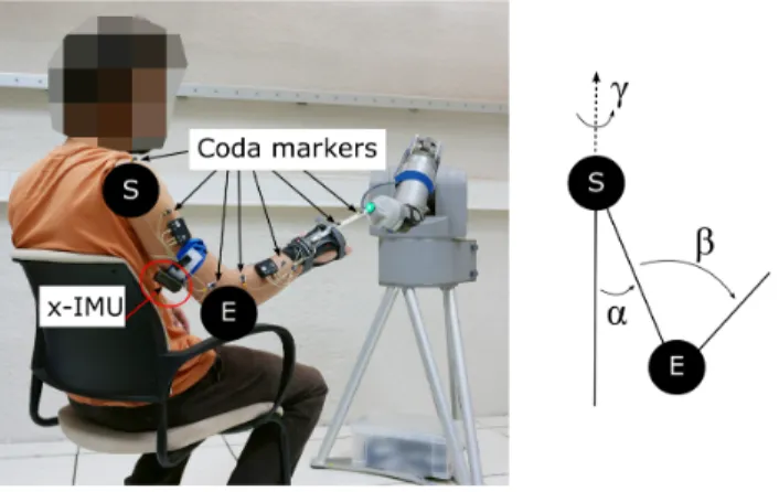
Fig. 1. Experimental setup. The subject is pointing at a target with a rod rigidly attached to a wrist splint. The target is presented to the subject by a WAM robotic arm. The subject is equipped with motion capture sensors and an x-IMU attached to his arm. The arm and forearm orientation is represented by the anatomical angles γ, α, and β.
II. MATERIALS ANDMETHODS
A. Subjects and experimental setup
Two healthy right-handed individuals, female and male, (age 24 and 31, respectively 1,72 m and 1.90 m) participated in the study. The experiment consisted in recording upper limb pointing movements, and lasted about one hour for each participant. Participants pointed at targets with their right hand while sitting comfortably on a chair, as illustrated in Fig. 1. The subjects wore a wrist splint, designed for sport activities, to prevent wrist flexion, and used a rod rigidly attached to the splint’s back, instead of their index, to reach the targets. The targets, a bright push button mounted on a 7-DoF robotic arm (WAMTMarm, Barrett Technology, Inc.), were randomly presented to the subjects, as shown in Fig. 1; subjects could not predict target locations since they were shown only one at a time.
B. Experimental protocol
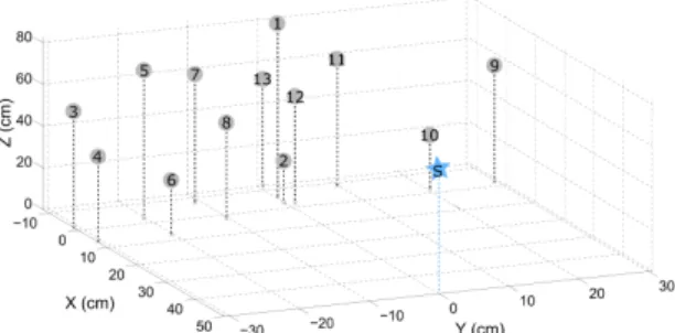
The task consisted in pointing at 13 targets located in front of the subjects, as illustrated in Fig. 2. Targets were located within a workspace of size 20x60x60 cm3, and were the same in the WAM arm reference frame for the two participants; subject-robot distance was adjusted prior the session such that subjects reached all targets with maximal arm extension only. The subjects were asked not to move their trunk during the experiment. The starting position, to which they had to come back after each movement, was defined after all sensors were placed on the subjects: the participants were sitting on a chair, with their forearm resting on the armrest. No particular instruction on movement duration or speed was given to the participants. For each target, the subject stayed for 2 seconds at the starting position, went towards the target, pushed the button with the rod tip, stayed immobile for 2 seconds, went back to the starting position while the robot arm was moving its end-effector towards the next target position. Each trial of 13 targets was performed three times with both subjects.
Fig. 2. Positions of the 13 targets to which each subject pointed at during each trial. The star-shaped marker denotes the shoulder location.
C. Apparatus
Upper limb movements were recorded using two types of motion sensors. The first is a camera-based motion capture system, Codamotion (Charnwood Dynamics Ltd.), that uses infrared cameras to locate infrared emitting markers placed on the subjects; 2 cameras were used in the setup and 7 markers were placed on the subject’s right arm, as depicted in Fig 1. In parallel, an x-IMU (x-io Technologies, Ltd.) was placed on the subject’s arm, as shown in Fig. 1, and measured upper arm orientation represented as quaternions using the embedded sensor fusion algorithm AHRS (Attitude Heading Reference System) [21]. The x-IMU was reset after marker placement. The acquisition frequency was respectively 100 Hz for the Codamotion system, and 128 Hz for the x-IMU. D. Data processing
Data from the two measurement systems were synchro-nized offline. In order to describe the arm posture, the shoulder and elbow angles, introduced in [22] and illustrated in Fig. 1, were utilized with the following notation: γ, the direction angle, characterized the humerus pointing direction, α, the inclination angle, represented the angle between the humeral longitudinal axis and the trunk vertical axis, and β described the elbow flexion angle. For instance, the angular configuration (γ,α,β) was (0,90,180) deg in right lateral shoulder abduction with maximal arm extension, whereas the starting position corresponded to the angular configuration (0,0,90) deg.
Shoulder angles were derived from both Codamotion and x-IMU data, while the elbow angular position was derived from the Codamotion system. Shoulder and elbow angular velocities were numerically computed from angular position measurements. Data were partitioned for each movement (13 targets, 3 trails, 2 subjects, i.e. 78 movements) and low-pass filtered.
E. RBFN-based regression: training and testing
RBFN-based regression, described in [23] and imple-mented in a Matlab script, is performed to model the relationship between ( ˙γ, ˙α) and ˙β. This method comprises two steps: 1) a training phase that uses a training data set (measured triplets ( ˙γ, ˙α, ˙β) to approximate the nonlinear function that relates shoulder kinematics to elbow angular velocity, 2) a testing phase that uses the approximated
function to estimate the elbow angular velocity based on measured shoulder kinematics ( ˙γ, ˙α) from a testing data set. Four tests were performed to assess the performance of the modeled function with kinematic information from a selected trial (13 movements); they are described as following:
• Test A (intra-individual training, intra-individual test-ing): the training data set comprises data of 2 out of 3 trials from Subject 1 (resp. Subject 2), i.e. 2 x 13 movements. The test is performed on Subject 1’s (resp. Subject 2’s) remaining trial (i.e. 1 x 13 movements), and is designated as test A-S1 (resp. A-S2). Results for each subjects are then averaged (A-av).
• Test B (intra-individual training, inter-individual test-ing): the algorithm is trained with data from Subject 1’s (resp. Subject 2’s) trials (i.e. 3 x 13 movements), and is tested on Subject 2’s (resp. Subject 1’s) trials. Test results are designated as B-S1 (resp. B-S2), and are then averaged between both subjects (B-av). • Test C (inter-individual training, inter-individual
test-ing): data from both subjects are mixed in the training data set, which comprises 5 out of the 6 trials. The approximation function is tested on the remaining trial; results are then averaged for all tested trials.
• Test D (spatial generalization): like in test C, the regres-sion model is obtained from both subjects’ data, except that some targets are not included in the training data set: targets number 5, 6, 7, 8, 10, and 11 are removed. However, the model is tested on the 13 movements of the remaining trial.
F. Analysis
For each test, predicted elbow angular velocity results are compared to Codamotion-based elbow flexion angu-lar velocity. Several metrics are computed to evaluate the performance of RBFN-based regression, such as the Root Mean Square (RMS) error between measured and estimated elbow angular velocity RM Svel, the relative error between the maximum values of measured and estimated angular velocities Errpeak, the RMS error between measured elbow angle and reconstructed elbow angle from integration of estimated angular velocity RM Spos, and the relative error between the measured and estimated final angular positions Errf inal.
III. RESULTS
A. IMU measurements
A comparison between Codamotion- and x-IMU-based shoulder joint configuration reconstruction is performed after recording the data, in order to quantify the IMU’s recon-struction error. The angular position RMS error between Codamotion and x-IMU-based reconstruction is 21.99 deg (SD 14.37 deg) for the direction angle, and 2.10 deg (SD 2.22 deg) for the inclination angle. The angular difference between Codamotion and x-IMU is explained by a constant drift on the direction angle. Nevertheless, since the upper limb movement model is developed in the angular velocity space, the drift has little influence: the angular velocity RMS
Fig. 3. Example of elbow angular velocity during one out of 13 pointing movements to represent the intra-individual and inter-individual variability. The solid lines represent the measured elbow angular velocities for Subject 1 (in blue) and 2 (green) averaged over 3 trials. The shaded areas represent the standard deviation around the mean value.
Test type RM SAngular velocity errors Angular position error
vel(deg/s) Errpeak(%) RM Spos(deg) Errf inal(%)
A-S1 7.08 29.51 7.18 36.04 A-S2 9.76 20.02 6.94 17.67 A-av 8.42 24.77 7.06 26.85 B-S1 9.61 59.80 10.8 62.06 B-S2 20.6 44.14 19.5 45.77 B-av 15.1 51.97 15.2 53.92 C 7.85 27.61 6.89 28.42 D 7.62 27.84 6.70 28.53 TABLE I
RESULTS OF COMPARISON BETWEEN ESTIMATED AND MEASURED ELBOW ANGULAR VELOCITY FOR TESTSA, B, C,ANDD
error is 2.89 deg/s (SD 5.23 deg/s) for the direction angle, and 1.67 deg/s (SD 2.95 deg/s) for the inclination angle. B. Subjects variability
Measured elbow angular velocities were averaged for each subject, and the corresponding standard deviations were computed, as illustrated in Fig. 3, to assess the human movement repeatability. The overall variation around the elbow angular velocity mean values is 3.61 deg/s (SD 0.002 deg/s), averaged over all trials and all subjects. Peak value of the angular velocity profile, as well as movement duration, are important features that determines the elbow movement amplitude. Thus, the standard deviation of elbow angular velocities averaged over all trials is computed at the time when the peak occurred: an overall variation of 11,82 deg/s for Subject 1, and 30.58 deg/s for Subject 2, was observed around the mean peak value (averaged over all targets). C. RBFN-based regression
Results from the intra- and inter-individual tests are grouped in Table I. For intra-individual training and testing (test A), the overall elbow angular velocity RMS error is 8.42 deg/s (SD 3.85 deg/s), averaged over the two participants. The overall final position error, after integration of estimated angular velocity, is 26.85 % (SD 33.01 %) of measured final elbow position.
For intra-individual training and inter-individual testing, training and testing data are taken from data sets of different
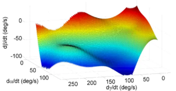
Fig. 4. Three-dimensional representation of the RBFN-based function ap-proximation between shoulder and elbow kinematics. The surface represents the elbow angular velocity ˙β with respect to humeral pointing direction ˙γ and humeral inclination ˙α.
subjects (test B). Testing on Subject 2’s data while using a Subject 1’s data-based model yields an angular velocity peak error of 59.80 % (SD 52.92 %) of measured peak angular velocity. The final position error reaches 53.92 % (SD 49.57 %), averaged over the two subjects.
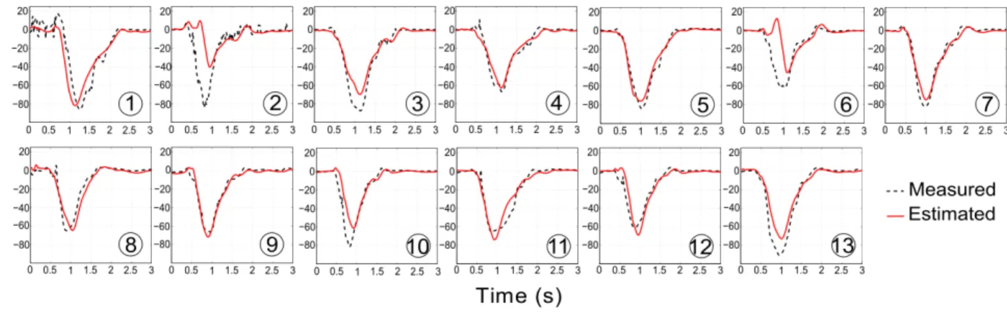
When training includes trials from both subjects (inter-individual training and testing, test C), the overall angular velocity error is 7.85 deg/s (SD 4.00 deg/s), and the position RMS error is 6.89 deg (SD 4.63). The overall coefficient of determination between measured and estimated elbow angu-lar velocity is 0.78. An example of approximation function for test C, obtained by training the algorithm with data sets from Subjects 1 and 2, is illustrated in Fig. 4; Matlab surf method was utilized to represent the model. Fig. 5 depicts estimated elbow angular velocities using test C-based model: training is performed on 5 trials (3 from Subject 1’s, 2 from Subject’s data sets), and model, represented in Fig. 4 is tested on the 13 target movements of Subject 2’s remaining trial.
Finally, results of generalization tests (test D: inter-individual training and testing, with a reduced number of training targets) are similar to test C’s results: the overall angular velocity RMS error is 7.62 deg/s (SD 3.60 deg/s), and the final position error is 28.53 % (SD 42.01 %) of measured final elbow angular position.
IV. DISCUSSION
A. IMU-based arm motion capture
An x-IMU was placed on two subjects’ upper arm, and its embedded AHRS algorithm reconstructed the humeral orientation, represented as quaternions, based on a fusion of accelerometer’s, gyroscope’s and magnetometer’s data. Afterwards, the humeral orientation was expressed in terms of anatomical angles, direction and inclination angles. A Codamotion system was also employed to measure both the arm’s and forearm’s orientation, and a comparison was performed between IMU- and Codamotion-based angular reconstruction. A low error between the two systems in terms of angular velocity justifies the use of an IMU with embedded orientation algorithm as a shoulder kinematics measurement system. The error was higher for the direction angle because of a constant drift.
Using a prosthesis equipped with an IMU as motion measurement sensor requires that the system is robust to
Fig. 5. Elbow angular velocity estimation results for a test on Subject 2’s 3rd trial. Training data from both subjects were used to model relationship between shoulder and elbow (inter-individual training and testing). Dashed lines represent Codamotion-based elbow angular velocity, and solid lines represent RBFN-based elbow angular velocity.
internal drift and external perturbation, such as user body motion (e.g. walking, trunk motion) and external environ-ment disturbance. Drift-free IMU-based measureenviron-ment is still to be achieved for long-term usage, although embedded algorithms of commercialized sensors are well advanced to provide satisfying measures. The need for a magnetometer in the measurement system is demonstrated in [24] where accelerometer and gyroscope fusion-based measures were drifting. A suggested solution is to combine multiple IMUs to cancel effects of external perturbations.
B. Upper-limb coordination-based elbow motion estimation A RBFN-based regression algorithm was implemented to model the relationship between shoulder and elbow angular velocities during a pointing task, and test results from different training data sets were compared. Intra-individual training and testing was expected to be the most natural test (test A): the aim was to learn the coordination pattern of one subject, and to test the modeled relationship on the same subject’s data. The results show that the final position error between measured elbow angular position and the integration of estimated angular velocity (i.e. reconstructed position) remains below 10 degrees for tests on both subjects. This suggests that the presented method is capable of predicting the elbow motion of one person with an accuracy of 10 degrees during a 3D pointing task when establishing a model based on this same person’s data; only IMU-based measurements of humeral inclination and direction were utilized as regression algorithm inputs. Kaliki et al. in [18] obtained similar results although they used a camera-based motion capture system, and more ANN input signals (3 shoulder angles, and 2 shoulder translations) to determine the elbow angle in a 3D pointing task.
Elbow kinematic information cannot be measured with transhumeral amputees; hence, algorithm estimation results must be robust to inter-individual testing, and capable of pre-dicting elbow angular velocity based on amputees’ residual arm motion measures using a model that was obtained with healthy individuals. This property is tested with test B by
training the algorithm on one subject’s data, and by testing the model on the other subject’s data. High estimation errors were found: the overall final position error is above 50 % of the measured elbow angular position. Results show the algorithm’s inefficiency when compared with data from a coordination pattern that are not included in the training data set. This suggests that the participants’ pointing movement strategies are very different, and that each individual’s natural coordination pattern may not be generalized, at least not with the tested coordinations and mapping (elbow flexion in relation with humeral incination and humeral direction). Iftime et al. in [19] obtained mixed results for inter-individual testing: the correlation coefficient value was 0.94 for estima-tion of elbow angular acceleraestima-tion for a 2D reaching task based on shoulder flexion angular acceleration, and -0.96 based on shoulder abduction angular acceleration. However, they trained the RBFN-based ANN on goniometer-based data from only one target location and tested the model on the same target location.
An explanation for unsatisfying test B results is that the algorithm training did not account for the inter-individual variability: the algorithm predicted angular velocity val-ues based on the learned coordination from one subject. Therefore, a solution to improve the estimation results is to include inter-subject variability in the training data set. Test C mixes data from both participants to model the shoulder/elbow coordination for pointing movements, and results are comparable to intra-individual test results: the overall angular velocity error is 7.85 deg/s, and the final elbow position error is below 30 % of measured elbow angle, which is slightly above the final position error for intra-individual training and testing (26.85 %). Even though the preceding test indicate that the algorithm is unable to predict the elbow motion pattern if it was not in the training data set, the last results suggest that it is capable of distinguish between the different coordinations included in the training. Better results could also be expected if more coordination patterns are included in the training data set.
targets that were included in the training data set, from the same subject or not: the workspace explored during testing is discretized and the results do not allow to conclude on the system response in a real prosthesis application, where workspace is continuous. The prosthesis user must be able to bring the prosthetic hand to a location that was not included in the training data set, i.e. in between target locations that were included. Test D justifies the algorithm’s ability to predict elbow motion for movements towards targets which it was not trained on. Results are close to inter-individual training and testing results (test C): even though the angular velocity RMS error is less than the one of test C, final elbow position error, below 30 % of measured elbow angle, is slightly above test C’s final error. These results, almost as good as intra-individual training and testing tests, suggest that the algorithm is possibly overtrained, i.e. that it does not need that much training information to predict accurately the elbow angular velocity. There were between 400 and 500 target locations distributed in the workspace in front of subjects in the study in [18] that also tested ANN gener-alization property; in comparison, the regression algorithm in our study was trained on only 7 pointing movements from both subjects. By using an angular velocity-based model, initial position is unconstrained and movements from different starting positions could be performed; in addition, IMU-based drift effects are canceled.
C. Towards implementation on prostheses
Data sets from two different individuals were successfully put together to estimate the elbow motion for a pointing task at 13 targets. Results of this study highlight the importance of algorithm training data set: including data from more than one subject yields good performances, and reducing the data training set to a smaller number of targets could improve the performance thanks to the model’s generalization property between target locations.
Future work will be focused on the effect of the chosen input signal set on the algorithm’s performance. In this study, humeral direction and inclination were chosen to estimate the elbow flexion angular velocity, but different and more input signal combinations could have been used. The pointing task is too restrictive in ADLs, and therefore, an important extension of this work is to verify the performance of such an architecture to model coordination patterns in different ADLs that are more common in daily prosthetic usage. Moreover, difference between amputees and healthy indi-viduals humeral movements should be taken into account: important differences in the coordination patterns and in the arm segment motion should be expected because of motor compensation strategies. Since real time accurate orientation estimation is possible with current IMUs, usage of inertial sensors in prosthetics will increase in a close future.
REFERENCES
[1] J. T. Belter, J. L. Segil, A. M. Dollar, and R. F. Weir, “Mechanical design and performance specifications of anthropomorphic prosthetic hands: a review,” J. Rehabil. Res. Dev., vol. 50, no. 5, pp. 599–618, 2013.
[2] E. Biddiss and T. Chau, “Upper-limb prosthetics: critical factors in device abandonment,” Am. J. Phys. Med. Rehabil., vol. 86, no. 12, pp. 977–987, 2007.
[3] E. Scheme and K. Englehart, “Electromyogram pattern recognition for control of powered upper-limb prostheses: State of the art and challenges for clinical use,” J. Rehabil. Res. Dev., vol. 48, no. 6, p. 643, 2011.
[4] K. Østlie, R. J. Franklin, O. H. Skjeldal, A. Skrondal, and P. Magnus, “Musculoskeletal pain and overuse syndromes in adult acquired major upper-limb amputees,” Arch. Phys. Med. Rehabil., vol. 92, no. 12, pp. 1967–1973, 2011.
[5] D. S. Gonz´alez and C. Castellini, “A realistic implementation of ultrasound imaging as a human-machine interface for upper-limb amputees,” Front. Neurorobot., vol. 7, 2013.
[6] R. L. Abboudi, C. Glass, N. Newby, J. Flint, W. Craelius, et al., “A biomimetic controller for a multifinger prosthesis,” IEEE Trans. Rehabil. Eng., vol. 7, no. 2, pp. 121–129, 1999.
[7] M. Kuttuva, G. Burdea, J. Flint, and W. Craelius, “Manipulation practice for upper-limb amputees using virtual reality,” Presence (Camb), vol. 14, no. 2, pp. 175–182, 2005.
[8] J. Silva, W. Heim, and T. Chau, “A self-contained, mechanomyography-driven externally powered prosthesis,” Arch. Phys. Med. Rehabil., vol. 86, no. 10, pp. 2066–2070, 2005. [9] Y. Losier, K. Englehart, and B. Hudgins, “Evaluation of shoulder
complex motion-based input strategies for endpoint prosthetic-limb control using dual-task paradigm,” J. Rehabil. Res Dev., vol. 48, no. 6, p. 669, 2011.
[10] R. D. Lipschutz, B. Lock, J. Sensinger, A. E. Schultz, and T. A. Kuiken, “Use of a two-axis joystick for control of externally powered, shoulder disarticulation prostheses,” J. Rehabil. Res. Dev., vol. 48, no. 6, p. 661, 2011.
[11] J. Soechting and F. Lacquaniti, “Invariant characteristics of a pointing movement in man,” J. Neurosci., vol. 1, no. 7, pp. 710–720, 1981. [12] M. Desmurget and C. Prablanc, “Postural control of three-dimensional
prehension movements,” J. Neurophysiol., vol. 77, no. 1, pp. 452–464, 1997.
[13] Y. Paulignan, C. MacKenzie, R. Marteniuk, and M. Jeannerod, “The coupling of arm and finger movements during prehension,” Exp. Brain Res., vol. 79, no. 2, pp. 431–435, 1990.
[14] A. Roby-Brami, N. Bennis, M. Mokhtari, and P. Baraduc, “Hand orientation for grasping depends on the direction of the reaching movement,” Brain Res., vol. 869, no. 1, pp. 121–129, 2000. [15] F. Lacquaniti and J. F. Soechting, “Coordination of arm and wrist
motion during a reaching task,” J. Neurosci., vol. 2, no. 4, pp. 399– 408, 1982.
[16] H. Vallery and M. Buss, “Complementary limb motion estimation based on interjoint coordination using principal components analysis,” in Computer Aided Control System Design, pp. 933–938, 2006. [17] F. Montagnani, M. Controzzi, and C. Cipriani, “Exploiting arm posture
synergies in activities of daily living to control the wrist rotation in upper limb prostheses: A feasibility study,” in EMBC, pp. 2462–2465, 2015.
[18] R. R. Kaliki, R. Davoodi, and G. E. Loeb, “Evaluation of a noninvasive command scheme for upper-limb prostheses in a virtual reality reach and grasp task,” IEEE Trans. Biomed. Eng., vol. 60, no. 3, pp. 792– 802, 2013.
[19] S. D. Iftime, L. L. Egsgaard, and M. B. Popovi´c, “Automatic determi-nation of synergies by radial basis function artificial neural networks for the control of a neural prosthesis,” IEEE Trans. Neural Syst. Rehabil. Eng., vol. 13, no. 4, pp. 482–489, 2005.
[20] M. Popovi´c and D. Popovi´c, “Cloning biological synergies improves control of elbow neuroprostheses,” IEEE Eng. Med. Biol. Mag., vol. 20, no. 1, pp. 74–81, 2001.
[21] S. O. Madgwick, “An efficient orientation filter for inertial and inertial/magnetic sensor arrays,” Report x-io and University of Bristol (UK), 2010.
[22] J. F. Soechting, C. A. Buneo, U. Herrmann, and M. Flanders, “Moving effortlessly in three dimensions: does donders’ law apply to arm movement?,” J. Neurosci., vol. 15, no. 9, pp. 6271–6280, 1995. [23] F. Stulp and O. Sigaud, “Many regression algorithms, one unified
model: a review,” Neural Networks, vol. 69, pp. 60–79, 2015. [24] P. Ertzgaard, F. ¨Ohberg, B. Gerdle, and H. Grip, “A new way of
assessing arm function in activity using kinematic exposure variation analysis and portable inertial sensors–a validity study,” Manual Ther., 2016.
![Two new 1-D dicyanamide bridged polymeric complexes [Mn(μ1,5-dca)2(salicyh)2]n and {[Ni(μ1,5-dca)(TTA)](ClO4)}n (dca = dicyanamide, ; salicyh = salicylic hydrazide; TTA = triethylenetetramine): Synthesis, structures and magnetic studies](data:image/gif;base64,R0lGODlhAQABAIAAAP///wAAACH5BAEAAAAALAAAAAABAAEAAAICRAEAOw==)