Adsorption at the Nanoparticle Interface for Increased
Thermal Capacity in Solar Thermal Systems
by Matthew W. Thoms B.S., Mechanical Engineering (2010) Tufts University MASCIUSETTS INSTi E OF TECHNOLOGY
-
--.--ARCHIVES
Submitted to the Department of Mechanical Engineering inPartial Fulfillment of the Requirements for the Degree of Master of Science in Mechanical Engineering
at the
Massachusetts Institute of Technology June 2012
©2012 Massachusetts Institute of Technology
All rights reserved
Signature of Author: ...
Department of Mechanical Engineering
May 23, 2012
C ertified by : ... -.- .-
-.---Evelyn N. Wang Associat ofessor of Mechanical Engineering
d- ")X TjpeirSupervisor
A ccepted by : ...-... :. . - - -
-David E. Hardt
Adsorption at the Nanoparticle Interface for Increased
Thermal Capacity in Solar Thermal Systems
by
Matthew W. Thoms
Submitted to the Department of Mechanical Engineering on May 2 3rd, 2012, in Partial Fulfillment of the Requirements for the Degree of Master of Science
Abstract
In concentrated solar power (CSP) systems, high temperature heat transfer fluids (HTFs) are responsible for collecting energy from the sun at the solar receiver and transporting it to the turbine where steam is produced and electricity is generated. Unfortunately, many high temperature HTFs have poor thermal properties that inhibit this process, including specific heat capacities which are half that of water. In an effort to enhance the effective heat capacity of these high temperature HTFs and thus increase the efficiency of the CSP systems, adsorption energy at the liquid-solid interface was investigated as a mechanism for increased thermal capacity.
Solid ceramic nanoparticles were dispersed in several molten salts at 1-2% by mass with diameters ranging from 5 nm to 15 nm to provide a significant available surface area for adsorption at the particle-molten salt interface. After successful nanofluid synthesis, differential scanning calorimetry (DSC) was used to measure anomalous deviations from the expected heat capacity and enthalpy of fusion values in the nanofluids. The variation in the sensible and latent heat values was determined to be dependent on the presence of sub-100 nm particles and attributed to a layer of salt that remains adsorbed to the surface of the nanoparticles after the bulk of the salt has melted. The adsorbed salt layer is expected to desorb at a higher temperature, providing an increased effective thermal capacity in the vicinity of this desorption temperature.
A thermal analysis technique utilizing DSC was proposed to approximate the thickness of the
adsorbed layer at the liquid-solid interface, a value that has previously only been obtained using simulation or transmission electron microscopy. More specifically, the adsorbed layer of LiNO3 on A1203 particles was determined to be 5.3-7.1 nm thick, similar to the 1-3 nm layers that have been observed in literature for simple, monatomic fluids. The results provide new insight into the nature of adsorption at the liquid-solid interface in more complex fluid and particle systems that can be harnessed for enhanced thermal capacity in HTFs.
Thesis Supervisor: Evelyn N. Wang
Acknowledgements
First, I would like to thank my advisor, Professor Evelyn Wang, for her mentorship and support throughout this project. Her trust and confidence in her advisees creates an environment that is challenging and rewarding for her students. I am very fortunate to have been able to benefit from her guidance over the past two years.
I would also like to acknowledge my sources of funding, the MIT Energy Initiative Enel
Fellowship and the Center for Clean Water and Clean Energy at MIT and KFUPM. Without their generous support, this work would not have been possible.
I must express my gratitude to my colleagues in the Device Research Laboratory for their
insight and intellect. I could never have imagined learning so much from my labmates and forming such great friendships in just two years. In particular, I would like to thank Andrej Lenert, Thomas Humplik, Dr. Ryan Enright, Dr. Youngsuk Nam, and Dr. Rishi Raj for all of the helpful discussions concerning this project and support during times of frustration.
I would like to thank my good friend, Madeline Green, for her encouragement and
perspective throughout my time at MIT. The joy that she brings to my life has had an enormous influence on my positive attitude and good spirits during difficult (and not-so-difficult) times. Finally, I would like to thank my parents for their infinite support. Although I know they would like me to be closer to home, they have always trusted me to pursue the opportunities I have earned, wherever they may take me.
Contents
1. Introduction... 13
1.1 M otivation... 13
1.2 Background... 16
1.3 Thesis Objectives And Outline ... 26
2. Predicting Enhanced Heat Capacity of Nanoparticle Mixtures ... 28
2.1 Increasing Therm al Capacity with Adsorption Energy ... 28
2.2 M odeling Heat Capacity Enhancem ent ... 31
2.3 Sum m ary ... 35
3. Experim ental M ethodology... 37
3.1 Sam ple Selection ... 37
3.2 D ifferential Scanning Calorim etry ... 38
3.3 X-Ray Diffraction ... 42
3.4 Therm ogravim etric Analysis ... 43
3.5 Sum m ary ... 43
4. Experim ental Results... 45
4.1 Li2CO3-K2CO2 N anofluid Results ... 45
4.2 H itec HTS N anofluid Results ... 49
4.3 LiNO 3 N anofluid Results... 54
4.4 Sum m ary ... 66
5. D ata Discussion and A nalysis... 67
5.1 Experim ental Results and the Traditional M ixing Rule ... 67
5.2 Q uantifying Adsorbate M ass ... 69
5.3 Approxim ating Adsorbed Layer Thickness... 71
5.4 Sum m ary... 74
6. Conclusions and Future W ork... 75
6.1 Contributions ... 75
6.2 Recom m endations for Future W ork ... 77
7. A ppendix ... 80
7.1 N anofluid Preparation Procedure ... 80
7.2 Mettler Toldeo Differential Scanning Calorimeter Standard Operating Procedure ... 82
7.3 M atlab Code for M odified M ixing Rule M odel ... 84
List of Figures
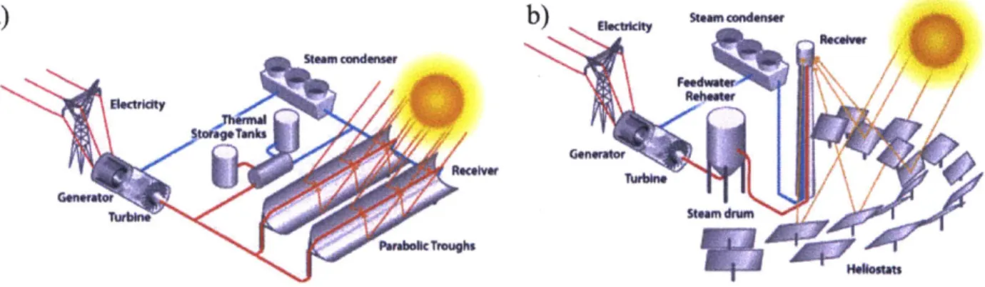
Figure 1. (a) Parabolic trough design and (b) power tower design for CSP plant...14
Figure 2. A simple diagram of a CSP cycle. A high temperature HTF is used on the receiver side (dashed) while water is used as the working fluid for the Rankine cycle (solid). ... 15
Figure 3. (a) SEM and (b) TEM images of polystyrene encapsulated paraffin particles. ... 18
Figure 4. Proposed mechanisms for increased specific heat of eutectic salt nanofluids . ... 21
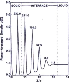
Figure 5. Density at a liquid-solid interface as predicted with density-functional theory ... 22
Figure 6. TEM image of solid alumina and liquid aluminum interface depicting an ordered liquid layer . ... 23
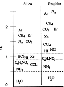
Figure 7. Expected relative change in melting temperature of interfacial layer for various adsorbates with silica or graphite substrate obtained by molecular dynamics simulations ... 25
Figure 8. Schematic representation of predicted thermal behavior of adsorbed layer in nanofluid based on behavior reported in high tem perature carbonate eutectic studies. ... 29
Figure 9. Schematic representation of predicted thermal behavior of adsorbed layer in nanofluid based on behavior reported in nanoporous substrate studies...31
Figure 10. Predicted changes in heat capacity of LiNO3 with 1% A1203 nanoparticles based on a modified mixing ru le in E q u atio n 5 ... 34
Figure 11. Simplified schematic illustrating the key components within a differential scanning calorimeter furnace. ... 3 9 Figure 12. Common temperature profile used in DSC when measuring specific heat capacity and enthalpy of fusion. ... 4 0 Figure 13. (a) Mettler Toledo Polymer DSC R (b) and TA Instruments Q1000 DSC. ... 41
Figure 14. Philips PANalytical X'PERT PRO diffractometer used in experiments... 42
Figure 15. TA Instruments Q50 Thermogravimetric Analyzer used to confirm sample stability at elevated tem p eratu res. ... 4 3 Figure 16. Li2CO3-K2CO3 eutectic with Si0 2 nanoparticles... 46
Figure 17. DSC results for heat capacity of Li2CO3-K2CO3 with different concentrations of Si02 nanoparticles. 1% and 2% by weight of Si02 results in 40% and 100% increases in heat capacity, respectively. ... 47
Figure 18. DSC results for heat capacity of pure Li2CO3-K2CO3 and Li2CO3-K2CO3 with 1% Si0 2 nanoparticles focusing on the (a) melting temperature and (b) liquid phase regions... 48
Figure 19. Heat capacity values for Hitec HTS showing residual water evaporating at 1000C in the first trial (green) o f a g iv en sam p le...50
Figure 20. (a) Hitec HTS dissolved in water with (right) and without (left) A1203 nanoparticles. (b) Hitec HTS with em bedded nanoparticles after preparation steps... 51
Figure 21. Heat capacity values of Hitec HTS with (blue) and without (black) 1% A1203 nanoparticles. The nanoparticle mixture exhibits a 35% suppression of the enthalpy of fusion... 53
Figure 22. LiNO3 solutions with (from left to right) pure LiNO3, 1% A1203 (10 nm), 2% A1203 (10 nm), 1% A1203 (200 nm ), and 2% A 120 3 (200 nm )...55
Figure 23. LiNO3 nanofluids heated to 400'C while purged with N2 gas during sample preparation...56
Figure 24. TGA results of LiNO3 sample to test for water retention... 57
Figure 25. Decomposition of LiNO3 in a TGA for samples taken before and after preparation procedure...58
Figure 26. Erroneous behavior of LiNO3 sample during heat capacity measurements. All four trials were conducted on the same sample and show a decrease in measured heat capacity with each subsequent trial...59
Figure 27. Schematic cross-section of (a) standard hermetic DSC pan and (b) Tzero hermetic DSC pan with micro-machined pinhole. Tzero pan suppresses wicking behavior that prevents good contact between the sample (blue) and the therm ocouple (grey)...60
Figure 28. (a) Standard and (b) Tzero hermetic sample pans for TA Instruments Q 1000 DSC. ... 61
Figure 29. Consistent heat capacity values between multiple trials of the same sample using Tzero hermetic pans. .61 Figure 30. Heat capacity values of LiNO3 with 1% and 2% of 10 nm and 200 nm A1203 nanoparticles. ... 63
Figure 31. XRD scans of LiNO3 with 1% 10 nm A1203 particles at (a) 25'C and (b) 300 C. ... 65
Figure 32. Heat capacity values for LiNO3 nanofluids (solid) compared to predictions from the traditional mixing ru le (d ash ed )...6 8 Figure 33. Variables describing nanoparticle size (blue) and adsorbed layer thickness (red)...72
Figure 34. Heat flow values from DSC data for LiNO3 and LiNO3 with 1% 10 nm SiO2. The integral of each curve is
the enthalpy of fusion for each fluid. Error bars represent one standard deviation from the average value of m u ltip le trials...7 8
List of Tables
Table 1. Heat capacities of solar heat transfer fluid candidates ... 18
Table 2. Summary of nanofluid mixtures used in experiments. ... 38
Chapter 1
1. Introduction
1.1 MOTIVATION
The annual global energy consumption has quadrupled from 100 exajoules to well over 400 exajoules [1], [2] over the past 50 years. It is expected to follow this trend as the global population continues to increase along with the energy requirements as more and more nations become developed. Furthermore, the vast majority of the energy generation processes release considerable amount of harmful chemicals (e.g., C0 2, NOx, and SOx) resulting in severe
environmental implications. The 2007 Intergovernmental Panel on Climate Change (IPCC) report, a study that was awarded the 2007 Nobel Peace Prize, concluded that the use of fossil fuels since the industrial revolution is responsible for the global increase in temperatures and the abnormally high concentrations of CO2 in the atmosphere [3], [4]. As a result of these
ever-increasing environmental concerns and the associated policy changes, there has been an unprecedented increase in the number of research efforts towards developing cleaner and renewable sources of energy.
One of the most promising technologies for providing the world with a sufficient supply of clean and renewable energy is solar power. The average solar flux reaching the surface of the earth is about 1367 W/m2 after considering the reflectance of various atmospheric gases. This amounts to an estimated 1.8*1016 kWh of energy over the entire area of the United States [5], [6]. Comparing this to the annual United Stated consumption of about 2.9*10"3 kWh (0.16% of
the incoming energy) [7] clearly highlights the potential of the solar energy as the inevitable solution. However, low conversion efficiencies of around 20% [2] are preventing widespread adoption of solar power and advances in solar technology are required to make device operation more efficient and cost competitive with fossil fuel alternatives.
Devices for utilizing solar radiation come in two main flavors. Photovoltaic (PV) devices convert solar radiation directly into electrical energy by allowing photons to excite charge carriers in doped semiconducting materials. Although PV devices are expensive at about
conversion efficiencies of around 15% [2], the compact form factor of a PV system allows them to be installed in small, decentralized locations such as rooftops and feed electricity directly into the existing electrical grid infrastructure. In solar thermal devices, the thermal energy of the sun is harnessed directly by heating an appropriate heat transfer fluid (HTF). This heat can either be used directly for domestic hot water, industrial process heat, and other thermal applications or it can be used to drive a steam cycle and generate electricity. Concentrated solar power (CSP) plants use solar thermal energy for electricity production and are not as scalable as PV systems, often requiring a larger installation. Compared to PV systems, CSP has a slightly higher solar to electrical conversion efficiency of about 20% and is much more economical at around 6#/kWh
[8]. While kilowatt scale electricity production can be handled with PV panels, electricity
generation from CSP is more appropriate for megawatt scale units in order to replace the conventional fossil fuel based power plants [9].
In a CSP plant, an array of mirrors is used to focus light on a heat transfer fluid that is used to create steam which is then utilized in a heat-engine cycle (often a Rankine cycle [9]) to generate electricity. Two popular designs are the parabolic trough design where a pipe carrying the HTF lies at the focal point of an elongated parabolic mirror and the power tower design where a field of heliostats focuses light on a vat containing the HTF atop a tall tower as seen in Figure 1.
a) b
Figure 1. (a) Parabolic trough design and (b) power tower design for CSP plant [101.
In both designs, a large factor in the efficiency of CSP is the properties of the HTF when operating at extremely high temperatures, often upwards of 4000C [11]. Given that the thermodynamic efficiency of a CSP plant is directly related to the highest achievable temperature, it is advantageous to run the plant at as high of a temperature that can be safely
attained. In many cases, the HTF is the limiting factor in reaching these high temperatures [11]. Furthermore, the HTFs that are stable at these high temperatures, namely synthetic oils and salt eutectics, suffer from poor thermal properties in comparison to water.
A simple schematic of a CSP cycle is shown in Figure 2. The solid line on the right side of
the cycle uses water as a working fluid and operates as a standard Rankine cycle with a heat exchanger in place of a boiler. The dashed line uses a high temperature HTF to achieve a higher temperature at reasonable pressures exiting the solar receiver than are possible if water were used. In the heat exchanger, the HTF converts the incoming water into superheated steam for a high thermodynamic efficiency. Superheating the steam directly in the solar receiver is often prohibitively difficult due to the high pressures produced and the fragile nature of the receiver [12]. Thus, a liquid loop with a contained high temperature HTF is often favorable. This thesis focuses on HTFs used in this application.
Win Win
Pump Pumpv
Solar Receiver xchanger Condenser
Qln
Tu~'lrbineOM*Qu
Woutl
Figure 2. A simple diagram of a CSP cycle. A high temperature HTF is used on the receiver side (dashed) while water is used as the working fluid for the Rankine cycle (solid).
The objective of this thesis is to assess the possibility of increasing the effective heat capacity of high temperature molten salt heat transfer fluids by utilizing the liquid-solid adsorption energy at the surface of ceramic nanoparticles. By experimentally investigating the nature of adsorption
at the liquid-solid interface, nanofluids with an extremely large particle surface area available for adsorption can potentially be engineered to harness this phenomenon for thermal benefits. The nascent concept of utilizing the thermal energy of liquid-solid adsorption is largely unexplored both in theory and application. This thesis provides the data and analysis necessary to probe the potential of this fundamental mechanism in the context of solar heat transfer fluids. Once well understood, the benefits of liquid-solid adsorption can be harnessed in a variety of fluid-substrate combinations for an abundance of thermal fluid applications.
1.2 BACKGROUND
1.2.1 High Temperature Solar Heat Transfer Fluids
To advance CSP efficiency, high temperature HTFs play a large role [11]. In addition to optical properties that allow for the solar HTF to absorb as much incident sunlight as possible, the thermal properties of the HTF are also a crucial factor. An ideal solar HTF is required to have a large liquid temperature range extending to high temperatures at reasonable operating pressures. This prevents the HTF from freezing in the event of low solar irradiation due to sudden cloud cover or other events. While power tower designs often include quick drainage systems as a defense against freezing, parabolic trough plants largely lack this feature and the solar receiver equipment can be damaged by freezing of the HTF [3], [II]. Further, the maximum operating temperature of the plant is required to be well below the temperature at which the HTF decomposes.
The Carnot efficiency of the steam cycle used to produce electricity, defined in Equation
1, favors a low cold temperature and a high hot temperature for maximum efficiency.
2lcarnot =
1-
(1Told
The cold temperature, Teold, is mostly dictated by ambient conditions providing little room for improvements in the overall temperature range. The high temperature, Thot, however, is the temperature of the superheated steam after it has been heated by a heat exchanger with the HTF. Thus, the higher the temperature at which the HTF can safely operate, the more efficient the steam cycle will run. While this temperature can be limited by the material constraints of the
system components, the decomposition temperature of the HTF is often the limiting factor [12],
[13].
Although a number of candidates are well suited to achieve higher temperatures and larger operating ranges than water, other thermal properties suffer as a result. Namely, the specific heat capacity, the amount of energy needed to raise one gram of substance by one degree
Celsius, is drastically reduced in the candidate HTFs as seen in Table
1. Heat capacity is a crucial metric for evaluating the efficacy of a solar HTF as it indicates how
much thermal energy can be transported from the solar collectors to the heat exchanger where steam is produced. With a high heat capacity HTF, either the size of the plant's solar collectors can be reduced at the same energy output, reducing the material cost of the plant, or more steam and thus more electricity can be extracted from the same amount of HTF [5], [14], [15]. In both cases, a HTF with a larger heat capacity will ultimately reduce the cost per kWh of CSP plants.
While water may seem like a great option for a solar HTF due to its excellent heat capacity value, water proves to be prohibitively difficult and expensive to keep in liquid form above 100'C due to its high vapor pressure at these temperatures [12]. A number of alternate HTFs have been proposed and even employed in the CSP community in order to sustain high operating temperatures without decomposition or exhibiting an excessive vapor pressure. One popular option is Therminol VP-1, a commercial synthetic oil that is a eutectic mixture of Diphenyl-oxide and Biphenyl [16]. VP-1 is liquid and stable from 13-400'C, an acceptable operating range for CSP applications [11]. In an effort to achieve even higher operating temperatures for increased thermodynamic efficiency, the CSP community has turned to various salt eutectics. One commercial solar salt, Hitec HTS, is a KNO3-NaNO3-NaNO2 eutectic with a liquid range of 120-500'C [11]. While the maximum operating temperature is higher than the synthetic oils, the raised melting temperature can still be problematic for CSP plant operation. Room temperature ionic liquids (RTIL) are a class of salts composed of an organic cation and inorganic anion [17]. Although not yet commercialized for CSP applications, RTILs promise stable temperatures in excess of 450'C while maintaining a freezing point below room temperature [II]. Ongoing research looks to further improve this temperature window, allowing RTILs to remain stable at even higher temperatures.
Table 1. Heat capacities of solar heat transfer fluid candidates 1111.
4.181 - 100
2.32 13 -400
1.45 120-500
2.50 20-450
1.2.2 Reports of Increased Heat Capacity in Heat Transfer Fluids
In one of the most popular efforts to increase the effective heat capacity of HTFs, numerous studies have suggested the use of small particles of phase change material (PCM) [18-25]. The purpose of a PCM is to undergo a first order phase transition from a solid to liquid at a temperature that is within the useful operating temperature range of the HTF. The enthalpy of fusion of the PCM acts as a mechanism for absorbing thermal energy and the PCM/liquid slurry consequently has a higher effective heat capacity than the pure liquid. Enthalpy of fusion values for PCMs are on the order of 100 J/g and at 10% weight concentration in the fluid mixture will contribute 10 J/g (2 J/g0C over a 50C PCM melting region) to the thermal capacity of the fluid [23]. Typically, paraffin waxes or fatty acids are used as a PCM, often as micro- or nano-scale
particles encapsulated in a polymer shell to prevent agglomeration [23] as seen in Figure 3.
While numerical simulations have shown increased Nusselt numbers (and thus increased convective heat transfer) in slurries of PCM and a common HTF [25], a handful of logistical issues arise when using PCM slurries in practice. Namely, encapsulated PCM do not perform well after multiple melt/freeze cycles. The encapsulation shells are prone to burst due to thermal expansion of the contained PCM or can be crushed when passing through a pump [23]. Additionally, the high PCM particle mass concentrations (up to 30%) in the slurries causes a substantial increase in the fluid viscosity and likewise a large pressure drop across the channel of interest [25].
More importantly for CSP development, relatively little work has been done on PCM slurries for high temperature applications. This is likely due to the difficulty of finding suitable PCMs for high temperature as well as appropriate encapsulation materials. Studies that investigate high temperature PCM candidates are more often for applications where the PCM is a large stationary mass, rather than encapsulated and introduced into the HTF [3], [27]. This arrangement introduces an additional thermal resistance as a heat exchanger must be implemented between the HTF and the PCM. Clearly, the conventional idea of PCM and PCM slurries has many challenges for high temperature CSP applications. Thus, the salient question remains: how can the effective heat capacity of high temperature HTFs be increased while avoiding the issues associated with PCMs?
Early reports suggest that such a feat is possible, although the mechanism for increased heat capacity is not fully understood. Recent studies have reported experimental results of high temperature molten salt eutectics with heat capacities enhanced by between 5% and 100% [3], [15], [28-32]. These salts are all carbonate eutectics, often Li2CO3-K2CO3 (62:38 molar ratio),
with a melting point of 488'C. In the most promising experiments, the carbonate salt was mixed with 1.5% by weight SiO2 nanoparticles with ~10 nm diameter to yield a 100% increase in the salt's liquid heat capacity [3]. In similar studies, other ceramic nanoparticles and carbon nanotubes were used in small weight fractions to increase the liquid heat capacity of the carbonate eutectic salt.
In literature, these anomalous enhancements are attributed to several concurrent nano-scale phenomena illustrated in Figure 4. Shin, et al. reported that nanoparticles have been reported to
exhibit up to a 25% increase in heat capacity from their bulk value shown in Mode I of Figure 4
contribution to the increased heat capacity of the nanofluid. Given that the heat capacity of bulk SiO2 is 1.07 J/g0C, a 25% increase in this value yields a heat capacity of 1.34 J/g0C for the
nanoparticles of interest. Given that the liquid phase of the carbonate eutectic has a heat capacity of 1.619 J/g0C [3], the addition of any fraction of SiO
2 will decrease the effective heat capacity of the salt.
Other possible mechanisms rely on the high available surface area of the nanoparticles when suspended in the molten salt. One proposed explanation asserts that the particle-liquid interface has an abnormally high interfacial resistance, illustrated in Mode II of Figure 4 [29]. It is hypothesized that the large interfacial resistance acts as a mechanism for thermal energy storage; however, this theory has minimal support in literature, both experimentally and theoretically. Finally, the presence of a dense, semi-solid layer of liquid particles on the surface of the nanoparticles is believed to contribute to the increase in heat capacity of the nanofluid as shown in Mode III of Figure 4 [29]. The benefit is attributed to the thermal properties of the adsorbed liquid layer; yet, given that the heat capacity of the solid salt is less than that of the liquid salt, there is little reason to believe that a semi-solid state of the salt would possess a higher heat capacity than either of the phases. While a number of potential explanations for the experimental results have been proposed, it is clear that a fundamental and comprehensive theory for the behavior of nanoparticles in solution is needed. With an improved understanding of the nano-scale phenomenon, the solutions and nanoparticles can be better optimized for thermal energy storage applications.
Low vibration frequency
(Nigh surfaenergy MODE il
Interfacial interaction
- - + *(Energy storage)
IHer mme fme path
Figure 4. Proposed mechanisms for increased specific heat of eutectic salt nanofluids 1291.
1.2.3 Reports of Adsorption at the Liquid/Solid Interface
In nanoparticle solutions, the behavior of the fluid in the close vicinity of the particle interface is very important. Due to the small size of the particles, the exposed surface area per unit volume of nanoparticles is drastically higher than that of micro and macro sized particles. The available surface area scales with r1 so that an order of magnitude difference in particle size (e.g., for 10 nm particles compared to 100 nm particles) also leads to an order of magnitude difference in available surface area for the same mass fraction of particles. In most particle mixtures (with micro scale or larger particles), interactions that occur within only a few nanometers of the liquid/particle interface are negligible compared to the mass of the fluid and the particles themselves. However, when the particle size is sufficiently small, the nanometer-thin region on the surface of the particles comprises a fraction of the mixture that is on the order of the particles and the bulk liquid. In this case, short scale interactions such as Van der Waals forces and the dipole-dipole interactions can no longer be neglected and may drastically alter the behavior of the fluid as compared to bulk properties.
In order to understand the properties of such mixtures, it is first important to investigate the behavior of liquid molecules at a liquid-solid interface. While this area has long been of interest for tribologists and fundamental scientists alike, it has only been closely studied since the
mid-1980s due to limitations in scientific capabilities [33], [34]. Density-functional theory has been used to quantify the interactions of solid and liquid substances at the interface [34]. As seen in Figure 5, the analytical approach predicts an intermediate phase over a few atomic distances at the interface with a density much larger than the bulk liquid. While this system is for monatomic fluids, the results suggest that liquid behaves differently when within reach of short-range adsorption forces and may be applicable to more complex HTFs.
.0 SOLID INTERACE--uo 00 S 3.0 22.0 iz 4.0 150.0 3.0
j
2
*
0
8.3
1.0 130.01
10 11 12 13 14 Z/8Figure 5. Density at a liquid-solid interface as predicted with density-functional theory 1341.
More advanced molecular dynamics (MD) simulations studied liquid calcium silicate at the surface of solid alumina and silicon nitride substrates [35], [36]. In these simulations, the first
several atomic distances from the substrate exhibited a similar ordering behavior to the density-functional theory approximation. Additional MD simulations suggest a stronger ordering effect in liquids that wet the substrate of interest when compared to those that are non-wetting [5]. This relationship is feasible as it is expected that both wettability and the thickness of adsorbed layer are a reflection of the bond strength between the liquid and solid molecules.
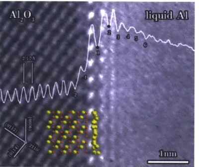
Figure 6. TEM image of solid alumina and liquid aluminum interface depicting an ordered liquid layer 1371.
The ordering behavior of fluids at a solid interface has also been imaged using transmission electron microscopy (TEM) [13], [37]. Imaging this layer requires the liquid to have a lower vapor pressure than the ultrahigh vacuum pressure of the TEM. This limits the experiments to liquid metals at high temperatures or requires a TEM environmental chamber to protect the liquid from evaporation under the high vacuum. Additionally, the ordered interfacial layer is so thin (about 1 nm) that image-processing techniques are necessary to confirm that any apparent ordering is not due to imaging artifacts from the TEM [37]. As seen in Figure 6, liquid aluminum exhibits an approximately one-nanometer thick compressed layer at the interface with solid alumina, similar to what was predicted using MD simulations. The liquid ordering effect seen in TEM images has also been confirmed by using nuclear magnetic resonance (NMR) to experimentally determine the thickness of the interfacial layer [38].
1.2.4 Thermal Properties of Interfacial Liquid Layer
When attempting to utilize the ordering effect at the liquid solid interface for CSP applications, the thermal properties of the interfacial layer are crucial. One of the most prevalent topics in literature relating to thermal properties and liquid-solid interfaces is that of deviations in the melting temperature of liquid from bulk values. While the Gibbs-Thomson equation can be
used to predict adjustments in the melting temperature of liquids in macro-scale pores due to surface tension and capillary forces, the understanding of melting temperature of liquids within nano-scale pores and adsorbed to solid substrates is much less developed. Due to the difficulty with experimental measurements at the nano-scale, much of the research on this subject is computational in nature. In Monte Carlo and MD simulations, adsorbed layers on a solid substrate have been shown to melt at a higher, similar, or lower temperature based on whether the attraction of the adsorbate to the substrate is stronger, comparable, or weaker than the attraction to the bulk liquid, respectively [14], [39]. Radhakrishnan, et al. have made efforts to quantify the relative attraction of an adsorbed layer to the substrate versus the bulk liquid [14]. A relative parameter to gauge the strength of interaction, a, is used where a > 1 denotes a strong attraction to the substrate and a higher local melting temperature, a ~1 denotes a comparable attraction between the substrate and the bulk liquid for a similar melting temperature to bulk liquid, and a < 1 denotes a weaker attraction to the substrate than the bulk material and thus a lower local melting temperature. In Figure 7, several simple adsorbates were characterized with respect to silica and graphite substrates. The use of MD simulations to determine the interaction parameter limits the phase diagram to relatively simple fluids that can be difficult and impractical to test experimentally. Nonetheless, the adsorbed interfacial layer shows potential for enhanced thermal properties over the bulk liquid.
Silica Graphite Ar N2 CH4 2 -Ar CO2 Kr CH4 Kr Xe N2 CO2 CC14 C1 HI HCl 1 -HC1H Xe HI--- C69 C6HN CC14 NH3 NNH 3 HH20 H 20
Figure 7. Expected relative change in melting temperature of interfacial layer for various adsorbates with silica or graphite substrate obtained by molecular dynamics simulations 1141.
Melting point manipulation has been studied experimentally in highly porous substrates such as controlled pore glass (CPG), Vycor, and silicon nitride to allow for a high surface area to volume ratio of the substrate, similar to the effect created by using a nanoparticle mixture
[40-42]. By using differential scanning calorimetry and dielectric relaxation spectroscopy, the
melting temperatures of the components of the substrate/adsorbate mixture can be measured. In these studies, a decrease in melting temperature was measured for a fraction of In, CCl4, and
CCl4-C6H5Br mixtures confined in the nanoporous substrate. These results are indicative of a
weak interaction between the adsorbate and the porous substrate. While this behavior may be beneficial for some applications, increasing the thermal capacity of HTFs for CSP applications
require an increased melting temperature of the adsorbed layer, as will be discussed shortly. Although there is strong evidence, both experimentally and through simulations, that an adsorbed layer at the liquid-solid interface does exist and has unique thermal properties, little work has been done to explore its utility in heat transfer fluids for CSP and other thermal management applications. One area that has been explored is the role of the adsorbed layer in increasing the thermal conductivity of nanofluid mixtures. While much of the excitement from initial reports of anomalously high thermal conductivities in nanofluids has been disproven by
using the Hashin and Shtrikman effective medium theory [43], early reports investigated the role that the adsorbed layer at the nanoparticle surface may have in enhanced thermal conductivity
[5], [44]. However, MD simulations indicate that the adsorbed interfacial layer (about 1 nm thick) has no effect on thermal transport properties for simple, monatomic liquids [5]. The reports mention the possibility that more complex liquids will have an adsorbed layer thicker than 1 nm and a different impact on thermal transport within the nanofluid. Further, while the thermal transport properties of the nanofluid remain largely unaffected, it is possible that the thermal storage properties are distinct from the pure fluid, as has been seen in the studies that manipulated the adsorbate melting point within nanopores.
1.3 THESIS OBJECTIVES AND OUTLINE
While concentrated solar power has significant potential to provide clean and renewable electricity generation, the poor thermal properties of high temperature heat transfer fluids create a significant bottleneck for increases in plant efficiencies. Previous attempts at using phase change materials to increase effective heat capacity in fluids have been shown to cause many operational complications and are not yet suitable for high temperature applications. A more robust alternative is to avoid the need for a phase change material by utilizing the energy of adsorption on the surface of solid nanoparticles for thermal energy storage. While few studies have attempted this nanofluid mixture experimentally, numerous studies report that an increase in melting temperature of an adsorbed layer compared to bulk values is possible, a phenomenon that can be harnessed for an increase in the thermal capacity of high temperature solar nanofluids.
By adding a small mass fraction of solid nanoparticles to a high temperature solar HTF, it is
anticipated that the measured heat capacity of the nanofluid can increase due to the adsorption energy at the liquid-solid interface of the nanoparticle, provided that the liquid-solid attraction is sufficiently strong. The objective of this thesis is to experimentally confirm the effect of the liquid-solid adsorption energy on the thermal capacity of high temperature HTFs. The experimentation focuses on differential scanning calorimetry, while x-ray diffraction and thermogravimetric analysis are also utilized. Through this research, key parameters have be identified to optimize the effect and tailor the enhanced temperature range for a variety of thermal fluid applications. With experimental results and modeling efforts, the fundamental
mechanism behind any increases in thermal capacity can begin to be understood. The findings of this work are relevant to potentially increasing the efficiency of CSP plants by creating more effective high temperature HTFs while furthering the understanding of nanoscale heat and mass transfer that may be applicable to a number of thermal systems. The structure of this thesis is
outlined below:
In Chapter 1, the necessity for more efficient solar power was discussed as well as previous efforts at increasing the thermal capacity of heat transfer fluids. Upon reviewing fundamental studies of adsorption at the liquid-solid interface and melting point manipulation at the nanoscale, a hypothesis is presented for enhancing the thermal capacity of high temperature heat transfer fluids by utilizing the adsorption energy on the surface of nanoparticles.
In Chapter 2, approximations for the thermal capacity of nanofluid mixtures are presented using current models and models that have been modified to accommodate adsorption effects. Key parameters are identified for maximizing the utility of adsorption at the liquid-solid interface.
In Chapter 3, the experimental methodology for the studies is explained. This includes the justification for the selection of adsorbate and adsorbent as well as a description of the relevant experimental equipment.
In Chapter 4, experimental results are presented for several adsorbate and adsorbent combinations. The discussion includes details of successful sample preparation, the intricacies involved with experiments using molten salt heat transfer fluids, and analysis of the reliability of experimental results.
In Chapter 5, the data acquired in Chapter 4 is analyzed in more detail. Trends in the data are explained as they relate to the adsorption hypothesis and the consistency with the expected results is discussed.
In Chapter 6, the experiments and analysis presented in the thesis are summarized. Modifications to the original hypothesis as well as suggestions for future experiments are discussed.
Chapter 2
2. Predicting Enhanced Heat Capacity of Nanoparticle
Mixtures
In order to understand the relative significance of the variables in a nanoparticle mixture, it is crucial to make approximations of the expected thermal enhancements by modeling the behavior of the mixture. The information obtained from these efforts will enable the nanofluid that is used in experiments to demonstrate the anticipated enhancement in heat capacity.
2.1 INCREASING THERMAL CAPACITY WITH ADSORPTION ENERGY
Before estimating the increased thermal capacity of nanofluids, it is essential to understand the nature of the enhancement. In light of the previous research presented in Chapter 1, there appears to be a mechanism for increasing the effective heat capacity of high temperature HTFs for CSP applications. When a small fraction of solid nanoparticles are added to a HTF, a thin layer of HTF is adsorbed to the surface of the particles [5]. The scale of this adsorbed layer is reported to be in the single nanometer range; however, the mass fraction of the adsorbed layer may be large for sufficiently small particle sizes due to the high surface area to volume ratio of nanoparticles. If a fluid and particle combination is chosen such that the fluid is more strongly attracted to the particle than it is to the bulk fluid, a local increase in melting temperature is expected for the adsorbed liquid layer. In this instance, a thin adsorbed layer may remain on the surface of the nanoparticles after the bulk of the liquid has melted. If the temperature continues to increase past the bulk melting temperature, the adsorbed layer is expected to desorb (or melt) while the rest of the HTF is in a liquid phase. The energy of desorption should behave similar to an enthalpy of fusion term and will increase the effective thermal capacity of the HTF over the liquid temperature range. While this value is often measured as a fluid's specific heat capacity, the actual mechanism in this case is a combination of sensible heat of the bulk fluid and the energy of desorption at the particle interface. Thus, the term "thermal capacity" is more appropriate than the common "heat capacity" terminology.
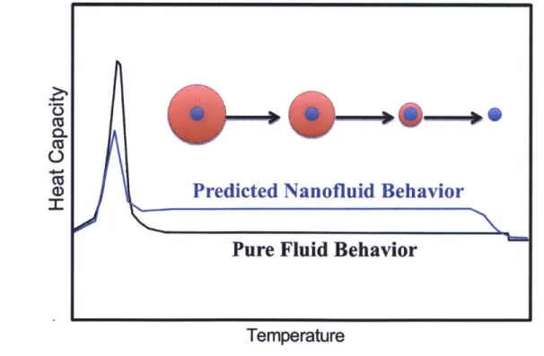
Given this nanoparticle mixture, the current literature suggests that one of two scenarios is likely to occur for an increased thermal capacity. The first case, as demonstrated in Figure 8, mirrors the results of the experiments that observed an anomalous increase in heat capacity of carbonate salt eutectics with ceramic nanoparticles. Once the bulk of the liquid melts, a compressed liquid layer (red) remains adsorbed to the surface of the nanoparticle (blue). As the temperature is increased, the adsorbed layer will slowly desorb with each atomic adsorbed layer requiring additional energy to desorb until the liquid has been entirely desorbed from the nanoparticle. The heat capacity values of the nanofluid (blue) will differ from the pure fluid (black) by having a decrease in latent heat from the adsorbed layer that has yet to melt while experiencing an increase in heat capacity over a finite temperature range. The decrease in latent heat can be seen in the smaller peak of the nanofluid on the left side of Figure 8. The increase in heat capacity occurs while the bulk of the fluid is in a liquid phase and the adsorbed layer is gradually desorbing as the temperature rises. Once the adsorbed layer has completely desorbed from the particle, the heat capacity will have the about the same value as the pure liquid, with a small adjustment for the heat capacity of the nanoparticles that is expected to be negligible for small mass fractions (-I%).
CL
a>
Predicted Nanofluid Behavior
Pure Fluid Behavior
Temperature
Figure 8. Schematic representation of predicted thermal behavior of adsorbed layer in nanofluid based on behavior reported in high temperature carbonate eutectic studies.
If the adsorbed layer in the nanofluid instead has a single increased melting temperature as
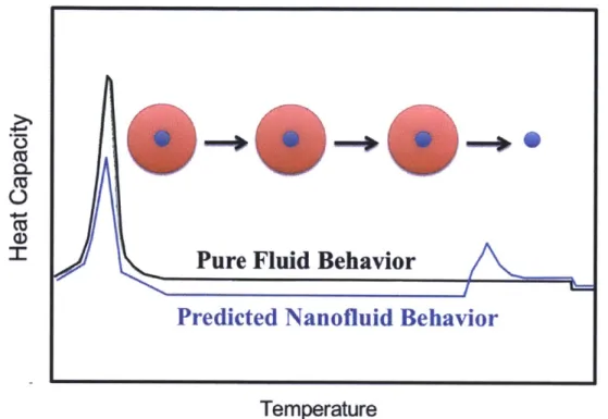
the nanoporous substrate studies suggest, the thermal behavior of the nanofluid will differ from the previous case. The difference in heat capacity values as temperature increases is illustrated in Figure 9. In this scenario, the nanofluid (blue) will exhibit a decrease in latent heat compared to the pure substance (black) as the adsorbed layer remains in a solid-like compressed phase due to the strong attraction to the nanoparticle and has yet to undergo a change of phase, similar to the previous case. Since the nanoporous substrate studies report a single increased melting temperature of the adsorbed layer and not a layer-by-layer desorption, the adsorbed layer will remain adsorbed until the desorption temperature is reached. Before this temperature is reached, the nanofluid will have a lower liquid heat capacity than the pure substance. This is a result of the high mass fraction of adsorbate (red) in the nanoparticle mixture. The adsorbed layer is expected to be in a compressed, solid-like state [5] and thus is expected to have a similar sensible heat capacity to the solid phase of the adsorbate, which in many cases is less than that of the liquid phase [45]. Once the modified melting temperature of the adsorbed layer is reached, a small desorption peak, similar to an enthalpy of fusion term, will be seen as the adsorbed layer completely desorbs from the surface of the nanoparticles. After this point, the nanofluid will return to the heat capacity value that results from a mixing rule of the fluid and the nanoparticles that is nearly identical to the heat capacity of the fluid for small particle fractions.
Ct$
Pure Fluid Behavior
Predicted Nanofluid Behavior
Temperature
Figure 9. Schematic representation of predicted thermal behavior of adsorbed layer in nanofluid based on behavior reported in nanoporous substrate studies.
While there is evidence in literature to suggest that either of these scenarios is possible, one must be chosen for the purpose of approximating significant experimental parameters of the nanofluid. Although the two possible behaviors may exhibit slight differences in thermal properties, the important experimental variables are expected to be the same order of magnitude, placing less significance on which scenario is used for preliminary modeling. The first, layer-by-layer desorption scenario is used in the following sections for basic modeling due to its prevalence in literature with applications for high temperature HTFs for CSP plants [3], [15],
[28], [29], [31], [32].
2.2 MODELING HEAT CAPACITY ENHANCEMENT
In traditional mixing theory, a simple mixing rule is used to predict the thermal properties of a two-component mixture. The rule for heat capacity, C,, of a particle and liquid mixture can be seen in Equation 2. In this equation, p is density and
#
is the mass fraction of particles as defined in Equation 3 where m is mass.CpMxtpre p )Particle + +(pC (1 - p)(pC,)Fluid
(2)
OParticle + (1 - O)P FluidS Particle)
mParticle + mFluid
While this approach for determining heat capacity of a mixture is very common, even for nanoparticle mixtures [1], it is possible that this rule is inadequate in describing the true thermal capacity of a nanofluid. More specifically, the traditional mixing rule does not account for any thermal effects of adsorption at the surface of the nanoparticles. This effect may be negligible for particles with diameters on the order of 100 nm and larger, yet particles with diameters on the order of 10 nm have a high enough surface to volume ratio that the mass fraction of the adsorbed layer is significant [3].
In the instance where the nanoparticles are of this scale, a new approximation is necessary to quantify both the sensible heat of the fluid as well as the adsorption energy of the interfacial layer. First, a new term, y, is introduced to quantify the mass fraction of the adsorbed layer and is defined in Equation 4. The mixing rule is now modified to balance the effective heat capacities of the three components of the nanofluid: the bulk fluid, the nanoparticle, and the adsorbed interfacial layer. The modified equation for effective heat capacity is seen in Equation 5.
= m Adsorbed (4)
mParticle +mFluid + mAdsorbed
Ah
p(pC,)Particle
+ (1 - # - y)(pC, )Fluid + P Adsorption )AdsorbedCMixture - AT (5)
PParticle + (1 - - Y)PFluid + YPAdsorbed
The modified mixing rule presents several new variables related to the quantification of the effective thermal capacity of the adsorbed layer. It should be noted that this modified mixing rule approximation for heat capacity assumes that the adsorbed layer will behave as described in the first scenario in this chapter, where the adsorbed layer slowly desorbs over a finite temperature range before completely desorbing. This temperature desorption range is the A T term in Equation
5. The term JlhAdsorptlion quantifies the enthalpy associated with the phase transition of the adsorbate from a compressed, semi-solid layer to a liquid phase. While it is possible that this desorption enthalpy may be calculated from molecular interaction theory for simple fluids, more complex fluids require that the value be measured experimentally. Measurements of enthalpy of desorption at the liquid-solid interface are inherently difficult to perform due to the nanometer scale of the phenomenon and is best quantified with a differential scanning calorimeter, although often with poor accuracy. If a calorimeter that measures heat flux at the nano-scale could be used, the enthalpy of desorption of an adsorbed layer at the liquid-solid interface could be accurately determined.
In order for this heat capacity approximation to yield useful information about key experimental parameters, a number of assumptions and simplifications are made. The mass fraction of the adsorbed layer, y, is unknown and is estimated. However, since the nanoparticle size, concentration, and thus the available surface area are known, the mass fraction of adsorbate is related to the thickness of the adsorbed layer, a value that has been reported in literature [5].
The density, p, of the adsorbed layer is another unknown. The phase is expected to be a semi-solid state, but experimental evidence for density values is scarce. Based on reports of molecular dynamics and density functional theory at the liquid solid interface [13], [34], the density of the adsorbed layer is approximated as that of the solid phase of the adsorbate.
The effective heat capacity term for the adsorbed layer must also be approximated. In experimental reports of enhanced heat capacity in carbonate eutectic nanofluids, an increase in heat capacity is measured over approximately 50'C [3], [28], [29]. For the sake of this analysis, the desorption temperature range, AT, is assumed to be 50'C as well. Finally, the enthalpy of adsorption, zhAdsorpt1ion, remains unknown and is not easily obtained experimentally or even in simulations for more complex fluids. As an approximation, the enthalpy of fusion of the adsorbate is used instead. Since the particle-adsorbate attraction is expected to be stronger than the solid adsorbate-adsorbate bond, a requirement for the adsorbed layer to exist in a liquid adsorbate environment, any enhancement in heat capacity that is predicted by using the enthalpy of fusion approximation will in actuality underestimate the influence of the adsorbed layer.
-1 nm z 125 - 2 nm cc -5 nm 0. cc - 10 nm 100 75 a> o 50 e25-0~ 10 10 102 10 Nanoparticle Diameter (nm)
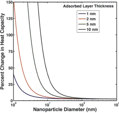
Figure 10. Predicted changes in heat capacity of LiNO3 with 1% A1203 nanoparticles based on a modified
mixing rule in Equation 5.
As will be described in Chapter 5, LiNO3 with 1% by mass A1203 nanoparticles proved to be one of the liquid and particle combinations with the largest adsorption effects. For this reason,
the properties of LiNO3 and A1203 were used for this simulation. The results of the simulation
using the modified mixing rule are displayed in Figure 10.
The trends in Figure 10 suggest a number of important parameters in thermally enhanced nanofluids. As mentioned earlier, the size of the nanoparticles plays a crucial role in any potential increases in thermal capacity. The substantial enhancement in heat capacity with particles below ~10 nm is consistent with reports in literature [3] and lends credibility to the accuracy of the model's approximations. Additionally, the thickness of adsorbed layer is an important parameter. While molecular dynamics simulations suggest that adsorption at the liquid-solid interface extends 1-3 nm from the solid surface [13], all of the current simulations are evaluated for relatively simple monatomic fluids. Studies suggest that more complex fluids may exhibit a thicker adsorbed layer [5]. These complex fluids will behave similar to the green or even black line in Figure 10 and demonstrate substantial improvements in effective heat
capacity over simpler fluids. A strong interaction (from Van der Waals and other forces) between the nanoparticle and the liquid will further increase the adsorbed layer thickness and have a
similar impact on effective heat capacity.
In an ideal scenario, a complex fluid would be mixed with ~1 nm particles to yield the largest increase in effective heat capacity. However, in practice obtaining consistent 1 nm particles while avoiding agglomeration proves very difficult. Focusing on more complex fluids and strong liquid-particle attraction allows substantial improvements in effective heat capacity with reasonable particle sizes of around 10 nm in diameter.
2.3 SUMMARY
In this chapter, information from literature and modeling efforts were both used to isolate important parameters in engineering a nanoparticle HTF with an enhanced thermal capacity. Two scenarios were presented to predict the behavior of an adsorbed layer on the surface of nanoparticles. In the first scenario, the interfacial layer desorbed over a range of temperatures and resulted in an increase in effective heat capacity of the liquid nanofluids. The other case assumes a single desorption temperature for the adsorbed layer and results in an initial decrease in nanofluid heat capacity and a local peak corresponding to the enthalpy of desorption. Both instances have support in literature and the former is used as the focus of preliminary modeling. Although the first scenario was chosen to model, the important aspect of the analysis is to identify the particle size regime required for significant experimental adsorption effects. The model will predict similar parameters for the second scenario since the total enthalpy of desorption, the main parameter that influences particle size and adsorption layer thickness, is the same in both scenarios over the desorption temperature range. While the heat capacity as a function of temperature differs for the two cases, the total enhancement in effective thermal capacity is the same.
A novel modification to the classical mixing rule has been presented to account for the
enthalpy associated with desorbing an interfacial layer. Several assumptions have been made to allow for the modified mixing rule to plotted while altering key variables. Trends in the data
1. Smaller nanoparticle sizes favor greater effective heat capacity. Particle sizes less than 10
nm in diameter are ideal. The key here is providing the maximum surface area for adsorption per unit mass of nanoparticle.
2. Avoiding nanoparticle agglomeration is crucial. Similar to the first point, any agglomeration will decrease the available surface area for adsorption. The use of surfactants may cause complications at high temperatures due to decomposition and may interfere with the adsorption phenomenon. Instead, small mass fractions of nanoparticles should be used to minimize risk of particle agglomeration.
3. Fluid-particle combinations that maximize the enthalpy of adsorption (resulting in a
thicker adsorbed layer) are more favorable. Since the exact mechanism for this phenomenon is difficult to isolate, much of the optimization is left to trial and error. Literature provides two criteria for increasing the thickness of the interfacial layer: choose a fluid that is more complex than a simple monatomic fluid [5] and choose a particle that exhibits a strong attraction to the fluid [14].
4. Fluids that exhibit a large liquid temperature range before boiling or decomposing are desirable. With a larger liquid temperature range, there is a higher chance that the liquid-particle desorption energy will occur while the fluid is in a liquid state. This allows the adsorption behavior to be characterized experimentally and is crucial for the practicality of enhanced nanofluids.
These criteria will be used to help select favorable fluid and particle combinations in Chapters 3.
Chapter 3
3. Experimental Methodology
The experimental design of testing for enhanced heat capacity includes successful sample selection and preparation procedures as well as conducting experiments to confirm the existence of an adsorbed layer and quantity its thermal benefits. The experiments were conducted mostly with differential scanning calorimetry. X-ray diffraction and thermogravimetric analysis were used to further support the adsorption hypothesis. Transmission electron microscopy (TEM) was originally planned as a method of confirming properties of the nanofluids and adsorbed layer but proved to be prohibitively challenging. Difficulties with TEM imaging and recommendations for future improvements are found in Chapter 6.
3.1 SAMPLE SELECTION
Several fluid and particle combinations were chosen for the experiments based on the criteria outlined in Chapter 2 and information found in literature. The following nanofluids are summarized in Table 2. The sample preparation procedure varies with each of the nanofluids and will be discussed in Chapter 4.
For the nanoparticles, the key requirements are small average diameter, stability at high temperatures, and strong affinity to the adsorbate. Nanoparticles of SiO2 and A1203 were chosen to satisfy these specifications. Reports in literature confirm that these ceramics have been shown to sustain an ordered adsorbed layer when in contact with certain liquids, making them a good candidate for the experiments in this thesis [14], [37]. SiO2 nanoparticles with diameters ranging from 5 nm to 15 nm were procured from Sigma Aldrich. A1203 nanoparticles with 10 nm diameters as well as 200 nm diameters, in separate samples, were procured from Nanostructured and Amorphous Materials, Inc. The purpose of the larger particle sizes is to observe the difference in experimental results when the mass fraction of nanoparticles is held constant but the surface area available for adsorption (related to particle size) changes. This will help to elucidate the influence of particle surface area on the thermal capacity of nanofluids.
Several candidate fluids were selected as the focus of the nanofluid experiments. The first fluid was a high temperature carbonate eutectic, Li2CO3-K2CO3 with a 62:38 molar ratio. This eutectic has been used in several studies that report an increased heat capacity in nanofluids [3],
[28], [31], [46] and is a natural choice for the experiments in this thesis. Another fluid used was
Hitec HTS, a commercial molten salt used for CSP applications. The chemical composition is KNO3-NaNO3-NaNO2 with a 44:7:49 molar ratio [20]. In addition to the practicality of increasing the thermal properties of a common commercial HTF, Hitec HTS has a lower melting temperature than Li2CO3-K2CO3 and as a result complications that arose when testing thermal properties at high temperatures were circumvented. While a high operating temperature HTF is valuable in increasing thermodynamic efficiency, feasibility and accuracy of thermal property measurements were a higher priority when evaluating the impact of adsorption at the particle interface and thus a lower temperature HTF was chosen. Finally, LiNO3 was the last candidate fluid. While the melting temperature is higher than Hitec HTS, it is still within a reasonable testing range. Additionally, the other two candidates are eutectics and LiNO3 avoids any issues that may arise from mixing and melting a eutectic salt. The results of these fluids combined with the previously mentioned nanoparticles are detailed in Chapter 4.
Table 2. Summary of nanofluid mixtures used in experiments.
Li2CO3-K2CO3 4880C SiO2 5 - 15 nm 1%, 2%
Hitec HTS (KNO3-NaNO3- 1410C A1203 10 nm 1%
NaNO2) I
LiNO3 2540C A1203 10 nm 1%, 2%
LiNO3 2540C A1203 200 nm 1%, 2%
3.2 DIFFERENTIAL SCANNING CALORIMETRY
A differential scanning calorimeter (DSC) is a piece of equipment used to measure the
thermal capacity of a given sample. DSCs are typically used to measure enthalpy of a phase transformation, onset temperature of a phase transformation, and specific heat capacity. The essential function of a DSC is to measure the heat flux needed to change the temperature of a sample and the resulting data is interpreted to calculate the thermal storage properties. In