Publisher’s version / Version de l'éditeur:
Vous avez des questions? Nous pouvons vous aider. Pour communiquer directement avec un auteur, consultez la
première page de la revue dans laquelle son article a été publié afin de trouver ses coordonnées. Si vous n’arrivez pas à les repérer, communiquez avec nous à [email protected].
Questions? Contact the NRC Publications Archive team at
[email protected]. If you wish to email the authors directly, please see the first page of the publication for their contact information.
https://publications-cnrc.canada.ca/fra/droits
L’accès à ce site Web et l’utilisation de son contenu sont assujettis aux conditions présentées dans le site LISEZ CES CONDITIONS ATTENTIVEMENT AVANT D’UTILISER CE SITE WEB.
Research Paper (National Research Council of Canada. Division of Building
Research); no. DBR-RP-388, 1968-12-01
READ THESE TERMS AND CONDITIONS CAREFULLY BEFORE USING THIS WEBSITE. https://nrc-publications.canada.ca/eng/copyright
NRC Publications Archive Record / Notice des Archives des publications du CNRC :
https://nrc-publications.canada.ca/eng/view/object/?id=36288cb2-fd3d-4d2a-90b2-444115664d64 https://publications-cnrc.canada.ca/fra/voir/objet/?id=36288cb2-fd3d-4d2a-90b2-444115664d64
NRC Publications Archive
Archives des publications du CNRC
This publication could be one of several versions: author’s original, accepted manuscript or the publisher’s version. / La version de cette publication peut être l’une des suivantes : la version prépublication de l’auteur, la version acceptée du manuscrit ou la version de l’éditeur.
For the publisher’s version, please access the DOI link below./ Pour consulter la version de l’éditeur, utilisez le lien DOI ci-dessous.
https://doi.org/10.4224/40001493
Access and use of this website and the material on it are subject to the Terms and Conditions set forth at
Effect of deck on failure temperature of steel beams
Ser
TH1 N21r2
no.
388
c. 2 NATIONAL RESEARCH COUNCIL OF CANADA
ZONSEIL NATIONAL D E RECHERCHES D U CANADA
BLDG
Efect of Deck on Failure
Temperature
of
Steel Beams
by
W. W. Stanzak and T. Z. Harmathy
Reprinted from Fire Technology Vol. 4, No. 4, November 1968
pp. 265-270
Research Paper No. 388 of the
Division of Building Research
OTTAWA December 1968
L'INFLUENCE DU HOURDIS SUR LA TEMPERATURE D'AFFAISSEMENT DES POUTRES D'ACIER AU
COURS D'ESSAIS D'INCENDIE
SOMMAIRE
Les auteurs ont entrepris les travaux analyses dans le present article afin de demontrer que bien que les carac- teristiques d'absorption thermique du hourdis aient une certaine importance pour la duree de resistance h l'incendie, elles ne sont pas suffisamment importantes pour justifier leur inclusion dans les critkres d'affaissement. On a demontre que la temperature des poutres d'acier au moment de l'affaisse- ment lors d'essais d'incendie est pratiquement independante des caracteristiques d'absorption thermique du hourdis.
F I R E TECHNOLOGY
Eflect
of
Deck
on
FT-
42A N A L Y Z E D
Failure Temperature
of
Steel Beams
W. W. STANZAK and T. Z. HARMATHY
Division of Building Research National Research Council (Canada)
I t is generally believed that the heat sink characteristics of decks have a significant effect on the temperature a t which structural failure of steel beams occurs in fire. However, the results of a series of f i e tests fail to support this contention.
T HAS been shown1 that, from well-known deflection and rate of de-
I
flection criteria proposed by Robertson and Ryan: temperature criteria for the failure of steel-supported floors and beams can also be developed. Discussions in various technical groups indicated, however, that there was widespread misunderstanding concerning these temperature criteria. Some people thought that, in addition to some specified temperature, the heatsink characteristics of the deck should also be included in more realistic failure criteria. The work discussed in this paper was undertaken by the authors to show that, even though the heat sink characteristics may be significant as far as the time of fire endurance is concerned, they are not significant enough to justify their inclusion in structural failure criteria.
T E S T S P E C I M E N S
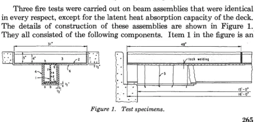
Three fire tests were carried out on beam assemblies that were identical in every respect, except for the latent heat absorption capacity of the deck. The details of construction of these assemblies are shown in Figure 1. They all consisted of the following components. Item 1 in the figure is an
Figure 1. Test specimens.
265
Copyright 1968 NATIONAL FIRE PROTECTION ASSOCIATION 60 BATTERYMARCH ST., BOSTON, MASS. 02110
Printed in U.S.A.
266 Fire Technology
8-in. wide flange, 15-ft 9-in. long beam made of ASTM A36-61T steel and weighing 17 lbs/ft. Four steel pans (Item 2), 31 in. by 48 in. by 5 in. and
% in. thick, were tack welded to the top of the beam. Each contained a 4-in. thick layer of sand (Item 3). The steel beam was protected by two courses of %-in. thick asbestos board (Item 4) assembled with their joints staggered. These boards were fastened to the beam by chrome1 wires (Item 5) about 6 in. apart. The bottom of each pan was protected by %-in. thick Fiberfrax (Item 6), which was cemented to the steel with an inorganic binder.
The steel beam was always simply supported with one end resting on a roller. No restraint was provided against longitudinal expansion.
The temperatures of the steel beams were measured a t three cross sec- tions - a t mid-span and a t the quarter-spans. Seven thermocouples were attached to the mid-span section; the locations of the junctions of these thermocouples are denoted by the letters a, b, c, d, f , g, and h in Figure 1. Only three thermocouples were fastened to the quarter-span sections. The junctions of these were placed a t locations a, e, and g.
The assembly was loaded a t two cross sections, each 3 f t from mid-span. The force was calculated to yield a total stress of 14,000 psi in the extreme fibers of the beam a t mid-span. The load resistance1 of the pans, which, together with the sand, simulated the deck, was disregarded in these stress calculations. I t appeared later, however, that this practice was not fully justifiable. In practical floor constructions, the load resistance of the deck in relation to that of the beam is generally very significant, especially in the final stage of the fire exposure, and depends to a certain degree on the composite action between the beam and the deck.3
The three test specimens differed only in the amount of water contained by the sand forming the deck. In Test No. 1, oven-dried sand was used. In Tests 2 and 3, respectively, the water content of the sand was 5 per cent and 10 per cent by weight. In this way, marked differences in the heat sink characteristics of the deck could be achieved.
T H E O R E T I C A L C O N S I D E R A T I O N S
The temperature criterion of failure for a steel beam can be written in\ the following general form*
where
T,
is to be interpreted as the average temperature of the lower half of the beam.As has been shown in a recent paper,* for ASTM A36 steel
Steel Beams 267
Z = 0.026 u ~ if .u ~
5
15,000 psi, or Z = 1.23 X 10'" 0.0003u if u>
15,000 psi.Since a t u = 14,000 psi, Z = 7.976 X lOI7, from Equation 1 the temper-
ature of failure, T,, is 1,593" R or 1,133" F. As the decks were designed to offer the same load resistance, it was expected that, in all three tests, the failure of the assembly would occur when the average temperature of the lower half of the steel beam exceeded this value, irrespective of the amount of water in the sand.
The experimental points of failure can be conveniently determined from the mid-span deflection versus time records with the aid of the Robertson- Ryan criteria. According to these criteria, the structural failure of floors and beams is imminent when
and
I n the cases examined, L = 186 in. and h = 8 in.; thus the failure criteria
are y 2 5.4 in. and dy/dt 2 28.8 in./hour (or 0.48 in./min).
T E S T R E S U L T S
The fire tests were carried out essentially according to Standard Methods of Fire Tests of Building Construction and Materials (NFPA No. 251).
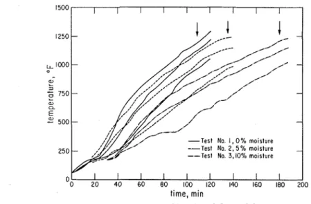
Some information concerning the temperature histories of the steel beams a t mid-span is presented in Figure 2. For each test, three curves are shown. One represents the average temperature of the bottom flange (from thermocouple locations a, b, and c ) ; the second, the average temper- ature of the web (from locations d and f ) ; and the third, the average tem- perature of the top flange (locations g and h). The temperatures recorded from the quarter-spans were essentially equal to those obtained from the corresponding points a t mid-span, except in Test No. 2. During this test, owing to the development of a small gap in the asbestos'board insulation, slightly higher temperatures were recorded for the bottom flange a t mid- span. Because of the occurrence of this localized hot spot a t mid-span, the quarter-span values were also taken into account in the calculation of the average bottom flange temperature for Test No. 2. The arrows in Figure 2 indicate the times of structural failure for the three assemblies.
The deflection and rate of deflection measurements recorded during the tests are reproduced in Figure 3. With the aid of the Robertson-Ryan
268 Fire Technology 1250 - LL.lCQ0 - a, L =
-
750 - ? a, a5
-
500 - --Test No. 1, 0% moisture
--Test No. 2. 5% moisture - --Test No. 3,10% moisture
time, m i n
Figure 2 . Temperature histories of the steel frames.
criteria, the times of failure were determined and are marked with arrows. If the average temperature of the lower half of the beam is defined as
2 (bottom flange temp)
+
web temp3
from the temperature plots presented in Figure 2, the values shown in Table 1 are obtained. I t is clearly seen from this table that, even though the moisture content of the sand had a marked effect on the time of failure, it had practically no effect on T,. This proves in turn that the concept of using some specified temperature of the steel supporting elements as a failure criterion is valid.
It is appropriate, however, to point out some practical difficulties in connection with the calculation of the temperature of failure. The most
time, min
Steel Beams 269
serious among these is that, because of the presence of the deck, the actual load carried by the steel is not known accurately. I n fact, the effective load usually varies with the time of fire exposure. Some test data reported by B1etzacker"dicate that, due to the increasing participation of the deck in transferring the load to the walls, the relief of load in the steel beam may be as high as 80 per cent near the point of structural failure.
TABLE 1. Temperature Criteria of Structural Failure
Moisture Time of Average temperature of the lower Test content failure half of the beam (" F ) N o . ( %) ( m i n ) experimental calculated
1 0 109 1,173 1,133
2 5 135 1,207 1,133
3 10 180 1,177 1,133
Another diaculty is that the two-flange model on which the validity of Equation 1 rests is rarely sufficiently accurate. This model implies that the maximum tensile stresses always occur in the bottom flange of the beam. Recent computer calculations indicate that, as the temperature of the bot- tom flange increases, the neutral axis and the location of the maximum tensile stresses gradually shift toward the colder regions of the beam.
The finite load resistance of the steel pans and the inadequacy of the two-flange model are probably the main reasons why the calculated tem- peratures of failure in Table 1 are 40 to 74" F lower than the experimental values. It is reasonable, however, to draw the following conclusion.
I During fire tests, the temperature (equal to the temperature of the lower
half of the beam) a t the time of structural failure of steel beams carrying decks of similar load resistances (or stiffness) and subjected to similar unit stresses can be expected to be practically independent of the heat sink characteristics of the deck.
N O M E N C L A T U R E
h = depth of steel beam, in.
AH = activation energy of creep, Btu/lb mole
L = length of span, in.
R = gas constant, Btu/lb mole
"
RT,
= average temperature of the lower half of the beam a t structural failure,"
Rt = time, hours unless otherwise specified
y = deflection a t mid-span, in.
Z = Zener-Hollomon parameter, corresponding to the design stress (maximum tensile stress), hr - I
u = stress, psi
R E F E R E N C E S
Harmathy, T. Z., "Deflection and Failure of Steel-Supported Floors and Beams in Fire," Special Technical Publication No. 422, 1967, American Society for Testing
270 Fire Technology
and Materials, Philadelphia, p. 40.
Robertson, A. F. and Ryan, J. V., "Propose? Criteria for Defining Load Failure of Beams, Floors, and Roof Constructions During Fire Tests," Journal of Research o f the National Bureau of Standards, 63C, 1959, p. 121.
3 Pearce, N. S. and Stanzak, W. W., "Load and Fire Test Data on Steel-Supported Floor Assemblies," Special Technical Publication No. 422, 1967, American Society for Testing and Materials, Philadelphia, p. 5.
4 Harmathy, T. Z. and Stanzak, W. W., "Elevated Temperature Tensile and Creep Properties of Some Structural and Prestressing Steels," submitted for publication.
6 Bletzacker, R. W., "Fire Resistance of Protected Steel Beam and Roof Assemblies
as Affected by Stivctural Restraint," Special Technical Publication No. 422, 1967, American Society for Testing and Materials, Philadelphia, p. 63.
6 Harmathy, T . Z., "Creep Bending of Nonuniformly Heated Beams," paper in
preparation.
ACKNOWLEDGMENT: The fire tests were conducted by E. 0. Porteous and J. E . Berndt. The experimental work on which this paper is based was carried out as part of a cooperative research program under a fellowship arrangement between the steel industry of Canada and the Division of Building Research of the National Research Council between 1964 and 1967. The first author was the steel industry's Fellow. This paper is a contribution from the Division of Building Research, National Research Council of Canada, and is published with the approval of the Director of the Division.