DEVELOPMENT OF AN ANALYTICAL DYNAMIC MODEL OF A VIBRO-COMPACTOR USED IN CARBON ANODE PRODUCTION
Fatma Rebaïne
1, Mohamed Bouazara
1, Daniel Marceau
1, Duygu Kocaefe
1, Brigitte Morais
21
Centre universitaire de recherche sur l’aluminium (CURAL), Université du Québec à Chicoutimi, 555, Boul. de l’Université, Chicoutimi, Québec, Canada, G7H 2B1
2
Aluminerie Alouette inc., 400, Pointe-Noire Road, C.P. 1650, Sept-Îles, Québec, Canada, G4R 5M9
Keywords: vibro-compactor, dynamic, anode, frequency
Abstract
The carbon anode quality has a significant impact on the production of primary
aluminum. Their
performance can be evaluated by their various mechanical, electrical, physical, and chemical, properties such as density, electric resistivity, CO
2and air reactivities. The focus of this work is to study the various parameters of the vibro-compaction, which is one of the critical steps in the
process of anode
manufacturing. In this work, a dynamic model of a vibro- compactor is developed. The vibro-compactor is modeled as a rigid mass suspended on springs and dampers and subjected to harmonic external excitation. This model is used to identify the optimal conditions of the vibro-compacting process.
These conditions are obtained through a correlation between the analytical vibro- compaction parameters and data from an industrial vibro- compactor. The use of optimum parameters will help improve the anode
performance and,
consequently, lead to better productivity and reduction on environmental impact.
Introduction The aluminum industries in Quebec consumes alone about 1.27 million tons per year of carbon for anode production. The quality of anodes is widely influenced by the quality of raw materials and the manufacturing process.
Before 1980, the hydraulic presses were used for the fabrication of anodes but now most of the presses have been replaced by the vibro- compactors due to their greater efficiency [1, 2].
However, the control of the various parameters of vibro- compaction is quite relevant because the vibro-compactors
require much more efficient control and maintenance.
During the manufacturing process, the raw materials coke, recycled anodes, butts) are crushed, mixed with pitch and used for forming the paste. After that, they are placed in a vibro-compactor for shaping followed by baking and cooling. The efficiency of each of the manufacturing steps is important to improve the quality and mechanical properties of the anodes.
Vibro-compaction is one of the most critical steps during the fabrication of anodes. If anodes are not well vibrated, their mechanical strength decreases and in turn this causes the premature crack formation. Proper vibration can be achieved by using the optimum values of time, frequency level, load and ensuring a uniform vibration inside the mould.
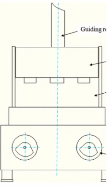
Vibro-compactor The vibro-compactor consists mainly of a vibrating table supported on shock absorbers (vibration isolators), a mould where the anode paste is poured and a follower weight having a loading system which helps to compact the anode paste. Below the vibrating table, there is a rotating motor with eccentric weights that can create a rotation unbalance with a certain excitation frequency thus allowing the system to vibrate. Figure 1 shows a schematic of the key components of vibro- compactor.
Figure 1: Schematic drawing of the vibro-compactor.
Some vibro-compactors also include a vacuum, to have a better efficiency. With the use of vacuum, the apparent densities of green and baked anodes increase by over 0.02 kg/dm
3and 0.015 kg/dm
3, respectively [3].
At the beginning of the vibro- compaction process, the mould is attached to the vibrating table and all the vibrations are propagated under the follower weight which is lowered freely on the paste. When the desired degree of densification is reached with a required vibrating time, the mould is separated from the vibratory assembly and the finished block of anode is pushed laterally outside the mould.
Vibrating table The vibrating table is one of the most important vibro- compactor components. The vibration isolator for the table has changed in the course of time. During the initial stages of the development of the vibrating table, the vibration isolator was made of helical steel. Later, it was replaced by a solid rubber block. Now, the compressed air inflatable rubber is used as a vibration
isolator [4] [5]. The vibration of the vibrating table is largely influenced by the calibration of the angle of the eccentric counterweights.
Figure 2 shows the different vibration isolators.
Figure 2: Evolution of different vibration isolators’
with time.
Eccentric counterweights The vibro-compactor also consists of four eccentric counterweights located on the two shafts. Their balances can be changed by changing the angles of unbalance and used to increase or decrease the magnitude of the vibrating load. The two shafts must be in the same orientation to ensure that all the forces act in the vertical direction and the vibration is balanced. The figure 3 shows
these eccentric
counterweights.
Figure 3: Eccentric counterweights drawing.
There must be angles of unbalance at each corner of the vibrating table, sufficient to have reasonably a uniform vibration of the anode paste.
A non-uniform distribution of
angles of unbalance may
cause the formation of non- homogeneous anodes.
1-D dynamic model A vibratory machine, which is mounted on elastic supports always, has a characteristic resonance frequency which depends on the weight of the vibratory machine and the stiffness of the supports. If the machine with a rigid support weighs less, the resonance frequency will be high. Heavy machinery on highly elastic supports will have a low resonance frequency [6]. The second case is the condition used in this study.
Figure 4 shows a 1-D dynamic model of a vibro- compactor developed in order to study the motion of the vibro-compactor and the vibration parameters. The vibro-compactor is modeled as a rigid mass M
Tsuspended on springs k
Tand dampers b
Tand subjected to harmonic external excitation f(t).
Figure 4: 1-D dynamic model of a vibro-compactor.
The total mass of a vibro- compactor can be represented by the equation (1). It represents the sum of the masses of vibrating table, anode, mould and total weight of the cover.
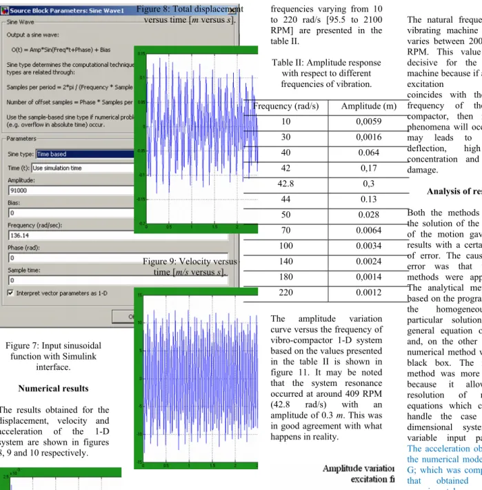
Equations (2) and (3) present the external excitation of a vibratory compactor. The external force can be represented by a sinusoidal
force acting on the whole system.
2
1 m
m M T
(1) where;
M T : Total mass
m 1 : Vibrating table, mould and anodes masses equal to 3650 kg.
m 2 : Cover weigh mass equal to 6270 kg.
) ( sin )
( t f 0 wt
f
(2) and
x k f 0 T
(3) with:
f(t): External excitation force (N).
f
0: Force amplitude (N).
w : Frequency (RPM).
t : Vibrating time (s).
k
T: Total rubber support rigidity (N/m).
b
T: Total rubber support damping (N s/m).
The numerical values of the parameters of the dynamic model are shown in a Table I.
These values were obtained based on data from the article of M. Beilstein et al [1]
.Table I: Dynamic model parameters.
Parameters Values
Total mass 9920 kg
Rubber support rigidity 18.2*10
6N/m Rubber support damping 5000 N s/m
Amplitude 5 mm
Vibrating time 45 s
Frequency 1300 RPM
Analytical model The equation of motion is solved using the following two methods for the model shown in figure 4. First, an analytical approach, which corresponds to a direct
solution of the motion equation, is used. The second approach is based on the use of the Simulink interface of Matlab software. In this section, the analytical model is presented.
The equation of motion can be written as follows:
) (t f x k x b x
M T T T (4) This is a non-homogeneous linear differential equation of second order with constant coefficients. The general solution of this equation can be obtained by the sum of the complementary solution of the homogeneous equation and the particular solution of the equation with the non- homogeneous term (forced response).
If:
x
M T : Inertia force.
x
b T : Viscous resistance force.
x
k T : Elastic force.
Then
n T
n M
t x f w x w
x ( )
.
2 2
(5) All the four terms obtained have the physical dimension of acceleration. The general solution of the system under damped condition is represented below:
) cos(
)
cos(
Ae w X wt
x wnt d
(6)
Analytical results The results obtained by solving the equation (4) are represented in the figure 5.
The maximum displacement was equal to 0.9*10
-3m for an excitation amplitude of 5*10
-3m.
0 5 10 15 20 25 30 35 40 45
-1 -0.8 -0.6 -0.4 -0.2 0 0.2 0.4 0.6 0.8
1x 10⁻³
Time
Displacement
Forced response time