Advanced structural design for
precision radial velocity instruments
The MIT Faculty has made this article openly available.
Please share
how this access benefits you. Your story matters.
Citation
Baldwin, Dan et al. “Advanced Structural Design for Precision Radial
Velocity Instruments.” Ed. Ramón Navarro and James H. Burge.
Advances in Optical and Mechanical Technologies for Telescopes
and Instrumentation II (June 26, 2016.) © 2016 Society of
Photo-Optical Instrumentation Engineers (SPIE)
As Published
http://dx.doi.org/10.1117/12.2235250
Publisher
Society of Photo-Optical Instrumentation Engineers (SPIE)
Version
Final published version
Citable link
http://hdl.handle.net/1721.1/108382
Terms of Use
Article is made available in accordance with the publisher's
policy and may be subject to US copyright law. Please refer to the
publisher's site for terms of use.
Advanced Structural Design for Precision Radial Velocity Instruments
Dan Baldwin
a, Andrew Szentgyorgyi
a, Stuart Barnes
a, Jacob Bean
e, Sagi Ben-Ami
a, Patricia
Brennan
a, Jamie Budynkiewicz
a, Moo-Y
oung Chun
f, Charlie Conroy
a, Jeffrey D. Crane
c, Harland
Epps
h, Ian Evans
a, Janet Evans
a, Jeff Foster
a, Anna Frebel
g, Thomas Gauron
a, Dani Guzman
d, Tyson
Hare
c, Bi-Ho Jang
f, Jeong-Gyun Jang
f, Andres Jordan
d, Jihun Kim
f, Kang-Min Kim
f, Claudia
Mendes de Oliveira
i, Mercedes Lopez-Morales
a, Kenneth McCracken
a, Stuart McMuldroch
a, Joseph
Miller
a, Mark Mueller
a, Jae Sok Oh
f, Mark Ordway
a, Byeong-Gon Park
f, Chan Park
f, Sung-Joon
Park
f, Charles Paxson
a, David Phillips
a, David Plummer
a, William Podgorski
a, Andreas Seifahrt
e,
Daniel Stark
b, Joao Steiner
i, Alan Uomoto
c, Ronald Walsworth
aand Young-Sam Yu
f.
a Harvard-Smithsonian Center for Astrophysics, 60 Garden St., Cambridge, MA 02140;
b Steward Observatory, University of Arizona, 933 North Cherry St., Tucson, AZ, 85721
cThe Observatories of the Carnegie Institution for Science, 813 Santa Barbara St., Pasadena, CA 91101;
d Pontificia Universidad Catolica de Chile, Vicuna Mackenna 4860, Macul, Santiago, Chile;
e University of Chicago, 640 S. Ellis Ave, Chicago, IL 60637;
f Korea Astronomy and Space Science Institute (KASI) 776, Daedeokdae-ro, Yuseong-gu, Daejeon, Republic of Korea
g Massachusetts Institute of Technology, Kavli Institute for Astrophysics and Space Research, 77 Massachusetts Ave.,
Cambridge, MA 02139;
hUCO/Lick Observatory, University of California, Santa Cruz, CA 95064
iUniversidade de São Paolo, Rua do Matão 1226, 05508-900, São Paulo, Brazil
ABSTRACT
The GMT-Consortium Large Earth Finder (G-CLEF) is an echelle spectrograph with precision radial velocity (PRV) capability that will be a first light instrument for the Giant Magellan Telescope (GMT). G-CLEF has a PRV precision goal of 40 cm/sec (10 cm/s for multiple measurements) to enable detection of Earth-like exoplanets in the habitable
zones of sun-like stars1. This precision is a primary driver of G-CLEF’s structural design. Extreme stability is necessary
to minimize image motions at the CCD detectors. Minute changes in temperature, pressure, and acceleration environments cause structural deformations, inducing image motions which degrade PRV precision. The instrument’s structural design will ensure that the PRV goal is achieved under the environments G-CLEF will be subjected to as installed on the GMT azimuth platform, including:
• Millikelvin (0.001 °K) thermal soaks and gradients • 10 millibar changes in ambient pressure
• Changes in acceleration due to instrument tip/tilt and telescope slewing
Carbon fiber/cyanate composite was selected for the optical bench structure in order to meet performance goals. Low coefficient of thermal expansion (CTE) and high stiffness-to-weight are key features of the composite optical bench design. Manufacturability and serviceability of the instrument are also drivers of the design.
In this paper, we discuss analyses leading to technical choices made to minimize G-CLEF’s sensitivity to changing environments. Finite element analysis (FEA) and image motion sensitivity studies were conducted to determine PRV performance under operational environments. We discuss the design of the optical bench structure to optimize stiffness-to-weight and minimize deformations due to inertial and pressure effects. We also discuss quasi-kinematic mounting of optical elements and assemblies, and optimization of these to ensure minimal image motion under thermal, pressure, and inertial loads expected during PRV observations.
Keywords: Echelle spectrograph, precision radial velocity, G-CLEF, GMT, composite optical bench, thermal stability, mechanical stability, low CTE
1. INTRODUCTION
G-CLEF2 is an optical-band, fiber-fed echelle spectrograph that will be a first light science instrument on the GMT3, a
25.4 m diameter optical and near infrared (NIR) telescope under construction in Las Campanas, Chile4. G-CLEF is being
built by a consortium of institutions consisting of the Harvard-Smithsonian Center for Astrophysics, Carnegie Observatories, Pontificia Universidad Catolica de Chile, the Korean Astronomy and Space Science Institute and the University of Chicago. The ability to measure the mass of an Earth-sized rocky exoplanet orbiting in the habitable zone of a sun-like star is a critical science goal for the instrument. For thermal and mechanical stability, G-CLEF is housed within a vacuum vessel mounted at a gravity invariant station (GIS) on the GMT azimuth platform. The spectrograph
features an asymmetric white pupil design5 with a 300 mm diameter beam that is reduced to 200 mm with a pupil
transfer mirror after dispersion by the echelle grating. A Preliminary Design Review was held in April 2015, and the project is currently in the critical design phase. Critical Design Review is scheduled for May 2017, and science operations are planned to begin in 2021.
G-CLEF combined with the GMT will be a powerful instrument for a broad range of investigations in stellar astrophysics, cosmology and astrophysics in general.
2. G-CLEF DESIGN
CLEF’s opto-mechanical design is being developed in response to a requirements flow down from the GMT and
G-CLEF scientific objectives5. G-CLEF Science requirements flow down into the Level 4 G-CLEF Instrument Design
Requirements6. This paper focuses on how the PRV requirements and goals drove the design of the spectrograph optical
bench structure.
2.1 G-CLEF Installation on GMT
The G-CLEF Spectrograph resides at one of the gravity invariant stations (GIS) on the GMT azimuth platform. In order to precisely control instrument temperatures for maximum thermal stability, the spectrograph is mounted inside a cylindrical vacuum vessel which is supported on the GMT azimuth platform. The vacuum vessel is surrounded by thermal control panels which allow the temperature of the spectrograph to be maintained to within 0.001 °K. The spectrograph, vacuum vessel, and thermal control panels are housed within a thermal enclosure on the GMT azimuth platform as shown in Figure 1. The vacuum vessel is quasi-kinematically supported at three points on wire-rope isolators (see Figure 2) to isolate the spectrograph and to minimize print-through of GMT azimuth platform deformations into the spectrograph. The wire rope isolators are compliant relative to the stiffness of the vacuum vessel itself, ensuring mechanical stability of the vacuum vessel and spectrograph under azimuth platform deformations experienced during slewing.
Il
.
Figure 1 – G-C Figure 2 – G-C CLEF Installatio CLEF Three-poi Ø22.5 m on on GMT Azimint Wire Rope Is
muth Platform
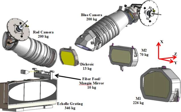
Figure 3 – G-C 2.2 G-The spectrog Figure 4. Th detector7. Figure 4 - Spe Red Camera asphere, 7 el Echelle Gr (300 X 120 Cylindrical M Fold Mirror Fiber Feed and FR converter Red CCD Detector CLEF Spectrogr CLEF Spectro graph optical la he optical paths ectrograph Optic a, f = 500mm, sing ement, 5400 Å to rating 31.6 lpm 00 mm) angin d f/3 to f/8
aph Inside Vacu
ograph Optica ayout is shown
s for the red a
al Layout with R gle 9000 Å (s uum Vessel al Design in
and blue chann
Red and Blue Lig
Dichroic split @ 5400 Å)
nels are both 1
ght Beam Paths
0.8 meters in total length fr
Blue Camera, f asphere, 8 elem
Ellip Mir Beam
rom fiber feed
f = 500mm, single ment, 3500 Å to 54
ptical Pupil Tran ror (f=1600 mm) m Size: 200 mm Parabolic Co (f=2400 mm) Beam Size: 3 to CCD e 400 Å sfer ollimator ) 300 mm
I
h. -i. 2.3 G-A primary d thermal, iner in order to m relative to g excessive im Figure 5 – OptSize and wei The optical b at structural structural pla H = 1.2 m CLEF Optica river of the op rtial, and pressu meet the PRV d
gravity, accele mage motion at
tical Elements an
ight are also cr bench is design supports for atform for the m m al Bench Desig ptical bench de ure environmen design goal. Th erations during the CCD detec nd Light Paths in ritical consider ned to be as sm optical compo major optical a gn esign is to ens nts. Image mo he structure mu g slewing, and ctors throughou n G-CLEF Spec rations, as the i mall and lightw onents and as assembly masse
sure that 10 cm otion at the dete ust ensure that t
d pressure flu ut the duration ctrograph Compo instrument res weight as possib ssemblies. Th es shown in Fig m/s PRV preci ectors must be thermal soaks uctuations do of calibrations
osite Optical Ben
ides on the mo ble while prov he optical ben gure 6. ision is mainta minimized to and gradients, not cause de s and observati nch oving azimuth viding adequate nch structure m L = 3.4 m ained under ch the order of an changes in ori formations lea ions. platform on th e stiffness and must provide m W = 0.9 m anges in ngstroms ientation ading to he GMT. strength a stable
Figure 6 – Opt Table 1 – G-C The optical b to-weight an consists of a supporting th into lower an achieve a min tical Assemblies CLEF Spectrogra Fiber F M1 Echelle M2 Dichroi Red Ca Blue Ca Optical Total bench was des nd to minimize a rectangular-s he optical assem nd upper struc nimum natural s Supported on G aph Masses Assem Feed/Mangin M e Grating ic
amera and Dete amera and Det l Bench (CFRP igned as an in e volume with section outer s mblies. A hori ctural cells. In l frequency goa G-CLEF Optical mbly Mirror ector tector P, Invar, Ti) ternally braced hout violating hell made of izontal panel ru nternal ribs, b al of 50 Hz for Bench d monocoque s the red and b four large flat uns the length bulkheads, and r the assembled Mass (k 10 kg 226 k 346 k 70 kg 13 kg 200 k 200 k 510 k 1575 k shell structure lue channel li t panels with i of the structur longitudinal p d instrument. kg) g kg kg g g kg kg kg kg to maximize s ght beam path internal ribs an re and separate
panels are incl
stiffness- and s hs. The bench nd stiffening e es the primary s luded in the d Z Y X strength-h design elements structure design to
4
oJi'
Figure 7 – G-C Figure 8 – Opt The instrume expansion ra atmospheric CLEF Composit tical Assemblies ent is supporte ates and to iso pressure change Optical Bench
s Supported on O
ed within the v olate the spectr
ges. h Structure (Oute Optical Bench In vacuum vessel rograph structu er Panels Transp nternal Structure on three titani ure from any d
arent for Clarity
s
ium flexures d deformations a
y)
designed to allo
t
)7
4
e
J
1
.0
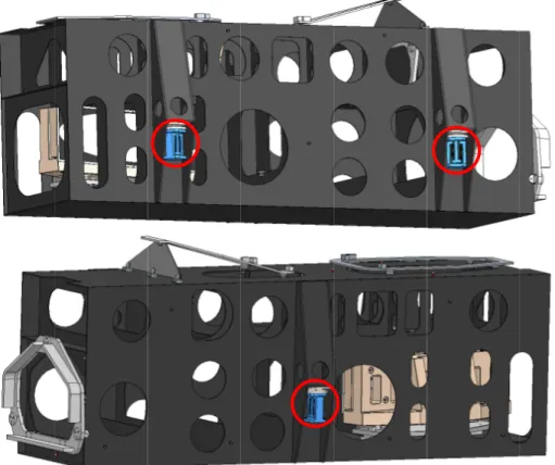
Figure 9 – G-C Optical assem flexured mou for CTE diffe to the opticalFigure 10 – Op
CLEF Titanium
mblies are mo unts which are ferences betwee l bench under t
ptical Bench Inv
Flexure Support
ounted to inva e bonded to the en the mounted thermal soaks a
var Mounting Fra ts
ar frames on t e composite be d optical assem and gradients.
ames for Optical
the optical ben ench laminate mblies and the b
l Assemblies nch (Figure 10 panels. The f bench metering 0). These fra flexure mounts g structure with
ames are suppo s are designed
h minimal defo
orted on to allow ormation
r
\
\
`L
Figure 11 – Bl The mount/l bondlines (se are aligned a Figure 12 – Inlue Camera Fram
aminate joints ee Figure 12). and mounted on
nvar Flexure Mou
me 3-Point Flexu s are designed Invar frames n the frames. unts Bonded to I ured Mount to Pr d to mitigate t are mechanica Internal Optical rimary Optical B the effects of ally attached t Bench Panels Bench Structure high CTE thr
fra,
r
:"
1 a *ü, wrwi _i
a s 44-,11
irrr MiM wga`1Niis'
. if
G-CLEF sys during calibr assemblies d analyses wer achieved. Table 2 – PRV 0.001 °K 0.001 °K Extern Ins M 3.1 Fin A system-lev of this mode instrument in displacement Figure 13 – G-tems engineeri ration and obse due to structur re used to evolv V Error Budgets Environment 0.001 °K Soak K Vertical (X) G K Lateral (Y) G nal Pressure Ch strument Tip/T Moisture Effect nite Element M vel model of th l was to accura n order to deter t results were u -CLEF System L 3. PRV BUD ing6 has develoervation (Table al deformation ve the structur k Gradient Gradient hange Tilt ts Model he G-CLEF opt ately represent rmine deforma used to determi
Level Finite Elem
DGET, FEA A oped a PRV e e 2). The effec ns were analyz ral design evolu
PRV
tical bench and t mass, stiffnes tions resulting ine image moti
ment Model
AND IMAGE rror budget for cts of these en zed and result ution of the ins
Error Budget 2.7 cm/s 1.6 cm/s 3.9 cm/s 10 cm/s 7 cm/s 10 cm/s d optical assem ss, and coeffici from thermal, ions at the dete
MOTION AN r environment nvironments on ing image mo strument to en Dis
mblies was crea ients of therma inertial, and p ectors (IMAD) NALYSIS s the instrumen n translations a otions calculate sure that PRV spersion Image 5 3 7 2 1 2 ated using NX al expansion (C pressure environ ). nt will be subj and rotations o
ed. Results fro performance g e Motion at De 5.4 Å 3.2 Å 7.8 Å 20 Å 14 Å 20 Å Nastran. The CTE) of the as nments. Finite jected to f optical om these goals are etectors purpose ssembled element
- 20.0011 20.0009 20.0008 I20.0007 20.0005 20.0004 20.0003 ,20.0001 20.0000 I19.9999 19.9997 19.9996 Units = C 20.0007 20.0006 20.0005 20.0004 20.0002 20.0001 20.0000 19.9999 19.9998 19.9996 19.9995 19.9994
.
too 3=C 3.2 Im Bisense soft instrument sy to define the file. The fini generated by element outp software dete surface resul displacement analysis, ind wavefront err 3.3 Th The instrume optics within Analyses we image motion Figure 14 – Ve FEA displac thermal soak subjected to which causes mage Motion A tware was devystems subject optical system ite element geo y finite elemen
put data. For ermines the spa
ting from its tr ts at the detect dividual optica rors are not co
hermal Soaks a ent will be mai n 0.001 °K2. Fi
ere run with C n sensitivity to ertical (X-axis) a ement results w k and gradient a lateral (G-C s the greatest a Analysis Using veloped at SA t to mechanica m. The optical s ometry, deflect nt analysis soft r evaluating im atial, dispersio ranslational and
tor are determ al elements are
nsidered.
and Gradients intained in a va inite element a CTE values for
o optical bench
and Lateral (Y-a
were input int t load cases. CLEF Y-axis) amount of imag CfA/SAO Bis AO for the pu l loads and de sensitivities for
tion data, and tware. A text mage motion a on, and focus d
d rotational dis mined by summ e considered t
s
acuum with the analyses were c the composite CTE. axis) Thermal Gr o Bisense soft Results show thermal gradi ge motion at th sense Softwar urpose of quic formations. A r each optical s group data de file is read by at the detector displacements o splacements as ming contributi to be rigid, an ermal controls conducted with e optical bench radients Applied tware to calcul w that the desig
ient. This gra e detectors in t e
ckly evaluatin A Zemax (optic surface in the s fining the opti y Bisense that r (IMAD) for of the beam at s calculated by ons from all th nd higher-ord
ensuring cons h thermal soak h ranging from
d to G-CLEF Sys
late image mot gn is most se adient induces
the critical disp
ng the optical cal design softw system are read
ics are read fro relates the Ze a complete in the detector fo
the finite elem he optics. In G er effects on stant temperatu ks and gradients m -0.4 to +0.3 stem-Level Finit
tion at the det nsitive to opti
bending in th persion directio
response of c ware) input fil d from a second om a punch ou emax data to th nstrument syst or each selected ment analysis. T G-CLEF image PSF, aberratio
ure of the bench s applied to the ppM/°K to de te Element Mod ectors (IMAD ical bench CT he instrument s on (see Figure complex e is read d Zemax utput file he finite tem, the d optical The total e motion ons, and h and all e model. etermine del ) for the TE when structure 15).
CDR IMAD simi Ygrad_3CTE, Static E Displacement - Nodal Min : -78.30, Max : 7E Deformation : Displac I8.800 4.903 4.006 3.108 2.211 1 11,1 -0.481 -1.378 -2.276 -3.173 -4.070 Units angstrom
3CTEbench Ygrad Result
>tep 1
I, Z
3.29, Units = angstrom : ement - Nodal Magnitud[
le0
i_.nriiiii
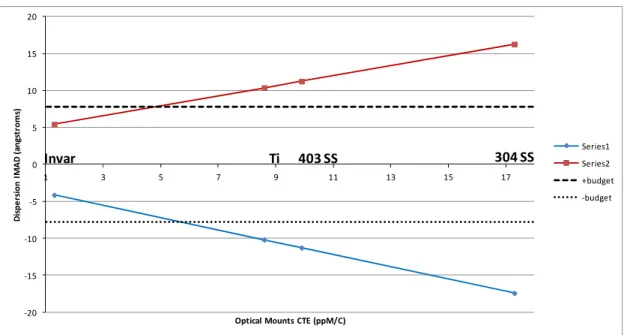
0 SS mummummis Figure 15 – In Figure 16 – Di Dispersion im 16. In orde gradient, ben bench CTE p a CTE rangin fiber cyanate PRV perform composite as nstrument Deform -0.4 Disp e rsio n I M A D ( an gst ro m s) ispersion Image mage motion a er to maintain nch CTE must precluded the u ng from +0.8 to e laminate wit mance to opti s the primary m mation, 0.001 °K -0.3 -0.2 Motion vs. Opti as a function o image motion t be within a r use Invar 36 as o +1.8 ppM/°K th high-modulu cal bench CT material in the o K Lateral (Y-axis -20 -15 -10 -5 0 5 10 15 20 -0.1 Bench CTical Bench CTE
f optical bench ns within bud range of -0.15 s the material f K. The narrow us carbon fibe TE was a majo optical bench s s) Thermal Grad 0 0.1 TE (ppM/K) under 0.001 °K h CTE for a 0. dgeted allowab to +0.20 ppM for the meterin w range of CTE ers and well-co
or consideratio structure. dient, Optical Be 0.2 0.3 Lateral (Y-axis) .001 °K lateral ble for PRV p M/°K. This sen ng structure for E required is ac ontrolled fiber on driving the ench CTE = +0.3 0.4 ) Gradient, ±7.8 l thermal gradi performance un nsitivity of PR r the G-CLEF o chievable for a r volume fracti e selection of 3 ppM/°K blue red +budget -budget Å PRV Budget ient is shown in nder a lateral RV precision to optical bench, quasi-isotropi ion. The sensi f carbon fiber n Figure thermal o optical as it has c carbon itivity of cyanate
A study was also done to determine CTE requirements of optical assembly structures to determine if a higher-CTE material than Invar could be used for these assemblies. Even within a tight range of CTE for the optical bench of -0.1 to +0.1 ppM/°C, Invar 36 is necessary for the metallic structures in the instrument in order to remain within PRV budgets under a 0.001 °C lateral gradient (Figure 17).
-20 -15 -10 -5 0 5 10 15 20 1 3 5 7 9 11 13 15 17 Di sp e rsi o n I M A D ( an gst ro m s)
Optical Mounts CTE (ppM/C)
Series1 Series2 +budget -budget
Invar Ti 403 SS 304 SS
Figure 17 – Dispersion IMAD Sensitivity to Optical Assembly CTE under Lateral Gradient, -0.1 ppM/°C Optical Bench
3.4 G-CLEF Tip/Tilt Relative to Gravity Vector and Accelerations During Slewing
Microgravity accelerations (9.81 μm/s2) were applied to the G-CLEF system level finite element model independently
on x, y, and z coordinate axes to determine deformations and displacements of optical elements. Image motions at the detectors (IMAD) due to these displacements were calculated using Bisense software. The G-CLEF PRV error budget allows 7 cm/sec PRV error for changes in accelerations, equivalent to 14 angstroms IMAD in the critical dispersion direction. G-CLEF sensitivities and allowable accelerations to remain within the allotted PRV budget are shown in Table 3.
Table 3. G-CLEF PDR Design IMAD Sensitivities to Microgravity Accelerations
Acceleration Dispersion IMAD Sensitivity Red Blue PRV Budget Acceleration for PRV Allowable Change in
1 μ-g X, G-CLEF vertical 0.094 Å/μ-g 0.047 Å/μ-g 14 Å 148.9 μ-g
1 μ-g Y, G-CLEF lateral -0.086 Å/μ-g 0.448 Å/μ-g 14 Å 31.3 μ-g
1 μ-g Z, G-CLEF longitudinal 0.499 Å/μ-g -0.531 Å/μ-g 14 Å 26.4 μ-g
The G-CLEF spectrograph experiences changes in acceleration during telescope slewing due to: 1. GMT azimuth axis misalignment with gravity
2. GMT azimuth track height variations 3. azimuthal and centripetal accelerations.
The GMT azimuth axis alignment tolerance with respect to the gravity vector is 116 microradians. For an observation near zenith with 180 degrees of azimuth sweep, a maximum total of 232 micro-g change in acceleration is possible on either the G-CLEF Y- or Z- axes.
B 2
''',.
-20 ,-...
'----.40 time (1 I ---r -,-,...
,
I I r r % r I`.i
minutes from n io neridian) -ZD1 rac --- ZD1 ari - -ZDS rec ZD5 azi1
20 jial imuthal Jial imuthal rmerrrr.a.ary 3( GMT azimut azimuth track during slewin GMT slewin of 13.5 micro CLEF Z-axis Figure 18 – In The maximu due to azimu ΔaYmax = 232 ΔaZmax = 232 The maximu allowables by a factor of 1 gravity is ma Vertical (G-C anchor heigh the 149 micro 3.5 G-The G-CLEF calibrations o suggests that precision rad th track heigh k height tolera ng. g while observ o-g centripetal s), as shown in nstrument Accele um expected la uth track misali 2 g + 22.2 μ-2 μ-g + 17.μ-2 μ-g um changes in y nearly a fact 0, so a levelin aintained to the CLEF X-axis) ht variations areo-g X-axis acc CLEF Sensiti F spectrograph over an observ t a 10 millibar dial velocity (P ht misalignmen ances allow a m ving at GMT de acceleration (G Figure 18. T eration Slewing p
teral and longi ignments, and s g + 13.5 μ-g = g + 8.7 μ-g = G-CLEF later tor of 10. It wa ng system was e accuracy requ accelerations d e in the range o celeration allow vity to Pressu h is housed in vation period. A r change in pre PRV) error bud nts will cause maximum of 2 esign goal 1° z G-CLEF Y-axi hese accelerati past Meridian at itudinal instrum slewing are ad = 268 μ-g (8.6 X 258 μ-g (9.8 X ral and longitu as not seen as designed for t uired to ensure due to azimuth of tenths and h wable for PRV. ure Variation a vacuum vess Analysis of ba essure over a d dget allocation the instrumen 22.2 micro-g Y zenith distance is) and a maxim ions fall off rap
t 1° ZD and 5° Z ment accelerati ded below: X allowable) X allowable) udinal accelera practical to inc the spectrograp PRV performa platform sag b hundredths of a . sel which is su arometric press day should rep for atmospher
nt to tip and/o Y-axis, 17.2 mi (ZD) through mum of 8.7 mi pidly with incr
ZD
ions due to azi
ation exceed th crease the stiff
ph to ensure th ance capability between GMT a micro-g and a
ubject to chang sure data from present 99.9% ric pressure is 2 r tilt as the te icro-g Z-axis c the meridian re cro-g azimutha reased ZD angl
imuth axis ang
he maximum t fness of the spe hat instrument y.
azimuth track are considered n
ges in atmosph m the Las Camp of statistically 20 Å image m elescope slews changes in acce esults in a max al acceleration le.
gle with gravity
to remain with ectrograph stru t orientation re support ancho negligible rela heric pressure panas Observa y likely scenar motion in the di s. GMT eleration ximum (G-y, tip/tilt hin PRV ucture by elative to rs and ative to between atory site rios. The ispersion
along the red camera optical path due to 10 mbar pressure at the vacuum vessel. Bisense software was used to calculate the resulting image motion at the detector based on optical sensitivities.
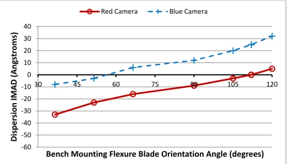
The pre-PDR G-CLEF vacuum vessel design was originally designed slightly oval in cross-section (1.9m x 1.7m) to optimize use of space allocated to the instrument on the GMT azimuth platform. Analysis results showed image motions at the detectors from 10 millibar change in pressure in excess of PRV budgeted allowable by a factor of 17. FEA and Bisense analyses were used to optimize vacuum vessel design to minimize image motions due to pressure variations. Image motion at the detector due to vacuum vessel deformations under the 10 millibar pressure change was reduced from 346 Å to 92 Å by implementing a cylindrical cross-section design. A box-beam structure was incorporated into the bottom of the vacuum vessel to provide a more stable platform for the three optical bench support flexures. This further reduced image motion due to pressure variation to 23 Å, very close to the budgeted allowable of 20 Å. Bench mounting flexure orientations were modified and found to have an influence on image motions at the red and blue detectors due to pressure change, as shown in Figure 19. The bench flexures are designed to be adjustable to allow blade orientation to be optimized for IMAD performance.
Figure 19 – Image Motion due to 10 mbar Pressure Variation vs. Spectrograph Mounting Flexure Orientation
3.6 G-CLEF Sensitivity to Composite Bench CME Shrinkage
The carbon fiber cyanate optical bench laminates will absorb moisture from the atmosphere, which causes the material to expand according to moisture uptake and laminate CME (coefficient of moisture expansion). When the instrument is installed and the vacuum vessel evacuated, this moisture will be drawn out of the composite laminates causing them to shrink. The rate of shrinkage is initially at a maximum but decays over time. A vendor-supplied relationship for
diffusion as a function of time was used to characterize this shrinkage8. The laminate dry-out time required to ensure
that PRV error due to CME effects is within budgeted allowable was calculated using FEA and Bisense software. For the longest anticipated 12-hour calibration/observation/calibration time span, the dry-out time required to ensure PRV precision was calculated to be 123 hours, assuming laminates initially saturated at 50% relative humidity, with 0.15% moisture content. For a 1-hour calibration/observation/calibration time span, the CME effect is within the allowed budget immediately after the instrument is subjected to vacuum in the vacuum vessel, with no dry-out time required.
-60 -50 -40 -30 -20 -10 0 10 20 30 40 30 45 60 75 90 105 120
Disper
sion IMAD (Angs
tr
o
ms)
Bench Mounting Flexure Blade Orientation Angle (degrees)
Figure 20 – Ca We are desi observation. subjected to during observ structure wil gradients. A PRV precisio micro-radian instrument se adjustable de design as sch [1] Szentgyo for the G [2] Mueller, SPIE, 99 [3] Jacoby, McGreg project,” [4] Johns, M (2016) [5] Fűrész, G Proc. SP [6] Podgorsk Spectrog [7] Ben-Am Proc. SP [8] Cohen, L High Re
arbon Fiber Cya
igning and bu We have id changing therm vations. The c ll enable us to A leveling syste on during slew ns, which is le ensitivity to pr esign for these heduled in May orgyi, A., et a Giant Magellan , M., et al., “T 908-374, (2016 G., Bernstein, gor, P. Sharp, R ” Proc. SPIE, 9 M., McCarthy, G. et al., “The PIE, 9147, (201 ki, W. A., et a graph - the GM mi, S., et al., “T PIE, 9908-372, L. M., “Effects esolution Mirro
anate CME Shrin
uilding the G-dentified the m
mal, inertial, an choice of carbo o meet this per
em has been d wing will requ ess than the G ressure change e flexures. We y 2017. al., “The GMT n Telescope (G The Opto-Mech 6) R., Bouchez, R., Szentgyorgy 9908-68 (2016) et al., “Overvi G-CLEF Spec 14).
al., “A Novel MT-Consortium The Optical De
(2016) s of Temporal D or Assembly (H
nkage over Time
4. C -CLEF instrum major structura nd pressure env on fiber cyanate rformance goa designed for th ire maintaining GMT azimuth es may be easil e are confiden REF T-Consortium L MT),” Proc. SP hanical Design A., Colless, M yi, A. and Wall ).
iew and status ctrograph Optic Systems Engi m Large Earth F esign of the G Dimensional In HRMA)” e, Initially Satura ONCLUSION ment to meet al design chall vironments at i e composite m al while being he instrument b g instrument o axis alignmen ly tuned with b t that the G-C FERENCES Large Earth Fi PIE, 9908-76, n of the GMT-M., DePoy, D., ls, B., “Instrum of the Giant M cal Design: An ineering Appro Finder (G-CLE G-CLEF Spectr nstability on th ated at +0.15% M NS a PRV preci lenges to mee its mounted lo materials as the g subjected to based on analy orientation rela nt tolerance to bench support CLEF team is inder (G-CLEF (2016). -Consortium L Espeland, B., mentation Prog Magellan Teles n Update to the oach to the De EF),” Proc. SPI
rograph: The F he Advanced X Moisture Conten ision goal of et this goal w cation on the G primary mater microKelvin s ysis results sho ative to the gra o gravity. An
flexure orienta on track to pr
F): An Optical Large Earth Fin Jaffe, D., Law gress at the Gia
scope Project,” White Pupil E esign of a Prec IE, 9147-333, ( First Light Inst X-ray Astrophy
nt
10 cm/s for while the instru
GMT azimuth p ial in the optic soaks and tem owing that mai avity vector w nalysis has sho ations, which l resent a robust l Echelle Spec nder (G-CLEF) wrence, J., Mar ant Magellan Te ” Proc. SPIE, 9 Echelle Configu cision Radial V (2014).
trument for the ysics Facility (A multiple ument is platform cal bench mperature intaining within 26 own that led to an t critical trograph ),” Proc. rshall, J., elescope 9906-37, uration,” Velocity e GMT,” AXAF-I)