Publisher’s version / Version de l'éditeur:
Vous avez des questions? Nous pouvons vous aider. Pour communiquer directement avec un auteur, consultez la première page de la revue dans laquelle son article a été publié afin de trouver ses coordonnées. Si vous n’arrivez pas à les repérer, communiquez avec nous à [email protected].
Questions? Contact the NRC Publications Archive team at
[email protected]. If you wish to email the authors directly, please see the first page of the publication for their contact information.
https://publications-cnrc.canada.ca/fra/droits
L’accès à ce site Web et l’utilisation de son contenu sont assujettis aux conditions présentées dans le site LISEZ CES CONDITIONS ATTENTIVEMENT AVANT D’UTILISER CE SITE WEB.
Paper (National Research Council of Canada. Division of Building Research); no.
DBR-P-854, 1979
READ THESE TERMS AND CONDITIONS CAREFULLY BEFORE USING THIS WEBSITE. https://nrc-publications.canada.ca/eng/copyright
NRC Publications Archive Record / Notice des Archives des publications du CNRC : https://nrc-publications.canada.ca/eng/view/object/?id=d99a7c0c-20fb-4289-af66-72880cf5931e https://publications-cnrc.canada.ca/fra/voir/objet/?id=d99a7c0c-20fb-4289-af66-72880cf5931e
NRC Publications Archive
Archives des publications du CNRC
This publication could be one of several versions: author’s original, accepted manuscript or the publisher’s version. / La version de cette publication peut être l’une des suivantes : la version prépublication de l’auteur, la version acceptée du manuscrit ou la version de l’éditeur.
For the publisher’s version, please access the DOI link below./ Pour consulter la version de l’éditeur, utilisez le lien DOI ci-dessous.
https://doi.org/10.4224/40001776
Access and use of this website and the material on it are subject to the Terms and Conditions set forth at
Design to cope with fully developed fires
Sef
Ser
Tm
I~ 2 1 h
,
National
Rasearch
Council of Canada
,,
-854
-Conseil
national
de
recherches
du
Canada
IRC PUB
'
:SIGN
TO COPE WITH FULLY
-
DEVELOPED FIRES
by T. 2. Harmathy
Replnted from
4rnwI~a17 %rely for Tesl~ng snd Mafar~als SKIBI Tccnn~cal Pubtrcat~on No C35
1979 7 8 Q
Comme les rnatikes combustibles d'un bihment sant d6truites par les fTammes dans urn proportion d'envlrm 80 B 90 p. cont dumi la Mrlode la plus actlve d'un Incendle, une atlention parllcullere dolt elre port& awx conditions prbdorn~nanles dunnt cetts Mriode de pleina cornbuslion lors de b
c o n w t m das b5timsnts an vue de la %4curll8 i n m d m Cesi a pour but de redu~re les risques de la
prcpagation du leu d do la lum&
a
I'exterleur du compartfment au leu. L'artlda pesenle an &tall Iespar7tcularil.k des incendle dam les compmllmsnts au leu, les factsun q u ~ la Menninenf let tes divm
Copyright
American Society for Testing and Materials 1916 Race Street, Philadelphia, Pa. 19103
1979
Design to Cope with Fully Developed
Fires
REFERENCE: Harmathy, T. Z., "Design to Cope with Fully Developed Fires," Design of Buildings for Fire Safety, ASTM STP 685, E. E. Smith and T. Z. Harmathy, Eds., American Society for Testing and Materials, 1979, pp. 198-276.
ABSTRACT: Since 80 to 90 percent of the combustible contents of building compart- ments are consumed during the period of fully developed f ~ e , the conditions that are expected to prevail during this period should be given special attention in the design of buildings for fire safety. The primary purpose of such design is to lessen the danger of spread of fire and smoke beyond the confines of the fire compartment. To provide a sound basis for the design, the characteristics of compartment fires, the factors that determine them, and the mechanisms by which fire and smoke spread through the building are discussed in detail.
The most common method of protecting buildings against fire spread is compart- mentation by fire-resistant boundary elements. The shortcomings of the conventional practice offire resistance allotment are analyzed and the principles of a recommended practice, referred to asfire tolerance design, are described.
Information on the fire resistance of building elements is usually obtained by stan- dard tests conducted on replicas of the elements. The meaning of the test results, however, is often unclear. It is becoming more and more acceptable to procure fire resistance information either by analytical and numerical studies, or by the use of extension and prediction formulas, graphs, and tables, many of which are reproduced for the designers' convenience.
Owing to fundamental faults in the philosophy of fire resistance testing, information on fire resistance, either from tests or other means, cannot be directly utilized in the fire tolerance design. Methods of conversion between fire resistance and fire tolerance are presented, and techniques of designing for fire tolerance in stagnant and spreading fires, without resorting to fire resistance information, are outlined.
Because of the prominent role that convection plays in the spread of fire and smoke, design for fire tolerance does not provide the complete answer to fire safety. The use of self-closing doors, cavity barriers and fire stops, and flame deflectors, that cut off the paths of convective fire spread, is an essential part of the overall fire defense scheme.
An effective way of attacking the problem of spread of smoke is the pressurization of the principal shafts of the building. The danger of spread of both fire and smoke is greatly reduced by fire drainage.
The need for expert knowledge in the design for fire safety is emphasized.
KEY WORDS: active and passive defense, air flow factor, calculation of fire resistance, characterization of fires, compartmentation, compartment ventilation, composite slabs, concrete constructions, convective fire spread, creep concept, critical air flow, critical
'
Senior Research Officer, Fire Research Section, Division of Building Research, National Research Council of Canada, Ottawa. Canada K I A 0R6.temperature, dividing elements, effect of moisture, estimation of fire resistance, examples of safety design, fire duration, fire drainage, fire load, fire load concept, fire resistance, fire resistance allotment, fire severity parameters, fire spread, fire temperature, fire test philosophy, fire tolerance, fire tolerance design, flame deflectors, fuel-surface control, fully developed fires, key elements, leakage air currents, penetra- tion heat fluxes, periods of fire, pressure in buildings, pressurization of buildings, pre- stressed concrete, protected steel, rate of burning, refuge areas, reinforced concrete, self-closing doors, slab-like constructions, smoke dilution, spread of smoke, stack effect, steel constructions, stress-modified temperature, unprotected steel, ventilation control
Nomenclature
The units listed below must be used in the formulas of this paper.
a Distance of steel from fire-exposed surface, m (ft) A Area; surface area; cross-sectional area, m2 (ft2)
b Breadth; height, thickness; separation, m (ft)
c Specific heat, J/kg
-
K (Btu/lb R)C (with subscript) constant of various dimensions C Heat capacity, J/m
-
K (Btu/ft R)d Distance (Fig. 11), m (ft)
D "Developed" heated perimeter ( ~ i ~ s . 10, 16), m (ft) e Factor, dimensionless
f Yield strength in tension, N/m2 (lbf/ft2) f ' Compressive strength, N/m2 (lbf/ft2)
g Acceleration due to gravity, = 9.8 m/s2 (4.17 X
lo8
ft/h2) G Total fire load, kg (lb)h Height of window, m (ft)
h Heat transfer coefficient, W/m2
-
K (Btu/ft2. h R)H Height, m (ft)
AH Heat of combustion, J/kg (Btu/lb) i = 1 , 2 , 3 ,
...
k Thermal conductivity; without subscript: average thermal conduc- tivity, W/m e K (Btu/ft e h e R) I Length of flame, m (ft) L Thickness; span, m (ft) m Moisture content, kg/kg (lb/lb) M Bending moment, m N (ft , lbf) n Exponent, dimensionless p Pressure, N/m2 (lb/ft
-
h2)2 Ap Pressure difference, N/m2 (lb/ft. h2)P Perimeter of building, m (ft)
q Penetration heat flux, W/m2 (Btu/ft2
-
h)-
q Temporal average penetration heat flux either during the fully de- veloped period of real-world fires or during standard test fires; with- out subscript: that averaged spacially for all compartment bound- aries; with subscript: that for an individual compartment boundary, W/m2 (Btu/ft2. h)
Q Rate of heat evolution, W (Btu/h)
-
Q Average rate of heat evolution, W (Btu/h)
r Fire resistance, s, h
R
Average rate of burning (pyrolysis), kg/s (lb/h)s Cover thickness, m (ft) t Time; time lapse, s, h A t Time increment, s, h
t* Authoritatively specified minimum period of satisfactory perfor- mance, s, h
T Temperature, K (R)
-
T Average temperature during fully developed fire, K (R)
U
Flow rate in relation to compartment, kg/s (lb/h) V Infiltration flow rate, kg/s (lb/h)w Uniform load per unit length, N/m (lbf/ft) W Pressurization flow rate, kg/s (lb/h)
x Distance from fire-exposed surface, m (ft) z Elevation, m (ft)
CY Equivalent orifice area, dimensionless
0
Orifice factor, = 0.6, dimensionlessy Specific surface, m2/kg (ft2/lb) 6 Factor (Eqs 15 and 16), dimensionless
{ Empirical factor (Eq 21), = 1.05, dimensionless r] Empirical factor (Eq 22), = 0.9, dimensionless 8 Fire tolerance, s, h
K Thermal diffusivity; without subscript: average thermal diffusivity,
m2/s (ft2/h)
h Factor (Eq 26), = 1, 1.15, dimensionless v Factor (Eqs 43 to 45), as defined, dimensionless [ Air flow factor, dimensionless
p Density, kg/m3 (lb/ft3)
a Stefan-Boltzmann constant, = 5.67 X lop8 W / m 2 . K 4 (0.171 X Btu/ft2-h.R4)
T Fire duration; without subscript: that of fully developed fire; with
subscript: nominal fire duration, s, h
4 Volumetric moisture content, m3/m (ft3/ft3)
x
Pressure factor, dimensionlessHARMATHY O N FULLY DEVELOPED FIRES 201 Subscripts a Of air a Of outside atmosphere b Of building b Of base level
c For corridor-room partition
c Of concrete ch Of char cr Critical C For corridor C Of compartment C Capacity
e Of encasement; of encasing material f Of furnace
F Of floor
g Of compartment gases
g Of gaseous combustion products
i For building interior
i For the ith boundary element and its lining material I For or on the side of compartment I
I1 For or on the side of compartment 11 m Maximum
min Minimum
o Pertaining to t = 0; under pre-fire conditions o In moistureless condition
o Pertaining to the z = 0 level
p Of protecting material
pf For the postflashover period
r Under standard fire resistance test conditions R For room
s For shaft-corridor partition
s For steel
S For shaft
t Total for the compartment
U
For uncompartmented space v Of volatile decomposition products w For outside wallw For water W Of window
1 For monolithic slab (Eq 48)
2 For double-layer configuration (Eq 49) A Between flashovers in compartments I and I1
Superscripts
0, 1, 2, 3,
. . .
,
j, j+
1,. .
.,
for the time level t = 0, At, 2At. 3At,. . .
,
jAt, ( j
+
l)At,. .
.
In spite of the use of detection and suppression devices and special design features aimed at an early abatement of potential fires, occasionally (once in twenty incidents, according to experts) fires do reach the postflashover stage. It is essential, therefore, from the point of view of safety of life and property, to design all buildings for satisfactory performance even for these rare occurrences.
Once a fire in a building space has reached the fully developed stage, chances of saving either the lives of persons trapped there or any of the furnishings are very slim. Consequently, the principal design effort must be directed toward the provision of safety of life and property in the surrounding spaces yet untouched by the fire. The design is successful if it materially contributes to the lessening of the danger of spread of fire and smoke to the rest of the building without undue increase in the cost of the building. The purpose of this paper is to survey critically the various more or less conventional methods now in use for the protection of buildings and their occupants against danger of spread of fire and smoke, and to call attention to some other methods, less known but perhaps more effective or economical than the conventional ones, for achieving the same end.
Three Periods of Fire
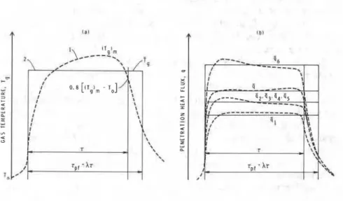
It is usual to divide the course of freely burning compartment fires, based on their temperature histories, into three periods (Fig. l(a)). The first is referred to as the growth period or preflashover period. Because of the relatively low rate of heat evolution, confining the fire during this period to a single compartment can be achieved with moderate effort. In contrast, following flashover, as the compartment opens up to the outside by the breakage of windows, preventing the spread of fire and smoke to other compartments becomes a major effort.
The rate of heat evolution remains high and essentially unchanged during this period of full development (Fig. l(b)); it then drops sharply as the fire enters its third phase, the decay period, during which scattered remnants of the fuel are consumed.
Since professional help by fire fighters cannot be taken for granted, each compartment of a building must be designed to withstand the spread of fire not only for the length of fully developed fire, but also during the decay period. Because usually 80 to 90 percent of the fuel energy is released during the period of full development (Fig. l(b)), this period has always been at the focal point of scientific and engineering interest.
HARMATHY ON FULLY DEVELOPED FIRES 203
FIG. 1-Three periods of fire in terms of ( a ) average temperature of compartment gases. ( b ) rate of heat evolution from the fuel.
Experiments on
Fully
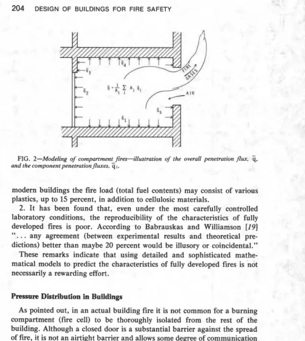
Developed FiresFull-scale and reduced-scale compartment burn-out experiments per- formed in the United States, Japan, and the United Kingdom, and several other countries to gain insight into the characteristics of fully developed fires, now total well over a thousand [ 1 - 1 8 ] . 3 In all these experiments the compartment was modeled as a space perfectly isolated from the rest of the building, and communicating with, that is, receiving air from and dis- charging hot combustion products to, only the outside (usually calm) atmosphere, through openings assumed to represent broken windows (Fig. 2).
Such situations are by no means common in actual fires. Some compart- ments are not separated from the rest of the building by doors. But even those that are so separated will communicate with other building spaces during the fire if the doors are left open by escaping tenants or destroyed by the fire at an early stage. If such situations occur, the pattern of inflow of air and outflow of hot combustion products, owing to pressure differences that prevail in the building at the time of fire, may be completely different from that effectuated in experimental fires. Furthermore, even if the compartment doors remain closed and function satisfactorily throughout the fire, blowing winds may modify the expected flow patterns.
Two further remarks of caution are appropriate.
1. In nearly all experiments performed so far, cellulosic materials (for example, wood, paper) were used as fuel. According to recent surveys, in
FIG. 2-Modeling of compartment fires-illustration of the overall penetration flux,
3,
and the component penetration Jluxes. 3 i .modern buildings the fire load (total fuel contents) may consist of various plastics, up to 15 percent, in addition to cellulosic materials.
2. It has been found that, even under the most carefully controlled laboratory conditions, the reproducibility of the characteristics of fully developed fires is poor. According to Babrauskas and Williamson [I91
". . .
any agreement (between experimental results and theoretical pre- dictions) better than maybe 20 percent would be illusory or coincidental."These remarks indicate that using detailed and sophisticated mathe- matical models to predict the characteristics of fully developed fires is not necessarily a rewarding effort.
Pressure Distribution in Buildings
As pointed out, in an actual building fire it is not common for a burning compartment (fire cell) to be thoroughly isolated from the rest of the building. Although a closed door is a substantial barrier against the spread of fire, it is not an airtight barrier and allows some degree of communication (slight exchange of air or smoke or both) between the fire cell and its sur- roundings.
The vehicles for the dispersion of smoke and, occasionally, flames in a building are those air currents that develop as a result of air leakage in the outside walls of a building. These air currents are especially intense in tall buildings. Since they are usually induced by temperature differences between the interior ahd exterior atmospheres (although wind may also be a factor), they are strongest during the winter heating season. Figure 3(a) illustrates the dominant air currents in a nine-story office building in the winter (with the air-handling system shut down). The building consists of
HARMATHY ON FULLY DEVELOPED FIRES
205
four types of spaces: rooms (R), corridors (C), uncompartmented spaces (U), and stairwells and elevator shafts, referred to here jointly as shafts (S). If the leakage characteristics of the exterior walls are uniform, the infil- tration of air takes places below the midheight of the building. After passing through various partitions, the air enters the shafts, rises to the upper floors, moves toward the outside walls, and exfiltrates to the outside atmosphere. Because of the important role that the stack-like shafts play, the phenomenon is often referred to as air movement by stack or chimney effect. (The small air currents that rise from story to story through the ceilings ark disregarded in the present discussion.)
The intensity of the air currents depends on the extent of leakage through the outside walls and the various interior partitions of the building. Because the flow through small holes or gaps can be likened to flow through orifices, it is usual to characterize the leakiness of a building element by its equivalent orifice area, a , which is the aggregate area of (often invisible) holes, cracks, and gaps, referred to the unit area of that element. An analysis of the situation shown in Fig. 3(a) requires information on three of these equivalent areas: a, for outside walls; a,, for the corridor-room partitions; and a,, for the shaft-corridor partitions.
The pressure differences that exist between the constituent spaces of the building are the direct causes of air movement in a building. Experimental studies of heated multistory buildings [20,21] indicate that the pressure distribution along the height of a simple multistory building can be repre- sented by a series of straight lines (Fig. 3(b)). (In reality, the lines for rooms, corridors, and uncompartmented spaces consist of sections parallel to the line for shafts, and have discontinuities at the ceiling of each story.) They can be described by the following equation4
where
provided that its value at z = 0 is taken as the reference pressure level. In Eqs 1 and 2
4To facilitate the use of both SI and customary inch-pound units, most dimensional con- stants appearing in the equations are denoted by C with a numerical subscript. The values of these constants are given in both units in the text.
HARMATHY ON FULLY DEVELOPED FIRES
207
If
x
= 0, Eq 1 describes the pressure of the outside atmosphere, p,. Withx
= 1 the variation of the pressure in the shafts, p s , is obtained. The values ofx
for the other three types of building spaces, namely X R (for rooms), xc (for corridors), andxu
(for uncompartmented spaces) can be calculated if the three equivalent orifice areas, a,, a,, and a, are known. In general, however, it is sufficiently accurate to use the following valuesSince a, is usually much smaller than either a, or a,, it is permissible (as well as convenient) to assume that the only resistance to the movement of air is that offered by the outside walls of the building. With this assump- tion, the total rate of air infiltration can be calculated as follows [221
Surveys of the leakage characteristics of exterior walls of tall buildings [21,23] indicate that, for lack of more accurate information, a, = 0.0005 is a reasonably conservative selection.
If fire breaks out in the winter below the midheight of a building, and the door of the fire cell is open, the air currents rising in the shafts carry the smoke and disperse it to the compartments on the upper floors. Figure 3(c) shows the pattern of smoke distribution in a nine-story offlce building 10 to 15 min after an outbreak of fire in a space on the first floor. (The smoke contamination of the neighboring spaces is caused by the expansion of gases in the fire cell and by vertical leakage currents mentioned earlier.) If the door of the fire cell remains closed throughout the incident, the smoke contamination of the building is, of course, much less severe, but not necessarily negligible. Even if the gaps around the door are small, large pressure differences may drive a sufficient amount of smoke into the building to present problems.
Because radiation plays a dominant role in the process of fire spread, a closed door usually makes a reliable barrier against the spread of fire. However, if the door is destroyed, the fire will follow the path of smoke, although, understandably, at a much slower pace. Thus, if the fire cell lies below the midheight of a building, the fire will have a tendency to spread toward the shafts, into the building interior. Fortunately, conditions are much more favorable if the fire occurs in one of the compartments on the upper floors. There the fire tends to spread toward the outside bound- aries of the building and, if the flames are prevented from jumping to the floor above through broken windows or other means, there is a good chance that it will die out on reaching the exterior walls.
Theory of Fully Developed Fires
Fujita [2], Kawagoe [3], and Ptchelintzev [4] were the first to recognize that-at variance with Ingberg's concept [I]-the flow rate of air into a burning compartment (compartment ventilation) is just as important a factor in the severity of fully developed fires as the-total fire load. The ensuing theoretical work was pioneered by Kawagoe and Sekine [24,25] and 0deen [26]. Numerous theoretical studies were published subsequently; those by Thomas et a1 [27], Magnusson and Thelandersson [28], Tsuchiya and Sumi [29], this author [30], Babrauskas and Williamson [19], Nilsson [31], and B&m [18] are probably the most comprehensive. The principal aim of these studies was to derive, using fire load, ventilation, and thermal properties of the compartment boundaries as input data, information on the severity of potential fires, usually in the form of their temperature
histories during the periods of full development and perhaps decay. A
variety of assumptions, too many to enumerate, were used to render tract- able the development of the desired information from a formulation of heat balance for the fire cell. Yet, even with simplifying assumptions, the mathematical manipulations usually proved too complex and required the use of computer.
The approach taken by this author [30] was different. Instead of trying to describe the severity of potential fires in terms of their temperature histories, the author introduced three fire severity parameters, easily calculable and yet suitable for characterizing the fire at an accuracy deemed as satisfactory in relation to its reproducibility. The rest of this section will be devoted to a discussion of those parameters.
As stated, the rate of flow of fresh air into the compartment is one of the most important variables on which the severity of fire depends. If the door remains closed and the only communication between the compartment and the outside atmosphere (assumed to be calm) is through broken windows
(Fig. 2), the rate of entry of air can be written as follows
If, however, the compartment door is left open, the pattern of flow of air and combustion products may be completely different from that illustrated
in Fig. 2. For example, the entire window area may be used up by the
entering air and the door area by the outflow of gases, if fire breaks out below the midheight of building in the winter (Fig. 3); the opposite could
HARMATHY ON FULLY DEVELOPED FIRES
209
occur if the fire breaks out above the midheight. The air flow rate resulting from the opening of a door is always higher, at times by a factor of 5 or 6, than that calculable from Eq 4. Since, as will be shown later, in response to a substantial increase of the flow rate of air, the temperature and duration of fire usually decrease (with cellulosic fuel), a left-open door is beneficial from the point of view of the characteristics of fire in the burning compart- ment itself. It is extremely dangerous, however, from the point of view of the spread of fire.
The principal trait of a compartment fire depends on whether the rate of entry of air is lower or higher than a critical value defined as7
where, for conventional furniture, the specific surface of the fuel, y, can be taken approximately as 0.13 m2/kg (0.63 ft2/lb). As will be shown, the rate of burning (or more correctly, the rate of decomposition) of the cellu- losic combustible materials in the -compartment is controlled by either U. (ventilation-control) or by yG (fuel-surface-control), depending on whether the actual flow rate of air is lower or higher (U,),,.
It is convenient to introduce an air flow factor, (, defined as
Thus,
fire is ventilation-controlled if ,$
< 1
(7) fire is fuel-surface-controlled if ( r 1 (8) Experimental data have revealed that the following equations satisfactorily describe the average rate of burning of combustibles during the period of full development.'wind may either increase or decrease the rate of entry of air into the fire cell, depending on whether the cell is located on the windward or leeward side of the building. Unfortunately, since the velocity and direction of wind are incidental variables, the effect of wind cannot be considered.
'when the fuel content includes some noncellulosic materials, the fire load should be interpreted as the mass of calorifically equivalent quantity of wood.
The mass flow rate of the gaseous products out of the compartment is
u,
=K +
U', (11)The average rate of heat evolution from combustible materials during the period of full development can be expressed as follows
-
Q = F(0.932 6 AH,
+
0.068 AH,,,) (12) where AH, 2: 13.4 X lo6 J/kg (5 760 Btu/lb) and AHch = 26.7 X l o 6 J/kg (11 480 Btu/lb). (In these values account is taken of the incomplete oxidation of the carbon atoms.)6 stands for the fraction of heat released by the combustion of the volatile decomposition products inside the compartment. To calculate 6, the average flame length has to be estimated from the following equations
Cos =
then
The three parameters which are claimed to measure the severity (destruc- tive potential) of compartment fires are defined as follows:
1. the duration of fully developed fire, 7,
HARMATHY ON FULLY DEVELOPED FIRES 211
compartment boundaries, averaged spatially over the boundary surfaces, and temporally over the period of full development, and 3. the average temperature of the compartment gases (average "fire temperature")
c,
averaged spatially over the compartment volume, and temporally over the period of full development.The meaning of these parameters is illustrated in Figs. l(a) and 2. As Fig. l(a) shows, the duration of the fully developed fire has been defined, somewhat arbitrarily, as the time lapse between the flashover and the point at which the spatial average temperature rise of the compartment gases drops to 80 percent of its maximum value.
The duration of fully developed fire can be calculated as follows
With the aid of Eqs 4 to 6, 17, and 18 it is possible to express the dura- tion of fully developed fire in terms of the window dimensions and the specific fire load. The following equations are obtained
These equations are applicable to compartments that communicate only with the outside atmosphere (through broken windows). Equation 19 applies to ventilation-controlled, and Eq 20 to fuel-surface-controlled con- ditions. These two equations were used to prepare Table 1 which gives the duration of fully developed fires for selected values of the ratio of window area to floor area, Aw/AF, the specific fire load, G/AF, and the window
l o ? l o Kilo?
height, h. Since, to admit sufficient daylight, Aw/AF is usually chosen larger than 0.1, only the encircled values in Table 1 are of practical im- portance. Clearly, for the range of realistic fire loads (20 I G/AF 5 40 kg/m2; 4.1 I G/AF I 8.2 lb/ft2), fully developed compartment fires are not expected to last longer than about 0.5 h. In fact, fires burning vig- orously for more than 1 h are almost certain indications of fire spread beyond the original fire cell [32].
The other two fire severity parameters, q a n d
z,
can be obtained by trial-and-error solution of the following two equationsq and ( in these equations are empirical constants close to 1. One may select q = 0.9 and
5-
= 1.05. Furthermore, c , = 1 150 J/kg-K (0.275 Btu/lb R).In Eq 22 the thermal behavior of the compartment boundaries is charac- terized by a single term, k / ~ I / 2 . If, as is usual, the various boundary ele- ments of the compartment are lined with different materials
where
and the subscript i(= 1, 2, 3,
.
.
.) refers to the various boundary elements and their lining materials.In examining the effect of fire on the individual boundary elements, the individual penetration fluxes, rather than the overall penetration flux, are of interest (Fig. 2). The following equation applies
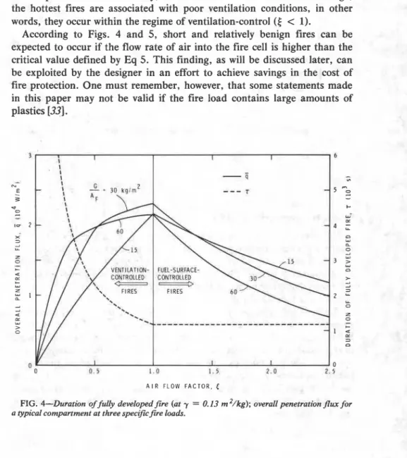
The dependence of the duration of fully developed fire on the air flow factor (for y = 0.13 m2/kg, 0.63 ft2/lb; a typical value) is shown in Fig. 4 (right scale). The same figure also shows how the overall penetration flux varies with the air flow factor (left scale), at three values of the specific
fire load, namely, G / A F = 15, 30, and 60 kg/m2 (3.1, 6.1, and 12.3 lb/ft2). Although these latter curves were developed for a specific compartment, similar to that used by Butcher et a1 [12,13] in their full scale experimental studies, they can be regarded as typical in both shape and numerical value. It is significant that the maximum of ij always occurs at ,$ = 1 and that the value of the maximum depends only slightly on the specific fire load.
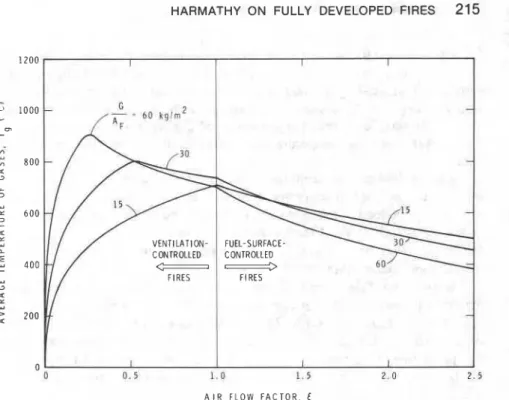
Figure 5 depicts the variation of the third fire severity parameter, the
spatial and temporal average temperature of the compartment gases, with the air flow factor for the same compartment and at the same three values of the specific fire load. Clearly, unless the fire load is lower than average, the hottest fires are associated with poor ventilation conditions, in other words, they occur within the regime of ventilation-control
(E
<
1).According to Figs. 4 and 5, short and relatively benign fires can be expected to occur if the flow rate of air into the fire cell is higher than the critical value defined by Eq 5. This finding, as will be discussed later, can be exploited by the designer in an effort to achieve savings in the cost of fire protection. One must remember, however, that some statements made in this paper may not be valid if the fire load contains large amounts of I plastics [33].
- 0 0 . 5 1. a 1 . 5 2 . 0 7 . 5
A I R F L O W F A C T O R , (
FIG. 4-Duration of h l l y developed fire (at y = 0.13 m '/kg); overall penetration
Jlwc
for a typical compartment at three spectjic5re loads.A I R F L O W F A C T O R . E
FIG. 5-Average temperature of fire gases for a typical compartment, at three specific fire loads.
Means of Characterizing a Fire
The severity of real-world compartment fires is usually characterized by their temperature histories [25,28,34,35]. (This probably originated from the standard fire test practices, in which a temperature-time curve is the manifestation of the severity of test fire.) Unfortunately, close examination will reveal that attaching an exclusive significance to the temperature history of fire is not fully justifiable.
The basic weakness of this practice can be understood through a simple example. Assume that fire breaks out in two compartments that are identical in all respects, except that one is lined with good, the other with poor, heat conductors. Obviously, the temperature in the latter compartment will reach higher values than in the former and, if judged on this basis, the fire will appear to be more severe. Yet, exactly because of the better insulation provided, the rate of heat penetration into the compartment boundaries will be lower and consequently the damage caused by the fire less.
That the temperature of a fire is not necessarily an indication of its severity can also be understood from a comparison of Figs. 4 and 5. These figures show that while the highest fire temperatures often occur well within the ventilation-controlled regime, that is, at some
5
<
1, the heat penetration into the compartment boundaries is always the most intense at the point of transition between the ventilation-controlled and fuel-surface- controlled regimes, that is, at [ = 1.In addition to these, there are also some practical reasons for criticizing the prevailing practice. The generation of the temperature-time curve (to be used as a design basis) for a compartment is the result of complex, computer-executed calculations. The shape of the curve depends a great deal on the thermal properties assigned to the compartment boundaries, namely, on information which normally is expected to be among the end products of the design deliberations. To circumvent this difficulty, it has been usual to develop all-purpose families of fire-temperature versus time curves based on typical properties-strictly valid only for a few compartment lining materials-and to regard these curves as dependent on two param- eters only: fire load and ventilati~n.~
In the light of these considerations, adopting the practice of characterizing a fire by the three parameters introduced in the previous section is not only in the interest of accuracy but also of practicality. After further examining the import of these parameters, one finds that of the three only two are really needed: the duration of fully developed fire, 7, and the overall pene-
tration flux,
7.
Occasionally, to explain the relation between the fire severity parameters and the fire-temperature versus time curves, it may be necessary to select the average gas-temperature,c,
instead ofq,
as a mate for 7 . But using for characterizing the fire can be objected to on thesame ground as was the practice of using the complete fire-temperature versus time curve.
Equations 21 and 22 show that knowing the thermal properties of the lining materials is also a prerequisite to the calculation of
q.
The problem created by this requirement is analogous to that encountered in the predic- tion of the complete temperature history of the fire. Sinceq
(and also-
T,) are evaluated by simple calculations, however, the designer can afford
to start speculating with some crude values of the thermal properties and modify them as the design progresses. Even further, in preliminary calcula- tions, he may neglect consideration of the thermal properties of the com- partment boundaries and select
7
as 10 to 50 percent ofa / ~ ~ .
(Higher values usually pertain to lower values of5 . )
In designing the compartment boundaries for proper performance, the
'1t may also be added that these all-purpose families of fire-temperature versus time curves have been based on the assumption that all fires are ventilation-controlled. Recent fire load surveys indicated that this assumption is not valid in the majority of actual fires.
HARMATHY ON FULLY DEVELOPED FIRES 217
heat fluxes penetrating the individual boundaries must also be known. This information is obtained with the aid of Eq 25.
To account for the decay period of the fire, it is advisable to apply an empirical correction to the value of T and define a nominal duration, rPf,
for the entire posfflashover (fully-developed plus decaying) fire as
X = 1.15 is recommended for cellulosic materials and char-forming plastics. For non-charring plastics and liquid fuels, X .= 1.
In summary, the three ways of characterizing posfflashover fires are illustrated in Fig. 6. Figure 6(a) shows the temperature-based characteriza- tion, either by a complete fire-temperature versus time curve, or by the fire severity parameters, and T. Figure 6(b) depicts the preferred method,
characterization by
q
and T, as well as by the individual penetration fluxes:- - -
ql, q2, q3,
. . .
applicable to various elements of the compartment boundary. (It is seen that q ,q
I , q 2 , q3,.
. .
represent time-averaged values of quan-tities that are subject to moderate variation.) Fire Load
Even though the characteristics of potential fires are amenable to cal- culation, it may often prove difficult to gather the information to be used as input data. The difficulty in estimating the rate of entry of air into the
FIG. 6-Means of characterizing fire: ( a ) temperature-based ~ ~ r a c t e r i z a t i o n : Curve I-by complete temperature versus time curve; Curve 2-by parameters Tg and r , (b) characterization by parameters
3
and r , and by the individual penetration fluxes 3 I , 3 2,33,
.
. . (The dashedfire cell has already been discussed. Fortunately, that difficulty can be circumvented by a simple design expedient: by specifying self-closing compartment doors.
Another major difficulty is the assessment of the fire load. Surveys conducted in various countries [36-441 revealed that the type of occupancy is the most important factor in the magnitude of fire load. It was also found, however, that even for similar occupancies the specific fire load may vary markedly in a seemingly unpredictable fashion.
A few results of fire load surveys conducted in Sweden are listed in Table 2. (It was necessary to use some assumptions in deriving the informa- tion presented therein, for in the original Swedish tabulation [45] the fire load was expressed in terms of heat of combustion referred to the total internal surface area of compartment.) For office spaces the Swedish findings have been corroborated by data published in the United Kingdom [40]. Recent surveys in the United States [44] seem to indicate, however, that office fire loads may be up to 50 percent higher in the North American continent.
Bryson and Gross [39] pointed out that some combustible objects, for example, those placed in closed cupboards, or in filing cabinets, are not accessible to the fire and, therefore, the effective fire load is often lower than the aggregate value of the combustible contents. Arnault et a1 [17] found that some massive combustible items, piled up books or journals in particular, would not burn readily even if accessible to fire, and would leave an unburned residue that may amount to one third of their original mass. Consequently, in office rooms and libraries, where the paper products make up 70 to 95 percent of the total fire load, the effective fire load may be considerably lower than the values indicated by statistics.
Owing to the substantial spread in the available fire load data, it is somewhat difficult to know how to define the specific fire load to be used as the basis of design considerations. If the average values are selected, the design may be inadequate in half of the cases; if a value much higher than the average is chosen, the cost of fire protection may be unduly increased. In Sweden the accepted design procedure is to choose a fire load which is
TABLE 2-Information onfire load [45]. Specific Fire Load, G/AF kg/m2
Standard
Occupancy Average Deviation 80% Level
Dwelling 30.1 4.4 32.3
Office 24.8 8.6 30.0
School 17.5 5.1 20.9
Hospital 25.1 7.8 31.8
HARMATHY ON FULLY DEVELOPED FIRES 219 applicable to 80 percent of each particular building occupancy considered. (These fire loads are also listed in Table 2.) Many believe, however, that the design value of the fire load should be specified on the basis of life safety considerations or, as Lie advocates [ 4 6 ] , on the basis of cost-benefit studies.
Clearly, there is an urgent need for more fire load surveys and for devel- oping a philosophy of applying the information resulting from the surveys.
Fire Resistance
I
The primary purpose of the compartmentation of buildings is to provide I functional units and to secure some degree of privacy to the occupants. I From the point of view of fire, however, compartmentation is regarded as
the principal tool in breaking up the total building volume into small cells I where fires can be localized and possibly suppressed. To prevent a fire from
spreading from one compartment to another, the compartment boundaries
I
imust
be made sound enough to function as effective fire barriers. The I method of defense against the spread of fire that relies on compartmentationand on the satisfactory fire performance of usually immobile building components (walk, floors, doors, etc.) is often referred to as a passive defense method, and is contrasted with the active defense methods which place more emphasis on the use of equipment.
There are two problems intrinsic to the passive defense technique: how to decide on what constitutes the minimum period of satisfactory per- formance in fire, and how to judge the acceptability of the compartment boundaries for the specified performance.
Decisions on the minimum period of satisfactory performance are usually made authoritatively by the writers of building codes; these decisions are largely based an the fire load concept advocated by lngberg I l j more than 40 years ago. According to this concept, the severity of compartment fires increases steadily with the increase of the specific fire load and, therefore, so also should the fire performance requirements.
As to the latter problem, the common practice at present is to judge acceptability of a compartment boundary for a specified minimum per- formance on the basis of its fire resistance, a property with the dimension of time, determined, as a rule, by subjecting a representative specimen of the construction to a standard fire test, for example, ASTM Fire Tests of Building Construction and Materials
(E
119).For those not fully conversant with fire protection terminology, it is interposed here that the term fire resistance denotes the time elapsed between the start of a fire test-that is, exposure of the test sample on one side (except columns which are usually exposed on all four sides) to the atmosphere of a test furnace, the temperature of which is controlled to follow a prescribed course, claimed to represent a severe fire-and the
failure of the sample either (a) by a rise of temperature on its reverse (unexposed) side by 139°C (25Q0F) above the initial level, or ( b ) by a rise of temperature in some load-bearing steel component of the sample to a level deemed intolerable from the point of view of structural safety, usually 427°C (800°F) for prestressing steel, 538°C (1 000°F) for steel cores of columns, 593°C (1 100°F) for reinforcing steel, steel beams, or ( c ) by substantial structural damage, such as collapse or formation of through- openings.
By scrutinizing how standard fire tests are conducted and the criteria of failure defined, one will find that the philosophy of fire testing is founded on the following assumptions
1. Compartment fires always develop in a definite manner characterized by a unique temperature history.
2. Fire spreads from one compartment to another by either transmission of heat through, or structural failure (generally collapse) of, a compartment boundary.
3. Fire-resistant compartment boundaries do confine fire to a single compartment; consequently a compartment boundary will never be exposed to fire on both sides.
That the first of these assumptions is untenable is obvious from the discussion presented previously on theory of fully developed fires. Strangely enough, the
weakness
of the second assumption has not yet been fully realized, wen though it has Iong been known that fires rarely spread by heat transmission through, or by calIapse of, a compartment boundary (Fig. 7(a)), but rather by radiation and convection. As illustrated in Fig.7 ( b ) , flames are usually driven by pressure differences from one building space to another, either horizontally, mainly through open doors, or vertically, through ducts, shafts, openings in the ceiling, and flames issuing from windows then jumping to the story above. Ignition by the advancing flames occurs mostly by heat fluxes emanating from the flames. (Of course,
! walls, floors, or entire buildings do collapse occasionally in fires. In such
cases, however, collapse usually occurs after the spread of fire; in other words, collapse is the result, not the cause, of the expansion of fire. As pointed out recently [47,48], exposure of compartment boundaries to fire on both sides may cause conditions that are more serious than those arising from one-sided exposure.)
Clearly, fire-resistant compartmentation, although it has great merits, is in itself no assurance against the spread of fire. Thus, contrary to the third assumption of the test philosophy, compartment boundaries may, and often do, become exposed to fire on both sides, although not necessarily simultaneously. This statement appears even more obvious after reflecting on the claim, made in connection with Table 1, that building fires lasting longer that 1 h are almost certain indications of fire spread. Experience
HARMATHY ON FULLY DEVELOPED FIRES 221 has shown that, in spite of intervention by fire fighters, long fires do occur even in buildings compartmented with fire-resistant boundary elements. In addition to these faults related to the underlying test philosophy, several others mainly of a technical nature have also been noted in the test practice itself [49-531. Among these, the most disturbing is probably that the (time-averaged) rate of heat penetration into the specimen during a standard fire resistance test,
q,,
depends, in addition to the thermal pro- perties of the specimen and the duration of test, on the type of furnace construction (especially on the properties of the lining materials), and on the furnace fuel. These remarks clearly underline the need for expert judg- ment in the interpretation of the results of standard fire tests.In this paper the practice of complying with authoritative decisions in choosing the minimum periods of satisfactory performance, t*, and iden- tifying the periods of satisfactory performance with the fire resistance values, r, developed for the various constructions either by fire tests or by reasoning or calculations based on the fire test philosophy, will be referred to as fire resistance allotment.
Using mathematical symbolism, the preceding discussion can be sum- marized as follows
r
period of satisfactory performance under the following conditions:
(a) severity of fire exposure:
as determined by the standard temperature time curve, by the furnace construction and fuel, and by the specimen materials, and implicitly characterized by
q,,
( b ) satisfactory performance:as defined by the failure criteria of the standard, and
(c) fire exposure:
on one side only (except for columns) and
Equation 28 can be recognized to represent the condition of acceptability.
Dividing Elements and Key Elements
Even though, under real-world conditions, compartment boundaries often are subjected to destructive heating on both sides, the practice of
l ar F I R E S P R E A D
-
B Y H E A T T R A N S M I S S I - F I R E S P R E A D B Y S T R U C T U R F A I L U R EFIG. .7-Mechanisms of$re spread: ( a ) assumed mechanisms. ( b ) actual mechanisms.
judging the acceptability of building elements from tests in which only one side is exposed to fire must not be unconditionally condemned. For a large group of building elements, to be referred to here as dividing elements, which are not essential parts of the principal structural network of the building (although may carry substantial load), extending the performance investigations to two-sided fire exposure would not be justified. Once fire has reached the reverse side of such an element, via any path, its structural failure (for example, collapse) can in no way influence either the further course of the fire or the performance of the building as a whole.
On the other hand, the collapse or major deformation of a key element of a building may result in extensive damage and loss of life and must not be allowed to happen, therefore, even after an eventual spread of fire. Consequently, judging the performance of such key elements from tests employing one-sided fire exposure is clearly not permissible.
Fire Tolerance
There are many who advocate the idea that competent engineers be given a larger degree of freedom in working out the most appropriate measures for the containment of possible fires. It has been suggested that the en- larged engineering freedom include (a) estimation of the expected fire severity, ( b ) decision on whether emphasis be placed on passive or active method of fire defense, and, if the passive method is emphasized, (c)
examination of the performance of the planned compartment boundaries under the relevant conditions, and the making of the decision on their acceptability.
In contradistinction to the fire resistance allotment, the practice involving engineering decisions on the required and expected performance of the compartment boundaries and on the acceptability of the planned boundary elements will be referred to asfire tolerance design. The termfire tolerance,
to be denoted by 8, will be used in a specific sense9 to mean: period of
satisfactory performance under the applicable conditions, as characterized
by one or the other of the quantities,
q,
andE,
determined by either Iengineering studies or by nonstandard fire tests; the satisfactory performance I
being defined either (a) by failure criteria similar to those of the standard I
test methods, lo in the case of dividing elements, or (b) in the case of key
elements, by the same criteria for fire exposure on one side or the other,
I
but by the criteria related to structural failure only, for fire eqposure on
both sides.
i
!The minimum acceptable value of the fire tolerance should obviously be identical with the duration of fully developed fire, with correction to the decay period, as expressed by Eq 26. (See also Fig. 6.)
Again, using mathematical symbolism
r
period of satisfactory performance under the following con- ditions:
(a) severity of fire exposure:
as characterized by either
q,
or (less desirably)E,
(b) satisfactory performance: as defined essentially
(i) by the failure criteria of the standard test methods, in the case of dividing elements,
(ii) by the failure criteria of the standard test for fire exposure on one side or the those criteria of the
relate to structural failure only in both sides, in the case
(c) fire exposure:
(i) on one side or the other, for dividing elements, (ii) on one side or the other and
i elements.
9 ~ h e phrase "fire tolerance" has been coined by the author. Its introduction has been deemed advisable to distinguish the idea conveyed by it from that expressed either by the term "fire resistance" or its synonym, "fire endurance." Much misunderstanding has already re- sulted from the inappropriate use of these two terms. It is hoped that fire researchers and en ineers will adopt the new phraseology.
"Because most failure criteria of the standard tests are subject to criticism on engineering grounds, the designer should use them judiciously.
The condition of acceptability is
Although at this time Sweden is the only country where design for fire tolerance is accepted as an alternative to fire resistance allotment, the movement for its recognition is steadily gaining momentum.
Sources of Information on Fire Resistance Standard Fire Tests
In spite of its apparent shortcomings, the standard fire test is still the principal source of information on the fire resistance of building elements. The problems associated with the applicability of the test results are, how- ever, numerous. Even if the fire test is performed on a specimen which faithfully duplicates all essential features of the construction, many of the service conditions, especially those related to loading and end restraint, are not readily reproducible. It is also realized that it is impossible to subject to fire tests replicas of all conceivable variants of even a single construction and, therefore, applying the test results to constructions which are different in one way or another from the tested specimen is unavoidable.
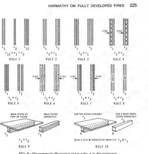
This author presented ten rules [54] which can be used as a crude guide by those charged with making decisions on the applicability of fire test results. These rules are summarized below and illustrated in Fig. 8. Some of the rules are subject to certain limitations, as discussed in the original paper.
Rule I-The "thermal" fire resistance (that is, resistance to heat trans- mission) of a construction consisting of a number of parallel layers is greater than the sum of the thermal fire resistances of the individual layers.
Rule 2-The fire resistance of a construction usually does not decrease with the addition of further layers of materials.
Rule 3-The fire resistance of a construction containing continuous air layers or cavities is greater than that of a similar construction of the same mass, built without air layers or cavities.
Rule 4-The further an air layer is located from the fire-exposed sur- face, the more beneficial is its effect on fire resistance.
Rule 5-The fire resistance of a construction cannot be increased by in- creasing the thickness of a completely enclosed air layer.
Rule 6-Layers of materials of low thermal conductivity are better uti- lized on the side of the construction that is exposed to the test fire.
Rule 7-The fire resistance of asymmetrical constructions depends on which side is exposed to the test fire.
HARMATHY ON FULLY DEVELOPED FIRES
225
11
I\ r I F I2 1 2 r 1 2 ' r 1 + '2 r 2 > r 1 r 2 > r 1 r 2 > r 1
RULE 1 RULE 2 RULE 3 RULE 4
r = r
1 2 r l > r 2 ' 1 + '2 r > r 1 2 RULE 5 RULE 6 RULE 7 RULE 8
BEAM TESTED AS BEAM TESTED FOR THE FLOOR ASSEMBLY FOR A BEAM W H E N
r 1 rr2 BEAM A CAN BE REPLACED BY BEAM B IF r 2 >, r 1
R U L E 9 RULE 1 0
FIG. 8-Diagrammatic illustration of ten rules. r = f i r e resistance.
Rule 8-The presence of moisture, if it does not result in explosive spalling, is beneficial to fire resistance.
Rule 9-Load-supporting elements, such as beams, girders, joists, yield higher fire resistance when subjected to fire tests as parts of floor, roof, or ceiling assemblies than they do when tested separately.
Rule 10-The load-supporting elements (beams, girders, joists, etc.) of a floor, roof, or ceiling assembly can be replaced by such other load-support- ing elements which, when tested separately, yielded fire resistances not less than that of the assembly.
A further problem of major concern is that the standard fire tests were devised to yield information on the performance of separate building elements only; it is well known, however, that failure in fire is often due to interactions between the various units or even between the fire-exposed and unexposed sections of the same element. Some insight into these inter- actions has been gained from fire tests and special experimental studies conducted on nonstandard specimens [55-611.
I
226 DESIGN OF BUILDINGS FOR FIRE SAFETY Analytical and Numerical Studiesi
It was mainly due to practical difficulties associated with standard fire testing that fire researchers turned to studying the possibility of predicting the results of fire tests by calculations. Calculation techniques have improved remarkably during the years, so that by now, it is believed, in three out of four cases, the accuracy of calculated values is comparable to the reproducibility of the test results. In fact, the lack of success in the re- maining one quarter of cases is ascribable primarily to insufficient in- formation on the composition and thermal and rheological properties of the constituent materials, rather than to the complexity of the mathemati- cal problem.
Studies aimed at the prediction of the outcome of standard fire tests con- sist, in principle, of two stages: simulation of the temperature history of the construction (or some crucial component of it) and, based on the re- sults of the first-stage calculations, simulation of its stress-deformation history which terminates in structural failure. Clearly, separating the cal- culations into these two stages is permissible only if the temperature history of the construction is not affected by its stress-deformation history until the point of structural failure is closely approached. This condition is not ful- filled if the construction undergoes substantial dimensional changes (for example, partial disintegration) as a result of excessive stresses or deforma- tion.
Fortunately, in the large majority of cases it is possible to forgo the second stage calculations, in other words, to predict the outcome of a stan- dard fire test solely on the basis of a simulation of the temperature history of the construction. Such cases arise whenever (a) it is well established, either from experience or from theoretical studies, that a rise in tempera- ture of the unexposed surface by 139°C (250°F) (which represents thermal failure according to the test specification), will occur earlier than structural failure, or ( b ) the fire test standard allows the point of structural failure to be interpreted as the attainment of a critical temperature level by an im- portant load-bearing steel component of the construction.
A few research workers regarded it as a challenge to predict the temperature history of constructions during a standard fire exposure with the classical techniques of mathematical analysis [62-651. The available analytical solutions are naturally limited to constructions of relatively simple geometries and of materials of stable thermophysical properties.
Finite difference schemes, developed in the 1940s by Emmons [66] and Dusinberre [67] for the numerical solution of complex heat flow problems, were first applied by this author [68] to the simulation of the conditions in standard fire tests. With the use of numerical techniques, the complexity of the boundary conditions arising from the variability of the temperature of test furnace and the radiant-convective heat exchange between the test
HARMATHY ON FULLY DEVELOPED FIRES 227
sample and its hot (furnace) side and cool (unexposed) side environments could be easily taken into account. Moreover, it became possible to consider the temperature-dependence of the thermal properties of the con- struction materials, and the latent heats absorbed or released in such re- actions as desorption of moisture, dehydration, pyrolysis, or crystal trans- formation. With the problem of mathematical manipulation out of the way, researchers could finally focus their attention on the underlying basic problem, the thermal and rheological behavior of building materials at ele- vated temperatures.
As more and more researchers gained access to high-speed computers,
the originally one-dimensional calculation schemes [24-26.68-711 were
supplemented by two-dimensional ones applicable to cavity walls [72],
beams [65,73- 751, columns [76- 781, and general cross-sectional geometries
[48.79]. Some authors, however, remained convinced that a high degree of mathematical sophistication was rarely necessary, and continued using, with apparent success, one-dimensional techniques as approximations in the simulation of heat flow through the insulation of protected steel struc-
tures [80-861. Others, involved in the study of problems of much higher
complexity, insisted on mathematical rigor and introduced even more sophisticated numerical [87.88] and quasi-analytical schemes [89].
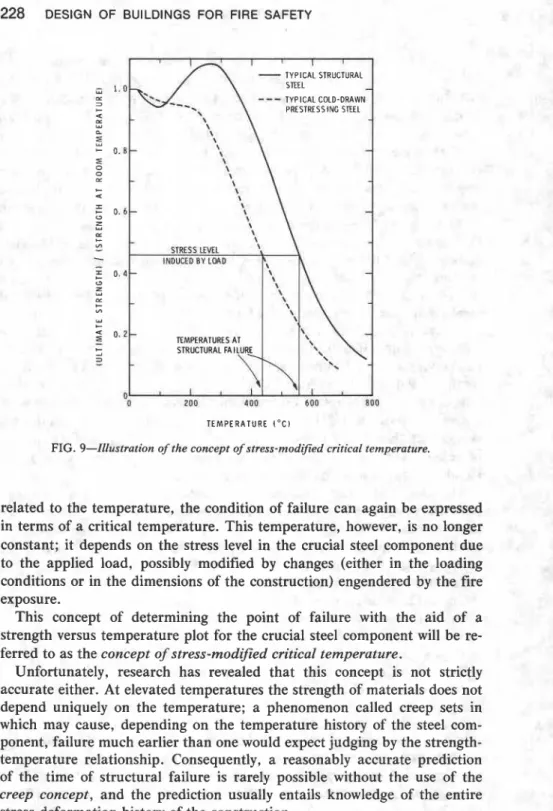
From the point of view of fire resistance, the stress-deformation history of constructions is of no direct interest; it becomes informative only if it provides guidance in the evaluation of the point of structural failure. Ob- servations have shown that for certain types of constructions, namely those whose performance in fire depends on some load-bearing steel components (for example, protected steel structures, reinforced or prestressed concrete beams), the attainment of a critical temperature level by a steel component of decisive importance often signals the imminence of structural failure. Clearly, when dealing with constructions of this type, there is little need to know their stress-deformation histories, as the time of their structural failure is predictable from their temperature histories.
This concept of identifying the point of structural failure with the attain- ment of a critical temperature level at some crucial location is very popular and, as discussed earlier, has been accepted for specifying the failure criteria for certain types of constructions in the standard fire tests. It will
be referred to as the concept of critical temperature in this paper.
Clearly, this concept is based on an oversimplification of the actual con- ditions. Even common sense dictates that the temperature at which the failure is expected to occur cannot be independent of the loading conditions. It is more realistic to assume that structural failure is liable to occur when, as illustrated in Fig. 9, the strength of the load-bearing steel component of decisive importance is reduced, due to heating, to a value equal to the stress induced by the effective load. Naturally, if it is assumed that the reduction of the strength of any particular kind of steel is uniquely