Publisher’s version / Version de l'éditeur:
Vous avez des questions? Nous pouvons vous aider. Pour communiquer directement avec un auteur, consultez la
première page de la revue dans laquelle son article a été publié afin de trouver ses coordonnées. Si vous n’arrivez pas à les repérer, communiquez avec nous à [email protected].
Questions? Contact the NRC Publications Archive team at
[email protected]. If you wish to email the authors directly, please see the first page of the publication for their contact information.
https://publications-cnrc.canada.ca/fra/droits
L’accès à ce site Web et l’utilisation de son contenu sont assujettis aux conditions présentées dans le site LISEZ CES CONDITIONS ATTENTIVEMENT AVANT D’UTILISER CE SITE WEB.
Building Research Note, 1986-04
READ THESE TERMS AND CONDITIONS CAREFULLY BEFORE USING THIS WEBSITE. https://nrc-publications.canada.ca/eng/copyright
NRC Publications Archive Record / Notice des Archives des publications du CNRC :
https://nrc-publications.canada.ca/eng/view/object/?id=6e105e97-955e-4439-9913-e60921130bc6 https://publications-cnrc.canada.ca/fra/voir/objet/?id=6e105e97-955e-4439-9913-e60921130bc6
NRC Publications Archive
Archives des publications du CNRC
This publication could be one of several versions: author’s original, accepted manuscript or the publisher’s version. / La version de cette publication peut être l’une des suivantes : la version prépublication de l’auteur, la version acceptée du manuscrit ou la version de l’éditeur.
For the publisher’s version, please access the DOI link below./ Pour consulter la version de l’éditeur, utilisez le lien DOI ci-dessous.
https://doi.org/10.4224/40000469
Access and use of this website and the material on it are subject to the Terms and Conditions set forth at
Hermetically-sealed glazing: laboratory testing procedures
Ser
TR1
R92
no. 244
c . 2B D G
National
Research
Conseil nationalI*
Council Canadade
recherchesCanada
Institute
for
lnstitutde
Research
in
recherche en
Construction
constructionBuilding
Research Note
Hermetically-Sealed Glazing:
Laboratory Testing Procedures
by R.P. Bowen and
R.G.
Perrault
HERMETICALLY-SEALED GLAZING: LABORATORY
TESTING PROCEDURES
by
R.P.
Bowen and R.G. Perrault
Building Services Section
Institute for Research in Construction
BRN 244
ISSN
0701-5232
Ottawa, April
1986@National Research Council Canada 1986
TABLE
OFCONTENTS
Abstract /%sum6
~ntroduction
General Instruct
ions
Sample Selection and Identification
Initial Seal Test
Initial Dew-Point Temperature Test
UV-Exposure Test
Weather-Cycling Test
High-Humidity Cycling
Summary
Acknowledgements
Sample Record Sheet
Page
1
1
2
3 3 4 6 8 9 1 1 1 1 12HERMETICALLY-SEALED GLAZING: LABORATORY TESTING PROCEDURES
by
R.P. Bowen and R.G. Perrault
ABSTRACT
Until 1986, the Institute for Research in Construction (IRC) ran the
only independent test facility in Canada capable of testing sealed glazing
units to the Canadian standard CAN2-12.8 "Insulating Glass Units". Since
private laboratories have expressed an interest in conducting these tests
for the industry, the laboratory procedures used at IRC have been summarized
in this Note to aid in setting up and operating similar test facilities.
Details on the dew-point determination, initial seal, weather-cycling,
high-humidity cycling, and ultraviolet-exposure tests are given.
Jusqu'en 1986, 1'Institut de recherche en construction (IRC) possedait
la seule installation canadienne permettant de rgaliser des essais
commerciaux sur des panneaux
B
vitres 6tanches pour conformit6
Bla norme
canadienne CAN2-12.8 "Panneaux isolants en verre". Les laboratoires priv6s
stetant
montrgs int6ress6s
B
effectuer ces essais pour l'industrie, 1'IRC a
bien voulu rgsumer B
son intention, dans cette Note, ses mgthodes d'essai en
laboratoire afin d'aider le secteur priv6 B mettre sur pied et 3
exploiter
des installations d'essai semblables.
Ondonne ici des precisions
concernant la dgtermination du point de r o d e ainsi que les essais
dV6tanch6it6
initiale et d'exposition aux cycles dfintemp6ries,
aux cycles
Btaux d'humiditg klev6 et aux rayons ultraviolets.
INTRODUCTION
Sealed glazing units have been widely used in Canada for over twenty
years. When they were first used, there were no standards, and some
products exhibited poor field performance. The test procedures developed by
the Institute for Research in Construction (IRC), National Research Council
of Canada, to assess sealed glazing units form the basis of the present
Canadian standard CAN2-12.8-M76 "Insulating Glass Units", as well as other
standards around the world. Until 1986, DBR ran the only independent test
facility in Canada capable of testing to the standard. Since private
laboratories have expressed interest in conducting these tests, this Note
describes the laboratory procedures used at IRC to assist in setting up
similar facilities.
The standard CAN2-12.8-M76 is a performance-based standard requiring
the assessment of a number of samples submitted by the applicant. Briefly,
the procedures consist of determining the dew point of the air within the
sealed space and assessing for initial seal leaks in 18 of 20 submitted
samples. From the 18 samples,
2 are selected for exposure in an ultraviolet
chamber. Lastly, the final dew point of each of the
12units exposed to the
weather and high-humidity cycles is determined.
An
outline of each test is provided in the following sections. Readers
are, however, referred to the standard in place at time of testing for
details and current revisions.
GENERAL
INSTRUCTIONS
Twenty
355
x 510mm hermetically-sealed glazing units (double or
triple) are received from the manufacturer for tests, in accordance with the
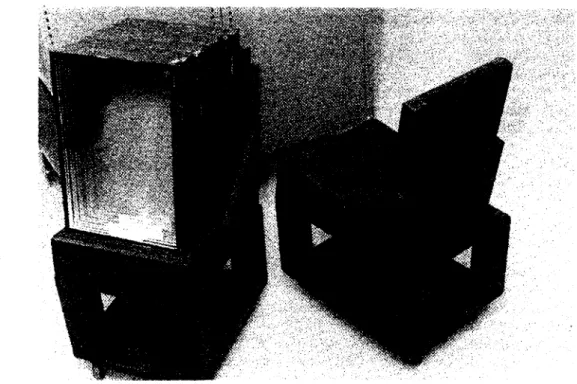
standard. After the units have been individually removed from the shipping
crates and inspected for damage or flaws, they are placed on a window cart
which holds the units in a vertical position (Figure
1).
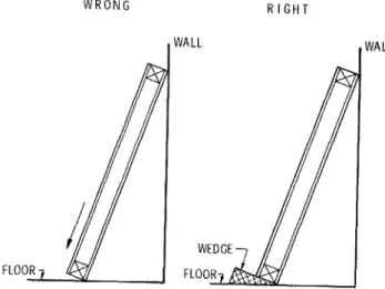
This cart should
be designed so that an equal load on each lite of the unit is maintained, to
prevent any shifting that may occur if the weight of the unit is borne by
one lite only (Figure 2).
The principle of equal support on all lites of a
unit should be observed during all stages of testing and storage.
Figure 1.
Window carts
The temporary edge channels or caps, put on the glazing units for
handling, may be left on while the units are handled in the laboratory.
They should, however, be removed before the units are installed in the
weather-cycling, high-humidity and UV-exposure apparatuses.
To ensure that all the stages of testing are in accordance with the
standard, temperatures are monitored and recorded for each apparatus by
means of a multi-point data recorder.
SAMPLE SELECTION
AND IDENTIFICATION
After selecting at random 18 units in good condition from the set
supplied by the applicant, sequentially number them with a permanent
water-resistant marker. For
W R O N G R I G H T
triple units, the side with the
number is considered as side
1.WALL WALL
Record any information on
attached labels from inspection
agencies, as well as flaws or
damage observed during the
initial inspection. At this
stage, check the test
application and the
cross-section drawings of the
units to ensure that all
required items have been
provided and that the proper
FLOOR 7
units have been received for
testing.
Figure 2.
Sealed unit edge support
INITIAL SEAL TEST
The 18 units are placed, in order of their identification number, in
the seal-leakage vacuum chamber (Figure 3 )
where they are exposed to a
vacuum of 10 kPa for
2$hours. The glass deflection is measured once the
vacuum has been reached, again after 2f hours, and again after the vacuum
has been released. The deflection measurements before and after testing are
compared with the criteria in the standard to determine whether the units
have passed or failed.
To i n s t a l l t h e u n i t s i n t h e chamber, s e p a r a t e t h e two arms h o l d i n g t h e d i a l i n d i c a t o r s w i t h one hand w h i l e s l i d i n g e a c h u n i t i n t o p l a c e w i t h t h e o t h e r . Gently r e l e a s e t h e arms s o t h a t t h e c o n t a c t p i n s l a n d smoothly. A f t e r a l l t h e u n i t s a r e i n p l a c e , a d j u s t t h e d i a l i n d i c a t o r s used t o measure g l a s s d e k e c t i o n s t o t h e same s e t t i n g . The dia3: s e t t i n g , which depends on t h e t h i c k n e s s of t h e u n i t , s h o u l d a l l o w f o r d e f l e c t i o n of a t l e a s t 5 mm i n e i t h e r d i r e c t i o n . Record t h i s s e t t i n g as t h e i n i t i a l r e a d i n g ( s e e Table 1 f o r sample r e c o r d s h e e t ) . Then t a p e t h e a c c e s s p a n e l i n t o p l a c e , and s t a r t t h e vacuum pump. Note t h e s t a r t time. Once t h e low p r e s s u r e h a s been r e a c h e d , n o t e t h e r e a d i n g s on t h e d i a l s and r e c o r d them (column 1 o f r e c o r d s h e e t ) . A f t e r 2) h o u r s , r e a d and r e c o r d t h e d e f l e c t i o n (column 2 ) . Then t u r n o f f t h e vacuum pump and a l l o w t h e chamber t o r e t u r n t o a t m o s p h e r i c p r e s s u r e w i t h o u t removing t h e a c c e s s p a n e l o r opening t h e bleed-off valve. Once t h e chamber i s back t o a t m o s p h e r i c p r e s s u r e , t a k e a f i n a l set of r e a d i n g s and r e c o r d them ( f i n a l ) . L a s t l y , remove t h e u n i t s from t h e chamber.
This t e s t i s conducted a t a l a b o r a t o r y t e m p e r a t u r e of 22OC. A
thermocouple t o monitor l a b o r a t o r y a i r t e m p e r a t u r e i s c e n t r a l l y l o c a t e d i n t h e l a b o r a t o r y , f r e e l y hanging 300 mm from t h e c e i l i n g ,
INITIAL DEW-POINT TEMPERATURE TEST
<
THERMOCOUPLEBRASS PIPE-' BRASS OR G l A S S CYLINDER
160 mrn H I G H x 5 0 m m D I A ( I F THERMOMETER USED, CYLINDER MUST BE GLASS) SUPPORT
FOR PIPE\
<?
[EXTRUDED POLYSTYRENE 130 m m D I A WITH 5 0 m m CENTRE SECTION CUT-OUT
/ \ \
THERMOCOUPLE -/ \THIN BRASS SECTION
(PRESSED CENTRALLY E T H A N O L A PPROX, 0.50 m m
AGAINST THIN THICK x 5 0 m m D I A
BRASS SECTION) F i g u r e 4. Dew-point a p p a r a t u s The dew p o i n t
i s
a c o n d i t i o n t h a t r e l a t e s t o t h e amount of m o i s t u r e i n t h ea i r
of t h e s e a l e d s p a c e . The c o l d e r t h e dew p o i n t , t h e l e s s t h e amount of m o i s t u r e p r e s e n t i n t h e a i r . The dew p o i n t of t h e 18 u n i t s i s determined by u s i n ga
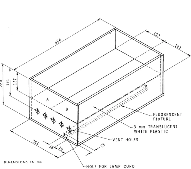
Dew P o i n t Apparatus (DPA) ( F i g u r e 4). By adding d r y i c e and a l c o h o l t o t h e DPA, t h e t e m p e r a t u r e of t h e b r a s s bottom c a n be lowered t o t h e d e s i r e d l e v e l . A l i g h t i n g box ( F i g u r e 5) i s used f o r o b s e r v i n g t h e m o i s t u r e d e p o s i t f o l l o w i n g removal of t h e DPA. To b e g i n t h e t e s t , p l a c e a p p r o x i m a t e l y 75 m l of e t h a n o l i n t o t h e DPA t o g e t h e r w i t h enough dry i c e t o c o o l t h e e t h a n o l t o t h e d e s i r e d t e m p e r a t u r e . P l a c e a u n i t on t h e l i g h t i n g box, which i s p o s i t i o n e d w i t h
D I M E N S I O N S I N m m
\ H O L E F O R L A M P C O R D
N O T E : T O P P O R T I O N ( A B O V E P L A S T I C SHEET) O F B O X I N T E R I O R P A I N T E D F L A T B L A C K . L O W E R I N T E R I O R P O R T I O N P A I N T E D G L O S S Y W H I T E
Figure 5.
Light box for dew-point test
the translucent plastic side closest to the operator. (If two DPAs are
available, two units can be placed on the box at once.)
Apply a thin film
of alcohol to the face of the unit directly above the lighted portion of the
box and rest the DPA against the unit for
3minutes. Note the amount of
deposit immediately after removing the DPA. The surface will have to be
wiped with a small brush or cloth wetted with alcohol to remove outer
surface condensation and facilitate viewing the deposit. The black portion
of the viewing box can be used as a background for making the observation.
Determining a dew point close to the passlfail criteria may require
several attempts. Test first at the coldest state possible. If no frost or
moisture deposit occurs, record it as such (NF).
If there is a deposit,
raise the temperature of the DPA and repeat the procedure. Before
determining a second dew point, reheat the glass to near room temperature.
This reheating can be made easier by placing
aflat piece of metal
t h e a r e a of t h e DPA. To r e d u c e t h e p o s s i b i l i t y of a n e r r o n e o u s r e a d i n g , l o c a t e t h e n e x t dew p o i n t a t l e a s t 175 mm away from t h e p r e v i o u s one.
I d e a l l y , when t h e dew p o i n t t e m p e r a t u r e i s r e a c h e d , o n l y f a i n t c o n d e n s a t i o n s h o u l d be b i s i b l e .
-7
The d e v i c e t o measure t h e t e m p e r a t u r e of t h e d r y i c e and e t h a n o l s o l u t i o n s h o u l d be r e c a l i b r a t e d a n n u a l l y a t a r e l i a b l e p h y s i c s c a l i b r a t i o n c e n t r e .
A f t e r t h e i n i t i a l dew p o i n t h a s been d e t e r m i n e d , u n i t s a r e s e l e c t e d f o r t h e UV-exposure, w e a t h e r - c y c l i n g and high-humidity-cycling tests.
UV-EXPOSURE TEST
Two of t h e e i g h t e e n u n i t s a r e exposed t o UV r a d i a t i o n and h e a t i n a UV-exposure box ( F i g u r e 6 ) . The a i r i n t h e box i s m a i n t a i n e d a t
60°C.
A
c o l d p l a t e , m a i n t a i n e d a t22OC,
i s mounted on t h e u p p e r l i t e of e a c h t e s t u n i t . During t h e t e s t , o r g a n i c vapours a r e d r i v e n from t h e s e a l a n t and any o t h e r component p a r t s by t h e h i g h t e m p e r a t u r e andU V
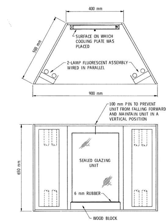
exposure. Thesev a p o u r s , i f n o t a b s o r b e d by t h e d e s i c c a n t i n t h e u n i t , a r e condensed on t h e s u r f a c e of t h e g l a s s by t h e c o l d p l a t e . Following a 7 d a y e x p o s u r e , e a c h u n i t i s p l a c e d i n a viewing box ( F i g u r e
7 )
and observed f o r e v i d e n c e of a d e p o s i t on t h e i n s i d e s u r f a c e of t h e g l a s s l i t e a d j a c e n t t o t h e c o l d p l a t e . D I A L THERMOMETER OR THERMOCOUPLE COOLING WATER TEMPERATURE DETERMINED A T --WATER INPUT COOLING PLATES AUTO TRANSFORMER TO ADJUST VOLTAGE F i g u r e 6 . U l t r a v i o l e t e x p o s u r e boxLSURFACE ON WHICH COOLING PLATE WAS PLACED
2-LAMP FLUORESCENT ASSEMBLY WIRED I N PARALLEL
WOOD BLOCK
NOTE: PAINT INTERIOR OF BOX MATTE BLACK
Figure
7.
Viewing box for ultraviolet exposure test
The UV-exposure box is made of plywood and lined with aluminum foil.
The UV and heat source is a
G.E. Sunlamp (RS275W) mounted in the bottom of
the box and powered through a variac. The two test units are placed in the
box and supported at an angle of about 45O above the lamp. The cold plates
are supplied with a mixture of hot and cold water to maintain a temperature
of 22OC. The lid of the box contains a 30
mm x60 mm adjustment hole which
can be progressively uncovered to make fine adjustments to the air
To b e g i n t h e p r o c e d u r e , s e l e c t 2 u n i t s from t h e s e t of 18. Clean t h e u n i t s on both f a c e s w i t h g l a s s c l e a n e r and i n s t a l l them i n t h e UV-exposure box. Then p l a c e t h e c o l d p l a t e on t h e u p p e r l i t e of e a c h u n i t . The c o l d p l a t e m u s t i r e s t f l a t l y on t h e c e n t r e of t h e u n i t , and a l l l i t e s of t h e u n i t s h o u l d rest. e q u a l l y on t h e s u p p o r t s . Turn on t h e l a m p and a d j u s t t h e v a r i a c t o p r o v i d e t h e s p e c i f i e d UV i n t e n s i t y and approximate t e m p e r a t u r e . F i n e t e m p e r a t u r e a d j u s t m e n t s c a n b e made by changing t h e a r e a of t h e h o l e i n t h e l i d . Once t h e t e m p e r a t u r e h a s been r e a c h e d , measure t h e UV i n t e n s i t y w i t h a UV-intensity meter t h r o u g h t h e opening i n t h e l i d t o e n s u r e t h a t i t complies w i t h t h e s t a n d a r d . A d j u s t t h e t e m p e r a t u r e of t h e w a t e r r u n n i n g t h r o u g h t h e c o l d p l a t e s t o m a i n t a i n 22OC t h r o u g h o u t t h e t e s t .
A f t e r t h e two u n i t s have been exposed f o r
7
d a y s , s w i t c h o f f t h e U V lamp and remove t h e u n i t s once t h e y a r e c o o l enough t o handle. Immediately f o l l o w i n g removal, c l e a n e a c h u n i t w i t h g l a s s c l e a n e r and p l a c e i t i n t h e viewing box, i n s u c h a way t h a t i t can be viewed t h r o u g h t h e s u r f a c e on which t h e c o l d p l a t e was p l a c e d d u r i n g t h e test. Darken t h e room t o e l i m i n a t e any g l a r e on t h e u n i t , and t u r n on t h e viewing lamps. S t a n d i n g about 2 m d i r e c t l y i n f r o n t of t h e u n i t w i t h a n e y e l e v e l a t mid-height of t h e u n i t , o b s e r v e i t f o r any e v i d e n c e of a d e p o s i t . o n t h e i n t e r i o r g l a s s s u r f a c e . F i g u r e 8. Weathering a p p a r a t u s f o r i n s u l a t i n g g l a s s u n i t s I f one u n i t h a s a d e p o s i t , two a d d i t i o n a l u n i t s a r e t e s t e d . S i n c e t h e t e s t i s n o t i n t e n d e d t o a s s e s s g l a s s b r e a k a g e , u n i t s broken d u r i n g t h e t e s t a r e r e p l a c e d and t h e t e s t i s r e p e a t e d . Temperature i s m o n i t o r e d by a thermocouple suspended from a f i n e w i r e 300 mm above t h e c e n t r e of t h e sunlamp t o s e n s e i n s i d e a i r t e m p e r a t u r e , and a second thermocouple t a p e d t o t h e w a t e r o u t l e t of t h e c o l d p l a t e t o s e n s e t h e t e m p e r a t u r e of t h e c o o l i n g w a t e r a s i t g o e s t o d r a i n . WEATHER-CYCLING TEST I n t h e w e a t h e r - c y c l i n g t e s t , f o u r u n i t s are exposed t o l a b o r a t o r y a i r on one s i d e and t o a p p a r a t u s chamber a i r on t h e o t h e r s i d e ( F i g u r e 8). The chamber a i r i s c y c l e d from -32OC t o 52OC i n a 4-hour c y c l e ( F i g u r e 9). On t h e cool-down c y c l e , w a t e r i s s p r a y e d on t h e u n i t s f o r 5 minutes. Exceptr I ! I I I I A I R CIRCULATION 115 m i n 120 m i n
-
-
I * 90 m i nHlATlNG
5 m i n-ti--
WATER SUPPLY 60 m i nONE CYCLE COOL1 NG
*
-
--
-
-
I I I I
air is circulated in the chamber on
a continuous basis. The units are
exposed to 320 cycles after which
their final dew points are
determieed.
Select 4 units from the set of 18
for this test and remove any excess
dirt or foreign deposits. Measure
the thickness of each unit using a
6 0
depth gauge; then adjust the stops
on the sample support frame so that
4 0
U
when each unit is installed, the
surface exposed to the laboratory is
2 0
flush with the exterior surface of
3
I-
the frame. Once all four openings
4
~i
in the frame have been adjusted,
w 0
a
install the units and hold them in
H
W
+
place while covering the gaps
- 2 0
between frame and unit with plastic
film tape (suitable for temperature
- 4 0
ranges of -40 to 60°C).
As
a safety
0 6 0 1 2 0 1 8 0 2 4 0
precaution, start by installing the
TIME, min
lowest unit and work up to the top
of the frame. To reduce water
Figure 9.
Weather-cycling test cycle
leaks, check that all of the tape is
firmly pressed flat onto the support
frame, the unit, and onto itself in
overlapping corners. Then place extruded polystyrene (25 mm
x100 mm) over
the unit edges as shown in Figure 8.
Monitor the windows closely for the first 50 cycles
(83
days).
In the
event of glass breakage, replace the unit and continue the cycling (a
maximum of three breaks between exposures to the weathering apparatus and
t h ~
high-humidity chamber is permitted by the CAN2-12.8-M76 standard).
On
completion of 320 cycles (533 days), remove the units from the apparatus and
condition them in the laboratory air for one week. m e n determine their
final dew points as previously described.
The best time to remove the units is after the water spray portion of
the cycle since, at that point, the units and the apparatus are near room
temperature. New units should also be installed then to enable proper
adhesion of the plastic film tape to the support frame.
Six thermocouples are used to monitor temperatures in the laboratory
weathering apparatus; three located opposite the top units and three
opposite the bottom units. Each thermocouple is centrally positioned
between the two upper cooling coils for the unit.
HIGH-HUMIDITY CYCLING
In the high-humidity test, eight units are exposed to moist air in an
enclosed cabinet (Figure 10).
The air within the cabinet is kept at or near
saturation by continuous water spraying; the temperature of the spray water
r SLIPPORT TO M A I N T A I N
SEALED GLAZl NG UNITS
?,
n
i
GERTICAL
POSITION OF U N I T S ?> HEATER VOLT WATER A I R CIRCULATION'
COOLING C O I L F i g u r eLO.
High-humidity c y c l i n g c a b i n e t 1 I I I I I I i s a d j u s t e d t o c y c l e t h e a i r-
HEATING 90 t e m p e r a t u r e i n t h e c a b i n e t from 22OC t o 55OC i n a 3-hour c y c l e( F i g u r e 1 1 ) The t e m p e r a t u r e i n t h e
a
c a b i n e t i s monitored by one $' COOLING thermocouple l o c a t e d i n t h e c a b i n e t * 6 0 - - a i r . The u n i t s a r e exposed t o 224 c y c l e s a f t e r which t h e i r f i n a l dew p o i n t s a r e determined. S e l e c t 8 u n i t s from t h e s e t of 18 f o r t h i s t e s t and c l e a n them. I n s t a l l t h e u n i t s v e r t i c a l l y i n t h e c a b i n e t u s i n g p o s i t i o n i n g p i n s o r s p a c e r s . A s p a c e between e a c h u n i t should be provided t o a l l o w a i r t o c i r c u l a t e . I I I Monitor t h e u n i t s c l o s e l y f o r t h e l o o I I I I 6 0 1 2 0 1 8 0 2 4 0 f i r s t 50 c y c l e s(64
d a y s ) . I f a T I M E , m i n u n i t b r e a k s , r e p l a c e i t and c o n t i n u e F i g u r e 11. High-humidity t e s t c y c l e c y c l i n g . On completion of 224 c y c l e s (28 d a y s ) , remove t h e u n i t s from t h e c a b i n e t and c o n d i t i o n them i n t h e l a b o r a t o r y a i r f o r one week. Then d e t e r m i n e t h e i r f i n a l dew p o i n t s a s p r e v i o u s l y d e s c r i b e d .The easiest time to inspect the units is when the high-humidity cabinet
is turned off during the hot portion of the cycle and the lid is opened for
a short time to allow the units to dry off.
To reduce particulates which could block tRe water-spray nozzle, the
water in the high-humidity cabinet should be changed every 3 months. Care
should be taken to ensure that the water level is maintained below the
bottom of the units. This can be done by using a water reservoir and float
system.
SUMMARY
The procedures discussed above have evolved over a number of years.
They are intended to reduce handling and accidental breakage of samples.
Because the dew-point determination and the UV-exposure test have subjective
components which are operator-dependent, laboratory procedures must be
established and rigorously followed to ensure consistency from one test to
another. Actual details of the procedures may change as the standard is
modified; nevertheless, the basic approach should remain similar. Due to
the nature of the equipment and the test cycles, the temperature of all
apparatuses should be monitored continuously to ensure compliance to the
standard.
ACKNOWLEDGEMENTS
The authors wish to acknowledge the dedicated work of
K.R. Solvason and
H.
Egan, on which these procedures were based.
*Units 1-18 undergo i n i t i a l s e a l and i n i t i a l dew p o i n t t e s t s . U n i t s 1-4 undergo weather c y c l i n g .
U n i t s 5-12 undergo h i g h - h ~ l m i d i t y c y c l i n g . U n i t s 17,18 undergo UV-exposure t e s t .