Classical and fluctuation-induced electromagnetic
interactions in micron-scale systems: designer
bonding, antibonding, and Casimir forces
The MIT Faculty has made this article openly available.
Please share
how this access benefits you. Your story matters.
Citation
Rodriguez, Alejandro W., Pui-Chuen Hui, David P. Woolf, Steven
G. Johnson, Marko Lončar, and Federico Capasso. “Classical and
Fluctuation-Induced Electromagnetic Interactions in Micron-Scale
Systems: Designer Bonding, Antibonding, and Casimir Forces.”
Annalen Der Physik 527, no. 1–2 (November 6, 2014): 45–80.
As Published
http://dx.doi.org/10.1002/andp.201400160
Publisher
John Wiley & Sons
Version
Author's final manuscript
Citable link
http://hdl.handle.net/1721.1/105104
Terms of Use
Creative Commons Attribution-Noncommercial-Share Alike
Classical and fluctuation-induced electromagnetic interactions in micronscale systems:
designer bonding, antibonding, and Casimir forces
Alejandro W. Rodriguez,1, ∗ Pui-Chuen Hui,2 David N. Woolf,2
Steven G. Johnson,3 Marko Loncar,2 and Federico Capasso2
1Department of Electrical Engineering, Princeton University, Princeton, NJ 08540 2
School of Engineering and Applied Sciences, Harvard University, Cambridge, MA 02138
3Department of Mathematics, Massachusetts Institute of Technology, Cambridge, MA 02139
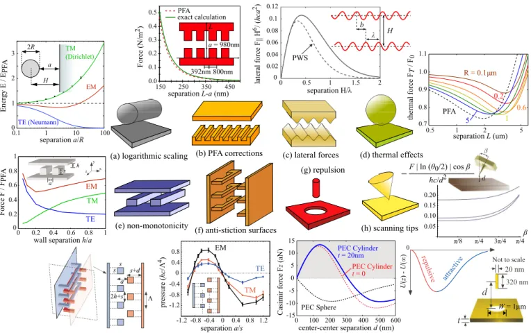
Whether intentionally introduced to exert control over particles and macroscopic objects, such as for trapping or cooling, or whether arising from the quantum and thermal fluctuations of charges in otherwise neutral bodies, leading to unwanted stiction between nearby mechanical parts, electromag-netic interactions play a fundamental role in many naturally occurring processes and technologies. In this review, we survey recent progress in the understanding and experimental observation of optomechanical and quantum-fluctuation forces. Although both of these effects arise from exchange of electromagnetic momentum, their dramatically different origins, involving either real or virtual photons, lead to different physical manifestations and design principles. Specifically, we describe recent predictions and measurements of attractive and repulsive optomechanical forces, based on the bonding and antibonding interactions of evanescent waves, as well as predictions of modified and even repulsive Casimir forces between nanostructured bodies. Finally, we discuss the potential impact and interplay of these forces in emerging experimental regimes of micromechanical devices.
I. INTRODUCTION
Light can exert a force. Although this statement is uncontroversial today, its confirmation was a remarkable triumph a little over a century ago[1], only a couple of centuries after scientists had finally managed to show that light moves at all (as opposed to appearing instan-taneously). Much of the early treatment of this force was limited to light incident on planar surfaces described by some absorption and reflection coefficients, in which the resulting “radiation pressure” can be explained by intuitive arguments that continue to dominate pedagog-ical materials. Perversely, this classpedagog-ical force is easiest to understand through a quantum picture [2]: since a photon with energy U has relativistic momentum U/c, a black surface that completely absorbs normal-incident light with power P should experience a force P/c, cor-responding to the rate at which it receives momentum. Similar arguments apparently imply, from conservation of momentum, that light can only “push” on a flat sur-face (with a force of at most 2P/c) and can never “pull.” However, in microstructured systems, the forces in-duced by electromagnetic waves are complicated by a
number of additional possibilities. One can consider
forces induced by guided waves, resonant modes, and evanescent waves in addition to forces exerted by inci-dent waves from vacuum, which can both change the na-ture of the force and (thanks to spatiotemporal localiza-tion) greatly enhance its strength. In systems with mul-tiple components, one component can either pull or push a neighboring component, since momentum-conservation restrictions only apply to the net force on all components
∗corresponding author: arod@princeton.edu; corresponding
au-thor.
rather than to the force on any individual object. Even for an isolated object, focused beams on a small object can scatter oblique light forward, a transfer of momen-tum from the object to the wave that creates an optical “tractor beam” [3]. We review many of these possibilities and their applications in Section II.
In addition to these geometric and localization effects, Section III reviews another consideration that arises for optical forces at submicron scales: classical optical forces arise from external sources of electromagnetic fields, but there are also internal sources, namely thermal and quan-tum charge oscillations. Most famously, the vibrations of matter give rise to thermal radiation, the familiar glow of hot objects [4], but the same fields carry momentum as well as energy. Intuitively, two hot objects will push each other apart with their thermal radiation, but this picture is incomplete because it does not include ambient radiation, and the effect is dramatically altered for ob-jects in thermal equilibrium with their environment. For well-separated objects in thermal equilibrium, the om-nidirectional radiation from both the objects and their environment exactly cancels and there is no net force on any object, but for surfaces at submicron separations the evanescent coupling and other effects tend to produce an attractive force. In the limit of zero temperature, this at-tractive force remains due to quantum fluctuations and is known as a “Casimir” force [5]. For a single pair of atoms, the same phenomenon is a van der Waals force known as the “London-dispersion” force’ (or the “Casimir–Polder” force once wave effects are included) [6]. (Although such forces have a sometimes bewildering variety of theoret-ical descriptions, ranging from zero-point energy sums to path-integral models, it turns out that all of these expressions are mathematically equivalent to the forces of fields produced by vibrating charges in matter [7].) Casimir forces between parallel metallic surfaces, first predicted in 1948 and reviewed in Section III B 2, were
finally observed quantitatively in 1978 [8] and have sub-sequently been measured in a wide variety of microelec-tromechanical systems (MEMS) with increasing preci-sion [9]. However, until the last decade, both theoret-ical predictions and experiments were limited to planar or near-planar geometries with the exception of a hand-ful of theoretical special cases. This has now changed, thanks to both powerful new computational tools and rapidly expanding capabilities of micromechanical exper-iments, enabling an explosion in designer Casimir forces (reviewed in Section III B) with exotic properties extend-ing far beyond simple attraction between parallel sur-faces. Because Casimir forces remain when all other elec-tromagnetic interactions (external fields, static charges, and so on) are removed, Section III C explains that they represent both an ultimate limitation and, potentially, an opportunity for MEMS devices as they approach the nanoscale.
II. CLASSICAL OPTICAL FORCES
Researchers have long pursued the use of electromag-netic waves to induce mechanical motion. Kepler was the first to hypothesize that solar radiation is responsi-ble for the deflection of comet tails away from the sun. By 1903, Lebedew [10] and Nichols and Hull [11] had proved Maxwell’s hypothesis that light impinging on a thin metallic disk in vacuum would induce measurable motion. Over the course of the next century, applica-tions for harnessing the energy of light were seen in sys-tems ranging from “Solar Sails” and accelerators [12] to optical traps and tweezers [3, 13–15]. In the last decade, interest in near-field optical interactions has steadily in-creased, as on-chip optical circuitry has presented vi-able alternatives to slower electronic systems. The initial single-beam trapping experiment by Ashkin et. al. [3] was the first to demonstrate the usefulness of optical gradient forces for the manipulation of macroscopic ob-jects: a tightly focused laser beam can trap a spherical dielectric particle in both normal and tangential direc-tions by balancing the scattering and gradients forces acting on the particle. Subsequent experiments demon-strated laser cooling and trapping of ions and neutral atoms [16–19], leading to breakthroughs in various as-pects of atomic physics, including the realization of Bose-Einstein condensates [20, 21], quantum simulation of ar-rays of atoms trapped in optical lattices, and a new field of atom optics [22]. The physics of optomechan-ics has a strong resemblance with Doppler cooling in atomic/optical physics [23–25], whose groundbreaking development preceded optomechanics by two decades, ex-cept that in optomechanical systems the predicted quan-tum nature is manifested in macroscopic objects. Instead of the atomic energy levels being dressed due to strong light–atom interactions, in optomechanics, the photonic resonant states are dressed due to strong optomechan-ical interactions. In addition to dynamoptomechan-ical effects,
op-tomechanical forces also lead to nano- and micro-meter mechanical displacements with milliwatts or smaller in-cident powers. Similar to conventional optical trapping, optical forces in optomechanical systems can be catego-rized into radiation, gradient, or photothermal forces. In the following sections, we briefly review the basic physics of gradient optical forces in micronscale systems and survey recent developments paving the way toward des-ignable interactions in a wide range of optomechanical systems, where the amplitude, wavelength, and phase of incident light can be used to obtain tunable attractive and repulsive forces.
A. Radiation, gradient, and photothermal forces
Radiation pressure involves transfer of momentum via propagating waves to a compliant object. While a pho-ton carrying momentum ~ω/c, or alternatively incident light carrying power P , is bounded by momentum con-servation to contribute net pressure ≤ 2P/c (assuming 100% of the light is reflected from the object), the small momentum imparted by the photon can be drastically
enhanced by introducing an optical cavity. Assuming
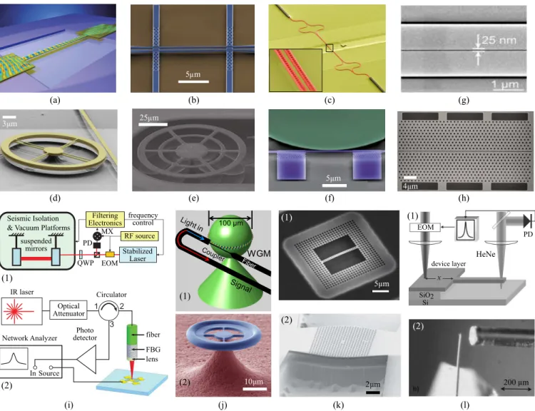
negligible lossses, the force on any individual part of a cavity can be many times larger than the net force on the cavity as the photon continues to exchange momen-tum with it over the cavity lifetime τ , thereby enhanc-ing the force by a factor of τ . The canonical example of such radiation-pressure enhancements in optomechan-ical systems is a simple Fabry-Perot cavity formed by two highly reflective mirrors in which one of the mir-rors is allowed to move, leading to a number of ob-servable mechanical effects [44]. Demonstrations of ra-diation pressure enhancement based on this principle cover a wide spectrum of length scales and designs, from large-scale mirrors and Fabry-Perot cavities formed by highly reflective Bragg gratings [Fig. 1(i)] to micron-scale whispering gallery modes [Fig. 1(j)] of microring resonators [45], where light circulates along the circum-ference of the cavities. The increasing demand for com-pact systems with smaller features has led to designs with increasing complexity and functionalities, including omnidirectional photonic-crystal (PhC) waveguides op-erating near band edges leading to slow group-velocity modes [46], PhC membranes with ultra-large mechanical lifetimes [47], parallel metallic-plate systems operating in the microwave regime [48], electrostrictive forces arising from strain-dependent refractive index changes [49], and even situations involving exotic materials such as left-handed materials [50] and gain media where the force can pull instead of push objects [51]. Designs tailored for ap-plications in optomechanical systems often involve struc-tures with co-localized optical and mechanical modes [Fig. 1(k)], where the combination of large optical qual-ity factors Q (dimensionless lifetimes in the range of tens of thousands or above) and long-lived mechanical modes (with frequencies in the MHz-GHz) have enabled
excit-(c) (b) (a) (g) (h) (f) (e) (d) 5 m (i) (j) (k) (l) 100 µm WGM 3 m 4 m 10 m 5 m (1) (2) (1) (2) (1) (2) (1) (2) IR laser Network Analyzer Optical Attenuator Photo detector In Source Circulator fiber FBG lens Seismic Isolation
& Vacuum Platforms suspended mirrors frequency control Filtering Electronics RF source Stabilized Laser EOM QWP PD MX HeNe EOM PD device layer SiO2 Si 25 m 2 m 200 m 5 m
FIG. 1. Selected optomechanical structures actuated by radiation, gradient, and photothermal forces. Gradient-based designs include: (a) A silicon waveguide acting as a doubly-clamped beam coupling light incident from the underlying buried oxide layer, exhibiting attractive, lateral gradient forces and Duffing nonlinearities [26]. (b) Coupled silicon waveguides where attractive and repulsive optical forces are exerted by controlling the relative phase of incoming light via a Mach-Zehnder interferometer [27]. (c) Coupled silicon PhC nanobeam cavities where attractive optical forces are observed in the presence of incident incoherent light under atmospheric conditions [28]. (d) Coupled silicon-nitride ring resonators and silica microdisks supporting whispering gallery modes leading to attractive and repulsive forces [29–31]. (f) Dispersive and dissipative reactive forces realized in a system of silicon waveguides coupled to a silicon microdisk [32]. (g) Gold-coated silicon nitride plasmonic waveguides [33] and (h) silicon PhC slot-waveguides [34] exhibiting tightly confined electric fields inside the small air gaps. Radiation-based designs include: (i-1) Fabry–Perot cavities formed by large, kg-scale mirrors suspended by pedulums operating at very high powers and exhibiting optical instabilities [35]. (i-2) High-finesse Fabry-Perot cavities formed by gold-palladium rectangular mirrors [36]. (j-1) Silica microspheres supporting optical and acoustical whispering gallery modes where excitation of mechanical modes is facilitated by stimulated Brillouin scattering [37, 38]. (j-2) Silica microtoroids supporting whispering gallery modes used to demonstrate coherent quantum coupling [39]. (k-1) Silicon optomechanical crystals with phononic shields that have been optomechanically cooled to the quantum ground state [40]. (k-2) InP photonic crystal cavities designed to have strong localization of both optical and mechanical modes [41]. Photothermal-based designs include: (l-1) Silicon cantilevers actuated by thermal stress induced by absorption of visible HeNe light [42]. Here, the photothermal effect is modulated by a Fabry-Perot cavity formed by the silicon cantilever and the bottom silicon substrate. (l-2) Combination of radiation pressure and photothermal effects manifested in an optomechanical system comprised of an optical fiber above a reflective gold-coated silicon cantilever [43].
ing and novel demonstrations of optical spring effects, optomechanically induced self-oscillations, on-chip stor-age and manipulation of light pulses [52] and noise [53],
on-chip accelerometers [54], microfluidic sensors [55], and cooling of macroscopic objects [23, 25, 56–61].
inci-dent evanescent or gradient electromagnetic fields. In op-tomechanical systems, the most explored of these interac-tions is the force induced on a microcavity by the evanes-cent field of a nearby waveguide or substrate, where sim-ilar to radiation pressure, the forces are also greatly en-hanced by resonances [62]. These include microcavities coupled to waveguides [59, 63], free-standing slot waveg-uides leading to wideband tuning and low-power optical modulation [64–66], PhC nanobeam waveguides coupled to substrates leading to unusual, non-monotonic attrac-tive forces [67], zipper-like structures leading to optically controlled mechanical transparency [68–71], hybrid plas-monic waveguides leading to deep subwavelength confine-ment of light [72, 73], and plasmonic nanobeams [33, 74] or bowtie antennas [75], some of which are illustrated in Fig. 1. Tunable optomechanical interactions enabled by large gradient forces [62, 76, 77] are currently be-ing explored in applications rangbe-ing from optical cool-ing [31], optical buffers [34], re-configurable filters [28], non-interferometric signal transduction [70, 78], and op-tical actuators and switches [79–82]. The interaction be-tween coupled resonances through their evanescent field can lead to even richer phenomena, such as tunable at-tractive (bonding) and repulsive (anti-bonding) gradient forces between nearby optomechanical objects. The abil-ity to generate repulsive forces and to tune the sign and magnitude of these interactions by adjusting either the wavelength or phase of incident light is also poised to make an impact in future photonic switching [83] and MEMS devices, where they could be exploited in con-junction with other forces such as Casimir or electrostatic forces (as described in Section III C).
Finally, light can lead to mechanical deformations through photothermal interactions, whereby a movable structure absorbs part of the incident light that is con-verted to heat. For instance, thermal stresses can arise in suspended devices as a result of the difference in thermal expansion coefficients between the device layer and un-derlying supporting substrate[84], leading to bending of the movable structure. Such photothermal deformations can often be enhanced by the introduction of a micro-cavity. Examples illustrated in Fig. 1(l) include a gold-coated silicon cantilever excited by a gold-gold-coated optical fiber placed in close proximity, forming a Fabry–Perot cavity [43], and a cavity formed by a cantilever and neigh-boring substrate, excited with a laser frequency above the silicon bandgap [42]. While the photothermal effect also allows for optical spring tuning and dynamic back-action (mediated by delay due to its finite thermal time con-stant), the photothermal effect often presents itself as a competing effect in the demonstration of several optome-chanical devices [36, 43, 85–89].
B. Designer bonding and antibonding forces
Among the successes of optomechanics is unprece-dented access to quantum regimes of macroscopic
ob-(a) (b)
s/a = 1.0 s/a = 0.1 s/a =
waveguide separation s/a
optical f orce (F/ L) ( ac / P ) wavevector ka/2 frequency ω a/ c -1.5 -1 -0.5 0 0.5 0 0.2 0.4 0.6 0.8 1 attractive repulsive s a 0 0.1 0.2 0.3 0.4 0.5 0.05 0.15 0.25 0.1 0.2 0
FIG. 2. Working principles behind gradient forces in coupled optomechanical systems. (a) Dispersion diagram for a system involving two identical, co-planar square waveguides at var-ious separations s/a = ∞ (black solid), 1 (red dashed) and 0.1 (blue dashed), where a denotes the waveguide width [91]. Insets show the Eyelectric-field profile of both bonding
(sym-metric) and anti-bonding (anti-sym(sym-metric) modes. As s de-creases, the bonding and antibonding mode-frequencies expe-rience red and blue shifts, respectively. (b) Normalized gradi-ent force per unit length and per incidgradi-ent power for the same system, as a function of s (for a fixed incident wavevector), where +/− corresponds to repulsive/attractive forces [92]. In-sets show the in-plate electric-field vectorial distribution and total intensity of both bonding and antibonding modes. The force amplitude of the bonding mode increases monotonically with decreasing s, whereas the anti-bonding force is only re-pulsive at separations s/a & 0.03, becoming attractive at short distances.
jects, most commonly realized in singly resonant optome-chanical structures [39, 40, 90]. Other endeavors for ex-panding the optomechanical toolbox are noteworthy as well. In the next few sections, we present a number of re-cent theoretical and experimental studies which highlight the breadth of designs and functionalities in coupled, res-onant optomechanical systems subject to bonding and antibonding forces.
1. Theory
To illustrate the origin of optical gradient forces be-tween resonant optomechanical systems we begin by con-sidering one of the first proposed optomechanical struc-tures exhibiting this effect, involving two square dielec-tric waveguides placed in close proximity [91]. In such a system, the mutual interaction of degenerate resonances or guided modes via their evanescent fields can induce a splitting of the modes into pairs characterized by attrac-tive and repulsive mechanical forces, analogous to the well-known bonding and anti-bonding states formed by the level splitting (avoided crossings) of interacting de-generate states in quantum systems [93]. The degree of mode splitting from the initial mode frequencies is con-trolled by the coupling strength (or proximity) between the waveguides [91, 94]. The idea is illustrated in the
dis-persion diagram of Fig. 2(a), which shows changes in the frequency dispersion of the two waveguide modes as they approach one another from infinity [91]. The relation-ship between changes in the frequency and mechanical energy of the system can in turn be understood from a simple heuristic quantum-mechanical argument [91]. In particular, assuming that N photons of frequency ω and conserved wavevector are coupled into the waveguide sys-tem, the photonic energy U can be written as,
U = N ~ω, (1)
from which it follows that a small change in the separa-tion will shift ω and result in an optomechanical force,
Fom= − ∂U ∂d = − ∂(N ~ω) ∂d = − U ω ∂ω ∂d (2)
acting on both waveguides. As expected, the final expres-sion for the force does not depend on ~ but rather on the total stored energy in the system and can be derived and verified via classical arguments [95–97]. A useful figure of merit present in Eq. 2 is the so-called optomechanical coupling gom = ∂ω∂d, which fascilitates direct comparison of optomechanical forces between different structures.
Mixing between the modes of the isolated waveguides as they come together causes a splitting in the frequency, where as expected from a simple tight-binding picture or from perturbation theory [93], they hybridize into sym-metric (lower frequency) and anti-symsym-metric (higher fre-quency) modes. Typically, when the guided waves are in phase (a bonding/symmetric mode), the electromagnetic energy can be reduced by increasing the field intensity in high-dielectric regions, leading to an attractive optical force that pushes the waveguides closer to one another. Conversely, when the guided waves are out of phase (an anti-bonding/anti-symmetric mode), the energy can be reduced by increasing the field intensity in low-dielectric regions, leading to a repulsive force. When mechanical degrees of freedom are introduced in these coupled struc-tures, i.e. the waveguides are partially released from the bottom substrate, these optical forces push the waveg-uides in an effort to reconfigure the wavegwaveg-uides and hence lower the total energy. In this particular example, the polarity of the optical force is predominantly determined by the relative phases of the electric field in the respec-tive waveguides, which yields a control parameter to ob-tain tunable optomechanical effects, even switching the sign of the force from attractive to repulsive, an effect that was first observed experimentally in Refs. [27, 98]. Although the simple tight-binding picture above is suf-ficient to explain the main features of gradient forces at large separations d λp, where λp is a characteristic lengthscale corresponding to the exponential tail of the modes, at shorter separations d . λp it can fail dramat-ically and one must therefore rely on exact calculations. These features are illustrated in Fig. 2(b), which shows the forces induced by both the bonding and antibond-ing modes of the waveguides over a wide range of sep-arations. As observed from Fig. 2(b), the force scales
exponentially with d at large separations and exhibits a more complicated d-dependence at smaller separations. In this geometry, non-perturbative effects arising at short separations lead to a dramatic qualitative change in the behavior of the anti-symmetric mode, manifested as an increasingly weaker force with decreasing d which ulti-mately switches sign (becoming attractive) below some threshold d . 0.3a.
Generalizations of this phenomenon to other coupled-cavity systems (e.g. microsphere, microdisk, and pho-tonic crystal cavities) have paved the way for designable gradient forces. While most optomechanical structures often involve some kind of resonant effect, technically Eq. 2 is only applicable in closed systems comprising
lossless (guided) resonances. In the presence of small
losses, e.g. stemming from either radiation or absorp-tion, similar formulas can be derived (independent of the quantum-mechanical picture above) which relate forces to the frequencies, incident power, and lifetimes of the corresponding leaky modes [63, 95, 97]. In more general circumstances where there may not be well-defined reso-nant modes with negligible loss, or situations where there are superpositions of resonant modes with other waves (e.g. light from an external source), modal approaches become problematic. However, because optical forces are directly related to the solution of scattering problems, i.e. electromagnetic fields due to incident currents or fields, one can also frame the calculation of forces using formu-lations that do not rely on either mode or energy calcula-tions and which generalize to other situacalcula-tions of interest,
e.g. non-resonant or broad-bandwidth excitation, and
even optical torques [14]. One such approach involves computing the force via the integral ~F =H h ~T i · d ~S of the time-averaged Maxwell stress-tensor,
Tij = 1 2< " ε0 EiEj− 1 2 X k |Ek|2 ! +µ0 HiHj− 1 2 X k |Hk|2 !# (3)
around some surface S lying in vacuum [2].
Calcula-tion of stress tensors between vacuum-separated bodies sidestep issues relating to evaluation of energy densities
in lossy media 1, and have been performed in a
vari-ety of contexts. For instance, h ~T i can be directly com-puted via eigenmode calculations in systems with neg-ligible loss [100, 101], or more generally by solving a set of linear equations for the fields in the frequency domain via finite differences, boundary or finite ele-ments, and transfer-matrix methods [74, 102–105]. If a
1Evaluation of either energy or stress tensor in dissipative media
can be problematic [2]. However, since most cases of interest involve bodies separated by vacuum, these issues can generally be ignored.
broad-band force spectrum is desired, one can also com-pute stress tensors via the Fourier transform of a short pulse in the time domain, yielding the entire spectrum at once [94]. Modern numerical methods based on the surface-integral equation formulation of electromagnetic scattering sidestep altogether the need to integrate stress tensors over bounding surfaces (which can lead to nu-merical problems) or computations of scattered fields, and instead express the force (or torque) via compact trace formulas that involve the solution of well-studied linear systems from the boundary-element method [106]. Ultimately, since incident light is often introduced over a narrow range of frequencies, calculations can be per-formed expediently and for arbitrarily complicated struc-tures. As discussed in Section III A, similar numerical techniques have been developed for computations of fluc-tuation forces, where the significantly larger number of radiating centers and bandwidths complicate matters.
2. Recent developments
Since the first demonstrations of attractive and re-pulsive optical gradient forces between either a silicon waveguide and a silica substrate [26] or two silicon waveg-uides [98], a deluge of optomechanical structures ac-tuated by resonantly enhanced optical gradient forces
rapidly emerged. Geometries and materials explored
to attain optomechanical transduction and actuation in-volving coupled resonances range from silica and GaAs microdisks [30, 45, 107], silicon nitride microrings [29], and more recently silicon and InGaAsP photonic crystal (PhC) membranes and cavities [28, 104, 108–112]. Each coupled system has its own competitive edge depend-ing on the desired application, e.g. choice of mechanical modes suitable for atmospheric operations, choice of ma-terials for thermal power handling, considerations based on the coupling mechanism or bandwidth requirements, etcetera, but most designs share the general feature of frequency-dependent polarity of gradient forces. Similar to level repulsion in guided modes of coupled waveguides, resonances with finite lifetime, be they whispering gallery modes, guided resonances in one and two-dimensional photonic crystals, or localized modes in PhC cavities, split into attractive and repulsive force pairs upon evanes-cent coupling, enabling actuation of devices by choosing the corresponding excitation frequencies.
A commonality of current demonstrations of coupled optomechanical devices is the strategy of tailoring and
enhancing optical interactions. Since the strength of
the optical force is related to the change in optical energy with respect to mechanical deformations, tech-niques of resonantly enhancing light–atom interactions in photonic chip-based systems were immediately trans-lated to boost the coupling and force amplitude of op-tomechanical systems [113–117]. New directions of en-hancing the transverse attractive and repulsive gradi-ent forces, apart from the typical approach of
employ-ing ultrahigh-Q optical modes in microspheres or remploy-ing resonators [30, 95, 107, 118–120], have emerged in re-cent years. Some of these strategies are illustrated in Fig. 3 and include: adopting slow-light Bloch modes to enhance the intra-cavity optical energy [121], designing more complex morphologies to engineer the field distri-butions near the interacting surfaces [122, 123], and in-corporating metamaterials that locally engineer the di-electric profile experienced by the evanescent field in the vicinity of the nearby objects [124, 125], or which ef-fectively reduce the coupling distance perceived by the fields, thereby ameliorating the challenge of fabricating free-standing devices with thin sacrificial layers [126].
Forces between coupled waveguides have been studied in a variety of planar structures [96, 100, 127], including finite and infinitely thick metal slabs where surface plas-mons mediate the interaction, but whose magnitudes are ultimately limited by high losses [101]. Spoof plasmons involving sub-wavelength corrugations on the surface of a semi-infinite metal have also been explored, demon-strating strong gradient forces at lower frequencies where losses tend to be smaller [128]. However, most of these systems suffer from limitations similar to those of the original silicon waveguide geometry of Ref. [91], namely the strength of the repulsive force is bounded. While the attractive force of a bonding mode monotonically increases in strength as the two resonant systems ap-proach one other, an antibonding mode is not guaranteed to generate a repulsive force [91]. For the above exam-ple of two square waveguides, the relatively large cross-sectional area and the absence of an air gap between the structures when touching have been identified as primary reasons for the transition from repulsion to attraction at short separations [92]. (The absence of an air gap at short separations means that the anti-bonding mode can-not continue to increase its frequency indefinitely [129].) Recent work by Oskooi et. al. demonstrated that other waveguide cross-sections can reverse this trend, and in particular they consider waveguides with cylindrical and semi-circular cross-sections [Fig. 3(a)] whose convex in-ner surface maximize the presence of air regions as they come together. Even larger forces can arise in waveguide systems when operating near the band edge of a guided
mode, e.g. induced by introducing a periodic grating
along the invariant direction [129], due to the smaller group velocity of these modes. The combination of con-vex surfaces and slow-light modes induced by periodicity was shown to lead to orders of magnitude larger repulsive forces [92], as illustrated in Fig. 3(b).
Other recently studied planar-waveguide structures include metamaterials comprised of metals and di-electrics arranged into complex microstructures with sub-wavelength features [125, 126, 131–133]. For instance, by employing ideas from transformation optics, Ginis
et. al. describe a structure, a thin layer of
double-negative metamaterial involving a double layer of split-ring resonators in dielectric on top of a dielectric sub-strate, which allows significant reduction of the
effec-10 10 10 10 10 10 10 (b) (a)
waveguide separation s/a
0 0.2 0.4 0.6 0.8 1 attractive repulsive 0 0.5 1 1.5 -0.5 -1 -1.5 2 optical f orce (F/ L ) ( ac /P ) optical f orce ( F /L ) (ac /P )
waveguide separation s/a
attractive repulsive 0.1 0.2 0.3 0.4 0.5 0 5 10 15 -5 Vg = 0.024c 0.039c 0.134c 0.048c 0.038c a s a a a a z x y t dw a (c) 1.0 1.5 2.0 0.0 0.5 1.5 2.0 2.5 0.5 1.0 Force (pN m -1 mW -1)
bulk separation w/o a metamaterial separation dw / a a dw/o a -6 -5 -4 -3 -2 -1 0 a/λ0 = 0.39
FIG. 3. Examples of recent approaches to modifying gradient forces between waveguides. (a) Normalized optical force as a function of separation s for two waveguide structures consisting of either circular (thin lines) or semi-circular (thick lines) cross sections [122], showing that in contrast to square waveguides [Fig. 2(b)], repulsive forces increase monotonically with decreasing s. The explanation comes from continuity conditions and the fact that convex surfaces tend to better concentrate electric fields in low-dielectric regions, enabling the frequency of anti-bonding modes to continually increase with decreasing s. Insets show the in-plane electric-field vectorial distribution and total intensity of both bonding and antibonding modes. (b) Normalized anti-bonding force between coupled PhC waveguides with either square (squares) or semi-circular (circles) cross-sections, as a function of s. The slow-light characteristic of the modes (small group velocity vg) enhances the force, an effect that is more
prominent for semi-circular cross-sections. (c) Slab waveguides cladded with a thin metamaterial layer composed of split-ring resonators (top inset), designed to reduce the effective distance perceived by the evanescent field of interacting modes and leading to force enhancements of more than an order of magnitude [126]. Plot shows the gradient force in the absence (blue line) and presence (red circles) of the metamaterial layers, designed such that their separation dw= dw/o+ 0.5a, where dw/o
and a are the separation and thickness of the bulk (unpatterned) slabs.
tive optical space between two waveguides [126]. The design and results are presented in Fig. 3(c–d), which il-lustrate large enhancements in the bonding force between the two waveguides. Another class of artificial structures that show great promise are magnetoelastic or optome-chanical metamaterials, in which gradient forces between movable elements forming the metamaterial lattice en-able on-demand changes in the metamaterial structure or lattice [125, 132]. Such optomechanical interactions be-tween “microscopic” elements were explored by Lapine et. al. in an anisotropic magnetic metamaterial struc-ture involving elastic split-ring resonators, demonstrat-ing strong nonlinear and feedback effects, e.g. hystere-sis, arising from optomechanically induced changes to the bulk metamaterial properties of the system [132]. These systems present enormous potential for nonlinear, recon-figurable devices with self-adaptive photonic functionali-ties [125]. More recently, the effect of non-locality due to gradient forces mediated by surface-plasmon polaritons in a wire-based metamaterial medium was explored [133]. Gradient forces can also be greatly enhanced by pla-nar surfaces nanostructured at the scale of the incident wavelength, such as those observed in PhC slabs and mi-crocavities, leading to enhanced gradient forces over sig-nificantly larger areas compared to similar 1d waveguide structures. For instance, the force between ultra-thin and high-Q microcavities in PhC membranes was recently shown to lead to significant optomechanical wavelength and energy conversion [108, 109, 134]. Moreover, the in-plane periodicity of PhC membrane structures gives rise to leaky resonances [129] that couple to externally inci-dent radiation and which can lead to strong bonding and
antibonding forces [104, 130]. Another notable approach of force enhancement can be found in exploiting symme-try in such extended periodic structures: by breaking pe-riodicity in PhC gratings or nanobeams (e.g. by perturb-ing the alignment of periodic holes), ultra-large normal and lateral forces can be engineered [104, 123, 130, 134]. The idea, first explored by Liu et. al., relies on the exis-tence of certain leaky modes, or “bright” guided modes of isolated, unstructured slabs that can couple to external radiation via the periodicity (band folding), which due to symmetry cannot couple to external radiation [130]. While such “dark states” have vanishing bandwidths (in-finite lifetimes) in isolated PhC membranes, they can acquire finite lifetimes (coupling to external radiation) when the two PhC slabs come into close proximity, as il-lustrated in Fig. 4. Specifically, when two such slabs are evanescently coupled, two interesting phenomena can oc-cur: First, in the vicinity of certain separations d∞, the Fabry–Perot-like interference of bright modes can form high-Q dark states. Second, by breaking the mirror sym-metry of the system, e.g. via a lateral shift of one of the slabs relative to the other, dark states that other-wise could not couple to external radiation by
symme-try are allowed to. As shown in Fig. 4, the presence
of such “nearly dark” modes leads to tunable longitu-dinal and lateral forces on the slab. The versatility of actuation and sensitivity of transverse and lateral opti-cal forces could potentially be employed as an all-optiopti-cal three-dimensional accelerometer.
Attractive and repulsive force pairs also arise in highly asymmetric planar systems, such as in the system consid-ered by Ref. [94] and shown schematically in Fig. 5(a),
Resonance frequenc y (a) (b) (c) (d) (e) (f) d a x x z y T ransmission (2 c/a) (2 c/a)
slab spacing (d/a)
Resonance frequenc y Relative shift x | d - d | Force ( P /c ) Q x/a (2 c/a)
FIG. 4. Predictions of ultra-large normal and lateral gradi-ent forces in PhC membranes mediated by dark modes [130]. Transmission spectrum of the system for two different config-urations of membrane separations d and lateral translations ∆x, (a) d = 0.65a, ∆x = 0 and (b) d = 0.5a, ∆x = 0.15a, along with the mode profiles of two corresponding high-Q dark states appearing at ω = 0.63 (2πc/a) and ω = 0.58 (2πc/a), respectively, where a is the membrane period. The dark modes arise due to either (a) Fabry–Perot-like interference effects or (b) broken symmetry. (c) and (d) show the reso-nance frequency and linewidth of the dark modes in (a) and (b) as a function of d and ∆x, respectively. As shown, at d∞
the membranes do not couple to external radiation. (e) and (f) show the corresponding variations in the normal (Fz) and
lateral (Fx) forces, and Q for light incident either on (solid
line) or slightly detuned (dashed line) from resonance (solid line).
consisting of a silicon PhC membrane coupled to a lay-ered silicon-on-insulator substrate. Here, in contrast to symmetric PhC membranes, the periodicity of the PhC membrane induces coupling between the lossy (finite life-time) leaky resonances of the membrane and the lossless
(a) 0.1 0.2 0.4 0.5 5 10 4 10 3 10 2 10 0.3 0.6 separation s (units of a)
frequency (units of 2 c/a)
resonance frequenc y (2 c/ a) optical f orce F (units of P / c) (b) 0.4 0.44 0.48 0.52 0.56 0.1 0.2 0.3 0.4 0.5 0.6 0.4 0.42 0.44 0.46 0.48 0.5 -200 -100 0 100 200 s = 0.1a 0.2a 0.2a 0.4a 0.5a bonding antibonding bonding antibonding lifet ime Q s bonding antibonding
FIG. 5. Working principles behind gradient forces in asym-metric membrane geometries. (a) Resonant frequencies (units of 2πc/a) of both symmetric PhC–PhC (dashed lines) and asymmetric PhC–slab (solid lines) membrane structures of period a, as a function of membrane separation s. Bond-ing (red) and anti-bondBond-ing (black) modes are excited by nor-mally incident light from above. Insets show the Ex
electric-field component for a cross-section near resonances at a single s = 0.3a, delineating the in- and out-of-phase characteristics of bonding and anti-bonding modes, as well as the asymmetric concentration of energy in the PhC–slab structure. (b) Force spectrum of the asymmetric structure for multiple PhC-slab separations, obtained via the Fourier transform of a short-pulse excitation in time [94]. Inset shows the corresponding quality factor Q as a function of s, illustrating the dramati-cally different behavior of bonding versus anti-bonding modes.
(infinite lifetime) guided modes of the silicon-on-silica
system. As shown in Fig. 5(a), level repulsion arises
even when the non-degenerate modes of the two slabs ap-proach one another (although degenerate modes can also be designed), leading to bonding and antibonding forces. Two interesting features stemming from the asymmetry are highlighted here: First, from the mode profile illus-trated in Fig. 5(b), the bonding mode bears more resem-blance to the slab waveguide mode while the antibonding mode bears more resemblance to the leaky PhC guided resonance. Consequently, the bandwidth (lifetime) of the bonding mode has a significantly stronger dependence on the slab separation [Fig. 5(b)], going from Q = ∞ at d = ∞ to a finite value Q ≈ 102 at shorter separations. Second, as a result of the strong coupling-dependent
vari-ation in Q of the bonding mode, while the repulsive force (antibonding mode) increases in strength as the mem-brane separation decreases, the attractive force (bond-ing mode) amplitude decreases, as shown in Fig. 5(b), in contrast to what is normally observed in most
mirror-symmetric systems. A related structure, involving a
nanostructured membrane on top of a substrate, was re-cently studied in the metamaterial limit where the mem-brane consisted of a plasmonic metamaterial [124].
A recent experimental demonstration of repulsive forces that captures many of the design principles dis-cussed above involves the asymmetric structure shown in Fig. 6(a–b), featuring a tethered silicon PhC mem-brane of size 30µm × 30µm suspended above a typical silicon-on-insulator (SOI) substrate [89, 135]. Specif-ically, the optomechanical properties of the structure were probed and actuated with a band-edge dark res-onance, whose in-plane symmetry and field (phase) pro-file are illustrated in Fig. 6(b), leading to a repulsive force in the telecom range. In contrast to approaches based on mirror-symmetric bodies, experimental access to the dark mode in the asymmetric system was made possible due to the finite size effect of the membrane as well as fabrication-induced inhomogeneities, resulting in significantly lower lifetimes Q ≈ 4400 than some of the other recently studied structures, featured in Table I. For vertically coupled optomechanical devices like those shown in Fig. 1(d–e), tunability of the optomechanical coupling strength is not well controlled or would oth-erwise require a new substrate with different sacrificial layer thicknesses. As shown in Fig. 6(d), wide-range tun-ing of the optomechanical coupltun-ing strength in the range
gom= −2π × (5, 66) GHz/nm was achieved on the same
substrate by engineering the in-plane compressive stress of the silicon device layer and the stress-gradient-induced torque, enabling control of the separation between the membrane and substrate in the range of 120–300nm. In addition to exhibiting both optical spring effects and dy-namic back-action [Fig. 6(e)], the system was shown to exhibit blue-detuned cooling and red-detuned amplifica-tion, in contrast to what is normally observed in conven-tional optomechanical systems. Such unusual effects are a manifestation of the interplay between photothermal and optomechanical forces. Moreover, optical bistability is observed as a result of both optomechanical dispersion and thermo-optic effects [Fig. 6(f)], occurring whenever the membrane transitions from one mechanical equilib-rium to another created by the optical potential.
Generally, photonic structures that support many
resonances, e.g. microdisks, PhC slabs, and
micro-spheres, will exhibit complicated force spectra due to the coupling-induced frequency-splitting among all modes, especially in the higher frequency range where the den-sity of states increases. In combination with the complex interactions between lossless and leaky resonances aris-ing in systems such as the asymmetric membranes above, these features shed light on new strategies for engineer-ing resonantly enhanced gradient forces. For instance,
P = 2.275 mW 1.775 mW 1.525 mW 1.275 mW 0.775 mW 0.275 mW (d) (f) (c) (b) P = 25 W 0.275 mW 0.775 mW 1.275 mW 1.525 mW 1.775 mW 2.275 mW P = 25 W 0.275 mW 0.775 mW 1.275 mW 1.525 mW 1.775 mW 2.275 mW (e) (nm) 1560 1561 1562 /2 (kHz) /2 (kH z) 0 0.1 177.65 177.75 (nm) (nm) 1581 1582 inc (nm) res (nm) 5 4 3 2 1 0 Reflecti vity (a.u.) 1581 1582 1581 1582 1581.5 1582.0
FIG. 6. Experimental demonstration of dark-mode repulsive forces in PhC membranes [135]. (a) Electron micrograph of device consisting of a silicon PhC membrane suspended above a silicon-on-insulator substrate, shown schematically in (b). The membrane is a 27.6µm × 27.6µm slab of thick-ness h = 185nm perforated by a 30×30 array of holes with diameter d = 0.414µm and period p = 0.92µm. Also show is the Ex electric field profile of an anti-bonding dark mode at
the incident wavelength λ = 1581.55nm. (c) Calculated (solid lines) and measured (pink circle) resonance wavelength (red) and optomechanical coupling gom (blue) of the dark mode
as a function of the PhC–slab separation s. (d) Resonance wavelength λres as a function of incident laser power P and
wavelength λinc, for six values of P . At a certain critical
power Pbis≈ 1.275mW, the system exhibits bistability
stem-ming from optomechanical and photothermal effects, display-ing hysteresis beyond a threshold power Phys ≈ 1.525mW as
the laser wavelength is continuously swept backwards (blue line) and forwards (red line), as evidenced by the theoret-ical (1) and experimental (2) reflection spectra in (f). (e) Schematic illustration of the competing optomechanical and photothermal forces on the membrane, along with the mea-sured mechanical frequency Ωm and decay rate Γm of the
fundamental mechanical mode across the optical resonance at incident power P = 6µW. Experimental data is fitted to pre-dictions from theoretical models based on the coupled-mode theory framework [135].
it is possible to perform multi-modal excitations to en-gineer the net optical force exerted on the optomechan-ical structure and thereby tune the mechanoptomechan-ical spring constant dramatically without perturbing the initial me-chanical equilibrium [94]. Simultaneous frequency exci-tations in systems with sub-micron dimensions can also
Team Structure – separation (nm) Mechanical frequency fm(MHz) Mechanical quality factor Qm Optical Qopt Coupling gom/2π (GHz/nm) OM force (nN/mW) Amplitude (nm/mW) Eichenfield et. al. 2007 [59]
SiN disk resonator with
tapered fiber – 702nm 1.93 × 10
−6
- 1.1 × 10⁶ - -0.02 -324
Li et. al. 2008 [26]
Si waveguide with SiO2
substrate – 360nm 8.87 1850 - - 0.005 2 Li et. al. 2009 [27] Laterally coupled Si waveguides – 100nm 17.05 5300 - - -2.2 (1.1) 9.6 Rosenberg et. al. 2009 [30]
Vertically coupled SiO2 ring
resonator – 138nm 8.3 3.95 (in air) 1.8 × 10
6
33 -244
-Wiederhecker et. al. 2009 [29]
Vertically coupled SiN ring
resonator – 640nm 0.6 2 (in air)
6.8 × 10⁴ (2.1 × 10⁴) 1.4 (2) - -20 (1) Eichenfield et. al. 2009 [61]
Laterally coupled SiN zipper
nanobeam cavity – 120nm 8
11600 (50)
(in air) 3 × 10
5 123 -
-Roh et. al. 2010 [110]
Bilayer InP PhC membranes –
200nm 1.8 2 (in air)
700
(1600) (44) (-0.83) (-0.26)
Deotare et. al. 2012 [28]
Laterally coupled Si PhC
nanobeam cavities – 70nm 8 17 (in air) 15000 96 -1400 0.025
Woolf et. al. 2012 [89]
Si PhC membrane coupled
with an SOI substrate – 160nm 0.16 2000 3400 -66 1.2 1
TABLE I. Representative optomechanical devices based on gradient forces along with several corresponding figures of merit, including typical mechanical separations, frequencies fm and quality factors Qm, measured optical quality factors Qopt,
op-tomechanical couplings gom(+/− denotes bonding/anti-bonding modes), optomechanical force amplitudes, and static/dynamic
mechanical amplitudes. Entries marked by hyphens “-” denote missing data. Unless otherwise noted, measurements are as-sumed to be in vacuum.
create highly localized optical traps [94, 119], opening up new avenues of optomechanical trapping and even ex-posing the system’s mechanical nonlinearity as the linear response is suppressed.
To summarize the various approaches of gradient force enhancement, Table I highlights some of the recently studied and representative gradient-force-actuated op-tomechanical devices, comparing their fundamental me-chanical frequencies and quality factors, optical life-times, optomechanical coupling strength, and maximum
force/mechanical amplitudes. One observation is that
various material systems are chosen for considerations such as photothermal effect, free carrier excitation and
stress management. Another feature is the successful
demonstration of atmospheric operations of these op-tomechanical devices which circumvent the need for her-metic vacuum packaging useful in sensing applications. Finally, we note that the realization of optomechani-cal structures with greater design complexities demands more sophisticated fabrication techniques. We anticipate that micro-fabrication advancements, including the on-going development and experimental demonstrations of metamaterials in the micron-scale and multi-layer thin-film assembly assisted by soft lithography [136–140], will continue to pave the way toward new demonstrations of pronounced force enhancements with optimized optical designs.
C. Technological Impact
The conspicuous expression of the optical force in nanophotonic devices facilitates new strategies for achieving reconfigurable and programmable optical de-vices [28, 30, 64, 82, 142], further advancing the nascent field of nano-optoelectro-mechanical systems (NOEMS).
Among coupled optomechanical structures, recently
demonstrated reconfigurable passive optical elements in-clude couplers with a pair of coupled optomechanical slot waveguides [64], broadband all-optical filters that can be controlled by incoherent light [28], and optical switches based on either coupled microdisks [30] or waveguide– substrate platforms [82] exhibiting switching times on
the order of nanoseconds. Thus far, despite the
rela-tively large degree of actuation achieved by optical forces in nanophotonic devices, electrostatic actuation still out-performs optomechanics in the extent of actuation [142– 144]. However in applications where operating environ-ments are adverse to systems with metallization, an all-optical platform could still be desirable.
A subtle effect that the optomechanics community has dealt with in past years is buckling of the optomechanical devices caused by compressive stress in device layers, e.g. in typical silicon-on-insulator substrates [145, 146], gal-lium arsenide [147], and diamond [148]. Such compressive stresses cause deviations of the fabricated structures from the desired geometry. On the one hand, solutions to this problem include resorting to material systems with ten-sile stress (e.g. silicon nitride) [29, 149], depositing a thin
(a) (c) 7.35 7.40 8.65 8.70 8.75 frequency (MHz) 'Down' state 5 m 'Up' state 5 m (d) thru port drop port 0.0 0.5 1.0 1.5 0.0 0.2 0.4 0.6 0.8 1.0 laser power (mW) normalized transmission
Input Releasing window Through Beating gap Slot gap Beating length (b) Pin = 0 6mW probe wavelength (nm) normalized transmission 1507.6 1508 1508.4 0.0 0.2 0.4 0.6 0.8 1.0 wavelength (nm)
transmission (dBm) optical power (dBm)
( V Hz -1/2 ) -30 -20 -10 1558 1559 1560 1561 wavelength (nm) -5 dBM ‘Down’ ‘Up’ Drop ‘Down’ ‘Up’ 1 1555 1555.5 1556 1556.5 -50 -40 -30 -20
FIG. 7. Selected applications of experimentally realized optomechanical systems exploiting gradient forces. (a) Optical waveg-uide couplers where on-chip tuning is achieved by strong optomechanical coupling in silicon slot wavegwaveg-uides [64]. Plot shows static tuning of the through (blue) and drop (red) port transmissions as a function of incident laser power at two different probe wavelengths. (b) Coupled photonic crystal nanobeam cavities employed as an all-optical tunable filter that can be actuated with incoherent light sources [28]. Plot shows tuning of the cavity resonance via thermo-optic, free-carrier, and optomechanical effects induced by incident power at 0 (red) and 6mW (blue). (c) Optomechanical switching with timescales on the order of tens of nanoseconds, where resonance tuning is achieved by controlling the coupling between a silicon resonator and an underlying buried oxide layer [82]. Plot shows a zoom-in view of the wavelength shift induced by the control light in either the off or on state. (d) Optomechanical memory involving bistable transitions induced by gradient forces [141]. Plots show the transmission (optical power) and thermomechanical (νn) noise spectra at low input powers when the resonator (shown schematically) is
in the up (blue) or down (red) states. The ’up’ and ’down’ states enable the possibility of writing nanomechanical memory sequences.
layer of materials to compensate the stress [150], or devel-oping structural stress-relief techniques [54, 146]. On the other hand, some recent proposals take advantage of the presence of buckling to create mechanical, bistable states for switching and sensing which basically eliminate the consumption of holding power. Examples include demon-strations of mechanical memory by Bagheri et al. [141], optical shock sensors [151], and optical switches [152]. The strong optomechanical strength of modern designs also offers high readout sensitivity of mechanical motion, even under atmospheric conditions where mechanical sig-nals could still be detected above the noise floor in the
presence of strong viscous damping. Some of the
re-cent demonstration exploiting readout sensitivity hard to reach by conventional electromechanical schemes include broad-bandwidth accelerometry in optomechanical slot waveguides [54], particle detection with self-oscillating toroidal resonators in air [153], optical switches [82], op-tomechanical AFMs [154, 155], and microfluidic optome-chanical sensing in liquid environments [55, 156]. There is also strong drive to seek applications of optomechan-ics in the classical and quantum regimes, particularly in the radio-frequency window. However, the design of op-tomechanical devices that operate in the GHz range and exhibit efficient optomechanical transduction is a highly non-trivial problem. For instance, there are significant endeavors to design structures that feature strong colo-calization of photonic and phononic modes that max-imize dispersive coupling [157–159] and which enable wavelength conversion (from telecom to telecom and tele-com to microwaves) mediated by GHz mechanical modes
in the sideband-resolved regime [108, 160–166].
Self-oscillating optomechanical oscillators for timing applica-tions in the radio-frequency window are also explored with phase-noise suppression schemes incorporated to ri-val existing technology of crystal oscillators [53, 66, 167– 173]. Finally, the miniaturization of devices based on optomechanical forces will necessarily lead to other im-portant considerations stemming from other competing effects, including electrostatic and fluctuation forces, the subject of the next sections.
III. FLUCTUATION FORCES
As micromechanical devices enter the sub-micron regime, fluctuation-induced electromagnetic forces such as van der Waals or Casimir forces become increasingly important, leading for example to unwanted “stiction”
between moving parts [174–177]. Unlike their
classi-cal analogue, these interactions have their origins in the quantum and thermal fluctuation of charges in bod-ies [5, 9, 176, 178–194] and hence persist even in the absence of external inputs. The volumetric and broad-band character of these fluctuations and their usually small nature makes design, calculations, and measure-ments of these forces significantly more challenging than their classical counterparts, although they can reach at-mospheric pressures at nanometric separations. Theo-retical calculations and experimental measurements were until recently limited to planar or nearly-planar struc-tures, where forces are usually attractive and
monotoni-cally increasing with decreasing separation. Recent the-oretical and experimental progress, however, is making it possible to study the ways in which geometry and materials affect both the sign and magnitude of these interactions, paving the way for potentially new design principles to enter micromechanical and microfluidic
de-vices. In the following sections we review the basic
physics of Casimir forces, describe the similarities and differences with classical optical forces and discuss re-cent design principles and experiments that probe the strong material and geometry dependence of the force, including predictions of repulsive or unusual interactions
between microstructured surfaces. Finally, we discuss
recent progress toward measuring and designing Casimir forces in integrated and optomechanical devices in which classical forces are used to actuate as well as combat stic-tion. For other recent reviews, the reader is encouraged to look in Refs. [9, 176, 190–195]
A. Casimir forces
The early studies of EM fluctuation forces dates back to the pioneering work of Johannes D. van der Waals, who predicted an attractive force between neutral atoms or particles stemming from quantum dipolar fluctua-tions [6, 196–198]. Such an interaction arises whenever a particle acquires a spontaneous dipole moment, either from quantum or finite-temperature fluctuations, pro-ducing a field that can polarize a nearby particle and lead to a corresponding dipole–dipole interaction [192]. The cumulative effect of such dipolar interactions over all frequencies are so-called “dispersion” forces that depend on both the separation and frequency-dependent polar-izabilities of the particles, and which have come to be known as van der Waals forces in the near field (interac-tions dominated by evanescent fields) or Casimir–Polder forces in the far field (interactions dominated by radia-tive fields and retardation effects) [199]. Casimir forces are generalizations of this phenomenon to systems com-posed of many particles, such as macroscopic media [178], in which case the single-particle picture fails to capture important multiple scattering, boundary, and wave ef-fects that can lead to strong modifications of the force laws.
In such situations, a different approach is needed, such as the framework introduced by Hendrik Casimir in 1948. In particular, rather than summing the energy contribu-tion of dipoles within the macroscopic bodies, Casimir showed that it is equivalent to instead consider the energy stored in the corresponding (induced) electromagnetic fields. Within this formulation, the quantum-mechanical zero-point energy of the electromagnetic field can be re-lated to the sum over modes of the system,
U =X
ω 1
2~ω, (4)
where ~ is the reduced Planck’s constant and ~ω/2 is
force integrand f( i ) (2 c/ d ) force integrand f( ) (2 c/ d ) (b) (c)
FIG. 8. Spectral decomposition of the Casimir force be-tween gold plates illustrating the advantages of going into the imaginary-frequency axis, as well as the overall impact of propagating and evanescent modes on the force. Casimir force integrand as a function of (a) real ω and (b) imaginary ω → iξ frequencies, illustrating the transition from a broad-bandwidth oscillatory integrand to a smooth, exponentially decaying one (adapted from Ref. [195]). (c) Casimir energy E (black line) decomposed into contributions from evanes-cent/plasmonic Epl(blue line) and propagating/photonic Eph
(red line) modes, as a function of the plate–plate separa-tion d normalized by the plasma wavelength λp. The
plas-monic energy switches sign from attractive in the near field (d λp) to repulsive in the far field (d λp), peaking at
d ≈ 0.16λp, while the radiative energy leads to attraction at
all distances [200].
the energy of a virtual photon with frequency ω. Ap-plication of Eq. 4 to Casimir’s simplified model of two perfect electric-conductor (PEC) plates separated by a distance d, leads to the well-known formula for the pres-sure PC= −∂U∂d between the plates [5, 178],
PC= − ~c
240πd4 = 0.013 1
d4dyn(µm)
4cm−2, (5)
where c is the vacuum speed of light. It follows that the force between the plates is attractive and monotoni-cally increasing with decreasing d, a result that is often heuristically explained from the fact that the density of photonic modes is larger outside than inside the plates.
Because Casimir and classical forces are both related to the mode frequencies of a system, in principle one can em-ploy classical ideas from nanophotonics to gain intuition. However, the similarities between Eq. 4 and Eq. 1 in Sec-tion II B 1 belie a number of fundamental differences that lead to dramatically different physics and design princi-ples. First, we should note that the use of photon num-ber in the classical energy expression of Eq. 1 is merely a heuristic and convenient way of relating the energy stored in a given mode to its corresponding frequency, and of
course bears no relation to the physical energy stored in the system, which arises from externally incident light. (In fact, as mentioned above, one can also derive the clas-sical force expression without introducing any quantum-mechanical quantities [95].) In contrast, the contribution ~ω of virtual photons in Eq. 4 has a direct physical in-terpretation as arising from zero-point charge (and elec-tromagnetic) fluctuations inside and outside the bodies,
as opposed to any external sources. Hence the
quan-tity ~ appears in the final expression for the pressure
(Eq. 5). Second, since the Casimir energy is a result
of broad-bandwidth electromagnetic fluctuations, from electrostatic all the way to UV wavelengths where ma-terials become transparent, Eq. 4 contains a sum over all frequencies. As a consequence, whereas designs based on classical forces often focus on resonant effects, looking at the energy or force contributions within a narrow fre-quency bandwidth can be very deceptive in the Casimir case.
To illustrate this point, Fig. 8 shows the Casimir force integrand as a function of ω for two semi-infinite gold plates. Note that the expression in Eq. 5 is obtained only upong taking the idealized limit of a perfect metal
(ε → −∞).2 Regardless of material considerations one
finds that generally, while certain frequencies give attrac-tive contributions, others give repulsion, and the over-all sign is determined by a complicated cancellation be-tween these effects. The sum-over-modes calculation for dielectric plates dates back to the original work by Van Kampen [202], who computed the force in the near field d λp, where λp is a characteristic wavelength which for metals corresponds to the plasma wavelength (typi-cally in the ultraviolet range). In this quasistatic regime, the force law scales as 1/d3 whereas at large separations d λp, the force again scales as 1/d4. In between, the d-dependence of the force is determined by the frequency-dependent permittivity ε of the materials involved. This transition reveals the increasing contribution of evanes-cent waves in the near field, as recognized by Van Kam-pen. More recently, there has been renewed interest in analyzing the modal contributions at different frequen-cies and separations, which just as in the classical case, can be classified as arising from either evanescent (gra-dient) or propagating (radiative) modes [200, 203, 204]. Such a decomposition was explored in Ref. [205], which found that evanescent modes not only dominate the inter-action at small d, but also contribute a significant repul-sive component at larger separations stemming from the contribution of antibonding modes, with bonding modes contributing attraction in analogy with classical forces.
2 Technically U → ∞ in closed PEC structures, a divergence that
this is circumvented in energy calculations by exploiting renor-malization procedures involving high-frequency cutoffs [5, 193]. Such cutoffs are motivated by the fact that these divergences are not physical, since real materials such as the gold plates of Fig. 8 become transparent at large ω.
Ultimately, however, the sign and scaling of the force is determined by a competition between the radiative, bonding, and antibonding evanescent modes, which lead to attraction at all separations. Such an interplay is il-lustrated in Fig. 8 for the example of two gold plates. It is worth noting that, because incident light in classical systems is typically introduced over a narrow bandwidth, the scaling of gradient forces with separation is often ex-ponential at large separations d λ, where λ is the decay length of the corresponding excited mode. In con-trast, Casimir forces arise from contributions spanning many such modes, each contributing different exponen-tial decays, the cumulative effect of which leads to the usual polynomial scaling. Hence, even if the force contri-butions seem to be dramatically altered within a narrow bandwidth, as is often the case in classical systems, this alteration is usually canceled by contributions at other frequencies and therefore has little influence on the force. In addition to posing conceptual challenges, the broad and oscillatory character of the Casimir spectrum also imposes severe limitations for theoretical and numeri-cal numeri-calculations, as reviewed in Refs. [7, 195]. The key to overcoming these problems is a well-known technique from complex analysis involving extensions of the real-frequency integrand into the complex plane, on which practically all modern calculations are based. Specifi-cally, because the Casimir force integrand is unobservable and related to causal scattering problems (fields due to dipole antennas), it is an analytic function in the upper-half complex frequency plane (Im ω > 0), and hence the integral along real frequency is mathematically equiva-lent to the integral along the imaginary-frequency axis ω = iξ [206]. Intuitively, the presence of oscillations and resonances in the Casimir integrand is linked to the fact that dipole sources oscillating at real frequencies ω pro-duce radially propagating spherical waves ∼ exp(iωr/c)r , where r is the distance away from the dipole, which in turn lead to the sensitive interference and cancellation effects employed in classical designs. Along imaginary frequencies iξ, however, dipole sources lead to exponen-tially decaying fields ∼ exp(−ξr/c)r , which in turn yields integrands that are smooth, non-oscillatory and exponen-tially decaying (decay lenghts ∝d1) and which are highly susceptible to efficient numerical integration, e.g. numer-ical quadrature. The absence of resonances along imag-inary frequencies extends to material responses as well, since the permittivity of passive materials ε(iξ) evalu-ated at imaginary frequencies decays monotonically with ξ [206]. To illustrate this exponential behavior, Fig. 8(b) shows the Casimir integrand between gold plates along the imaginary frequency contour. While this imaginary-frequency perspective is crucial for numerics, it also sug-gests that when thinking of modifications to Casimir forces (in contrast to classical design principles that focus mainly on resonant phenomena) it is particularly useful to employ intuition from quasistatics (ω → 0), where the lack of resonances and interference effects captures the decaying, non-oscillatory physics at imaginary


![FIG. 4. Predictions of ultra-large normal and lateral gradi- gradi-ent forces in PhC membranes mediated by dark modes [130].](https://thumb-eu.123doks.com/thumbv2/123doknet/14321055.497083/9.918.521.796.76.519/predictions-ultra-large-normal-lateral-forces-membranes-mediated.webp)
![FIG. 6. Experimental demonstration of dark-mode repulsive forces in PhC membranes [135]](https://thumb-eu.123doks.com/thumbv2/123doknet/14321055.497083/10.918.476.844.76.490/fig-experimental-demonstration-dark-mode-repulsive-forces-membranes.webp)