HAL Id: hal-02399717
https://hal.archives-ouvertes.fr/hal-02399717
Submitted on 9 Dec 2019
HAL is a multi-disciplinary open access
archive for the deposit and dissemination of
sci-entific research documents, whether they are
pub-lished or not. The documents may come from
teaching and research institutions in France or
abroad, or from public or private research centers.
L’archive ouverte pluridisciplinaire HAL, est
destinée au dépôt et à la diffusion de documents
scientifiques de niveau recherche, publiés ou non,
émanant des établissements d’enseignement et de
recherche français ou étrangers, des laboratoires
publics ou privés.
Using Systems Engineering to Model the Interaction of
the Pilot, the Aircraft, and the Procedures
Vatsal Pant, Jean-Charles Chaudemar, Hamid Demmou
To cite this version:
Vatsal Pant, Jean-Charles Chaudemar, Hamid Demmou. Using Systems Engineering to Model the
Interaction of the Pilot, the Aircraft, and the Procedures. 5th International Symposium on Systems
Engineering (ISSE 2019), Oct 2019, Edinburgh, United Kingdom. pp.1-6. �hal-02399717�
an author's https://oatao.univ-toulouse.fr/25178
Pant, Vatsal and Chaudemar, Jean-Charles and Demmou, Hamid Using Systems Engineering to Model the Interaction of the Pilot, the Aircraft, and the Procedures. (2019) In: 5th International Symposium on Systems Engineering (ISSE 2019), 1 October 2019 - 3 October 2019 (Edinburgh, United Kingdom).
Using Systems Engineering to Model the Interaction
of the Pilot, the Aircraft, and the Procedures
1
stVatsal Pant
DISC (Dept of Complex Systems Engineering) ISAE-SUPAERO Toulouse, France [email protected]
2
ndJean-Charles Chaudemar
DISC ISAE-SUPAERO Toulouse, France [email protected]3
rdHamid Demmou
ISI (dept of Systems Engineering) LAAS-CNRS
Toulouse, France [email protected]
Abstract—This paper presents an ongoing work on how systems engineering relates pilot, procedures, and the aircraft. This is done by modelling these three using an example case of landing procedure (general aviation). The model also helps in performing safety analysis of the procedures laid out by the aircraft operators/ manufacturers, or the aviation regulating authorities (EASA, FAA, etc.).
Index Terms—MBSE, MBSA, SysML, Modeling, Procedures, Safety Analysis, Cockpit
I. INTRODUCTION
In aviation the three most important entities are, the human (be it the engineer who designs it or the pilot who flies it), the machine (the aircraft, more specifically the cockpit, where the pilot interacts with the aircraft), and perhaps the most important of all procedures. Procedures have played the role of making sure that everything is indeed done as it is meant to be. It is like the holy book of aviation; everyone believes in it and follows it with utmost faith. Almost always the outcome is perfect and smooth operation of the entire system (aircraft and personnel), for example, a pilot is trained to follow a procedure to land an aircraft at an airport. The pilot has a certain number of tasks to perform, that he/she verifies by going through a checklist. However, there have been cases when pilots had to actually deviate from the procedures to avoid a catastrophe (the best example can be the case of US Airways flight 1549 where captain Chesley Sullenberger skipped directly to the 18th step in order to safely ditch the A320 on the Hudson. [1] There have also been cases where the procedures were simply missing or not at place (for example, the recent crashes of Lion Air Flight 610 [2] and Ethiopian Airlines Flight 302 [3]) and the pilot had to rely on their experience or in some case inexperience (both examples of the 737 missing procedures for a certain Maneuvering Characteristics Augmentation System that compensated for higher and forward position of the engine on the wing). Given these situations, it becomes very interesting to carry out the safety assessment of how the pilots carry out these procedures. The first step in that direction is to model the pilot and the cockpit together with the procedures. The next section shows why we use Systems Engineering to model this interaction. Subsequently moving on to the section that models the three parts separately and the fourth section
shows how this integration is carried out. Finally discussing the Conclusion with some future works.
II. MBSE
Model-based systems engineering (MBSE) relies on the leverage of the graphical representation and the abstraction of modelling in the design and development phases. Thus, models bear powerful means for the systems analysis and the early validation, e.g., through model simulations or theorem proof techniques.
Why Use UML?
UML, or Unified Modelling Language, was developed to better visualize and model programs (especially for Object Oriented Programming). It has an interesting perspective to visualize relationship between classes and entities of a com-puter program. It has the advantage that it doesn’t require a programmer to read the complete code, instead he can go through the model diagram and understand what the program is about. It is very readable for any level of computer pro-grammer. Inspired by this, we wanted to develop a model that can be used by people from different domains. Our objective was that different users/experts can work on a common block diagram and understand the working from everyone’s point of view. As will be seen later in the coming sections that it becomes very easy to understand what goes in the cockpit and how the pilot carries out tasks just by looking at these diagrams.
Also, we wanted to have a tool based on this modelling that enables, for instance, the pilot to try different operational scenarios and see how they affect the working of the whole system. The basic objective of this model is to have a common, ”ready for all” starting model that everyone can play with and provide their inputs.
Before starting the modelling here is a brief introduction to the class diagram and what each representation (arrows, boxes, etc stand for). figure 1 shows a generic class diagram.
Class diagram represents a class as a block that has the following partitions:
- Name: the name of the class
- Attributes: the properties of the class that describe the object being modelled.
Fig. 1. UML class with type of connectors
- Operations: the operations that are associated with the mentioned class
There exists various kinds of relationship between classes in a class diagram, we would like to mention the type and role of each relationship so that it becomes easy to follow the coming sections.
- Inheritance: here, the classes inherit the same functionalities as that of the parent class. (solid black line with an arrow) - Association (solid black line without arrow): it shows any logical relationship between classes.
- Composition: it shows the dependence of the one class to the existence of the other class. That is, the dependent class will cease to exist when the main class is destroyed. (solid black line with a diamond)
- Multiplicity: it is the association used when the cardinality of a class with relation to another class is shown. For example, an aircraft may have zero to many passengers. The notation 0..* in the diagram means zero to many.
The next section shows how each of the components is modelled separately and the explanation of each class diagram.
III. MODELLING
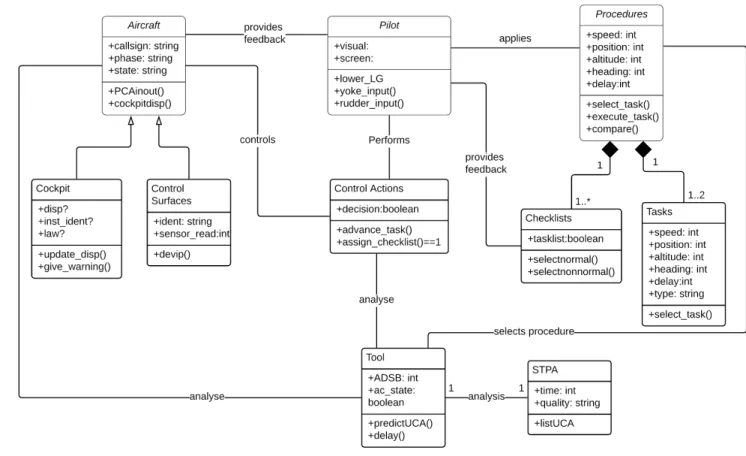
In this section we show how we used the above mentioned UML class diagram representation to model the pilot, proce-dures, and the cockpit. The overall idea of this interaction can be seen in figure 2.
Pilot takes visual inputs and information from the display screens and perform some actions on the aircraft by applying input to the control columns like yoke, thrust, flaps, rudder, and landing gear. These actions are given by Procedures that
Fig. 2. Process Diagram.
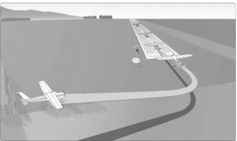
Fig. 3. Approach.
contain all the tasks needed to perform the landing and allows the pilot to execute the required task in a sequential order. To perform a task, the pilot provides a control action (landing gear lever down), this control action gives an input to the aircraft (electrical input). The aircraft processes it and gives corresponding control output (like, lowering of the landing gear by hydraulic actuation). The sensors check if the landing gear is down and locked, if yes, it is indicated to the pilot in the cockpit by three green lights and the approach is continued. If anything is in an incorrect position, the pilot receives a warning and he/she selects a non nominal procedure from the Quick Reference Handbook and switches to a different set of tasks (for example, they may perform a missed approach procedure by going around, in this case the task would be to increase throttle, pitch up, inform Air Traffic Controller, etc).
A. Landing Procedure
The landing procedures are published by regulatory au-thorities, airlines, and aircraft manufacturer based on their requirement like type of runway, special operating scenarios, etc. We use the generic landing procedure published by FAA in pilot handbook [4] mentioned in the following steps. This can also be seen in 3
• Turn Base (aviation term for aligning with the runway)
• Reduce Power to appropriate required level
• Extend the Flaps to position 1
• Lower the Landing Gear
• Flaps at position FULL
• Flare the aircraft to break the descent and maintain a smooth touchdown
• Touchdown
• Brake (Reverse thrust if required/available)
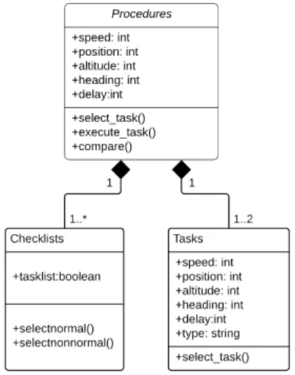
To model this we define a class called ”procedures” see figure 4
The attributes are:
• speed: it corresponds to the speed of the aircraft with respect to the wind, it is of type integer.
Fig. 4. Procedures UML
• position: it uses navigational aids and computes the distance from touch down point on the runway (it is in nautical miles, of type integer)
• altitude: during the approach phase pilots usually switch
from altitude with respect to the mean sea level to radio altitude, i.e., the altitude with respect to the ground just below the aircraft. (it is in feet, so type integer is used)
• heading: It is defined as the direction of the flight with respect to the true north. It is measured in degrees (from 1 to 360, integer)
• delay:delay in performing a task might lead to an abnor-mal scenario hence it is also used as an attribute to define the class. (it is measured in seconds, hence type integer) After the attributes we define the operations of this class:
• select task(): it selects the next task based on the position of the aircraft, for example when the aircraft is aligned to the runway, it will select lower landing gear.
• execute task(): Once the input is received from the pilot it will perform the desired task
• compare(): this operation will compare the task per-formed by the pilot and the task that must have been performed. Also the delay that was present while per-forming the task.
There are two sub-classes that depend on the parent class ”Procedures” they are ”Checklists” and ”Tasks”
The attributes of checklists are:
• tasklist: It is of type boolean and basically takes status of 1 (meaning task done) and 0 (missing task).
The operations are:
• selectnormal(): based on the state of the aircraft, if everything is normal this will be selected.
• selectnonnormal(): If there is a fault or failure, this will be selected.
Here we notice that the relationship has ”1 to many” cardinality this shows that there exists various checklists that
Fig. 5. Pilot UML
are performed when coming to land, and at the appropriate phase corresponding checklist is selected.
The attributes of class ”Tasks” are:
• speed: same as ”procedures”
• position: same as ”procedures”
• altitude: same as ”procedures”
• heading: same as ”procedures”
• delay: same as ”procedures”
• type: this is of type string that selects the type of tasks
to be performed based on the condition of the flight (nominal, non nominal)
After the attributes we define the operations of this class:
• select task(): it selects the next task to be performed. B. Pilot Modeling
The pilot has in his/her memory the list of task to be done for a procedure, he starts with the first task, gives an input to the aircraft (yoke, thrust, etc) and then sees the output, if the output is correct, he moves to the next task, and subsequently finishes the entire procedure successfully. However, if the output is not the expected one, he selects a new procedure to compensate for the incorrect state of the aircraft. For example, lets say the pilot is approaching the runway and gives the command to extend the flaps. The flaps have a faulty actuator and they dont extend. In that case the pilot uses a different procedure by increasing the speed of the aircraft to compensate for loss of high lift device (flaps) so that the aircraft doesn’t stall. The pilot then subsequently plans for a high speed approach and informs his intentions to the Air Traffic Controller. The thing that ensures that the procedures have been carried out is the checklist, it was purely verbal in the past but now we have electronic checklist that is partially verified/filled in by the aircraft systems. To better model this behavior of pilot in the cockpit we use UML model shown in 5
The attributes of class ”pilot” are:
• visual: it is of type string. It describes everything that the pilot is looking outside of the cockpit, for example, the runway, approach lights, etc.
• screen: also of type string that shows the information
available on the display screens inside the cockpit. The operations performed by class ”pilot” are:
• lower LG(): the pilot lowers the landing gear
• yoke input(): provides input on the control stick
• rudder input(): provides input on the rudder The attributes of class Control Actions are
• decision: it is of type Boolean that shows if the decision of performing a control action was taken or not. Following are the operations performed by this class:
• advance task(): based on the decision move to the next task
• assign checklist(): assign ”done” to the checklist.
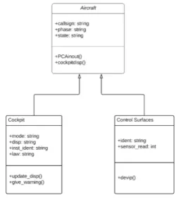
C. Aircraft
Aircraft class is the only physical component of our model. It represents two sub classes: cockpit and Control surfaces as seen in figure 6. The idea behind this block is to show how the pilot interacts with the aircraft. The attributes are
• callsign: it is the identifier of the aircraft, every flight has a unique identifier and is used by ATC to differentiate between various flights on ground and in sky. It is of the type string as it usually contains a string of letter or numbers, for example, British Airways flight 213 from London to Boston can have a callsign ”BAW13G” note that it is different from actual flight number. This is done in order to avoid confusion with flights that have similar number/pronunciation but belong to different airlines.
• phase: it tells us about the current phase of the flight, in our example case this is approach. It is also of type ”string”.
• state: it tells about the state of the components, ie,
if everything is working well or if there’s any failure present. It is of type ”string”.
After the attributes we define the operations of this class:
• PCAinout(): this provides signal to Primary Control Sur-faces like the Aileron, Elevators, Rudder, etc. It does so by converting pilot’s action on the control stick to an electric signal and then processing that electrical signal to the desired value and sends it to the actuator that controls the surface.
• cockpitdisp(): it shows the status of all the flight
param-eters on the display in cockpit.
As can be seen in the figure 6 we have the two sub classes, ”Cockpit” and ”Control Surfaces” that are linked to the class ”Aircraft” by the relation of association.
Cockpit class describes the interior process in the cockpit and control surfaces class explains what is happening on the exterior of the aircraft.
The attributes of cockpit are:
• mode: it informs about the corresponding mode, for example G/S (glide scope is active), LOC (on localizer), FLARE (aircraft performing flare just before touchdown), etc. It is of type ”string”.
Fig. 6. Aircraft UML
• disp: it is of type ”string” that shows the information on the display
• inst ident: it is also of ”string” type that shows what is to be displayed on the screen
The operations are:
• update disp(): display the current status and keep updat-ing
• give warning(): it shows the status of all the flight parameters on the display in cockpit.
The attributes of Control Surfaces are:
• ident: it informs about the corresponding mode, for example G/S (glide scope is active), LOC (on localizer), FLARE (aircraft performing flare just before touchdown), etc. It is of type string.
• sensor read: it reads the value from the sensor to check for the correct position and deflection of the control surface. (type integer)
The operations are:
• devip(): provide deviation to the control surface. D. Safety Analysis
To perform safety analysis of this process we add another class called ”STPA” (System Theoretic Process Analysis) is based on STAMP (System Theoretic Accident Model -Process) developed at MIT [5]. It translates any process to a controller-process model that has a controller which provides control actions to control the process. We use this method to assess the hazards that might be caused by improper control actions. In our case the pilot becomes the controller and the aircraft becomes the process. Based on the procedures, the pilot gives control actions to the aircraft. We try to analyze all the possible control actions and obtain their corresponding unsafe control action. This class uses inputs that check when and if a control action was provided and correspondingly gives a list of unsafe control actions. That enables the pilot to know
Fig. 7. Safety Analysis UML
what are the hazards corresponding to each unsafe control action that he might provide. This is seen in figure 8
The attributes of STPA are:
• time: It is of type ”string”.
• quality: it is of type ”string” and tells us if and when was a control action proveded (for example, landing gear lowered too late)
The only operation associated with this class is ”listUCA” that populates a table that contains all the possible unsafe control action.
Here the STPA block provides all the probable unsafe control action to the pilot. This becomes a very labor-intensive task if done manually by the pilot. In order to filter them and have only the relevant unsafe control actions provided to the pilot we add another block called tool.
The attributes of tool are:
• ADSB: It is of type ”string” and represents the data packet received from the aircraft.(Automatic dependent surveillancebroadcast (ADSB) is a surveillance technol-ogy in which an aircraft determines its position via satellite navigation and broadcasts it which is received by ground stations and other aircraft. This provides situational awareness to other aircraft and allow ATC to maintain separation. It usually contains data packets that has information about the flight like speed, heading, position, etc)
• ac state: shows the state of the aircraft (all ok, failure, atc)
The operations are:
• predictUCA(): based on the safety analysis method it predicts some unsafe control actions
• delay(): it shows the status of all the flight parameters on the display in cockpit.
To allow pilots to simulate the prediction of Unsafe Control Actions, we have developed a tool in MATLAB that takes into account the physical position of the aircraft and other flight parameters like speed, heading, and altitude. It combines these with the delay that might have been caused because of previous tasks and predicts the unsafe control action by selecting from the previously generated unsafe control actions. [6]
IV. INTEGRATION
Once we have specified the modelling for each of the components individually we move to integrating all of them
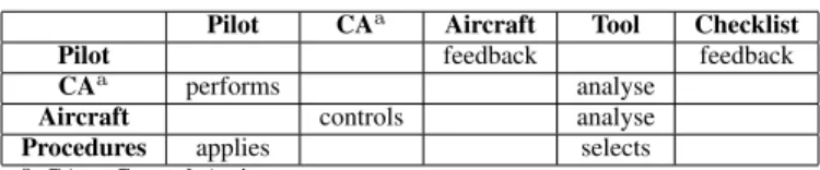
TABLE I TABLETYPESTYLES
Pilot CAa Aircraft Tool Checklist
Pilot feedback feedback
CAa performs analyse
Aircraft controls analyse
Procedures applies selects
aCA = Control Actions.
in one model. Apart from the connectors already used, we use association type of link as it can be used to show any relationship or logical connection between two classes. Table I summarizes the link between all the classes.
The names on top of the columns are the classes that act on other classes given in the first column. To explain in detail let’s start with the class pilot, as we can see Pilot performs some contron actions (CA) by applying the available procedures. The control action class provides a control output to the aircraft that enables correction in trajectory or any other desired action (like lowering the landing gear). Once the action has been performed in the aircraft’s control surface the class ”aircraft” provides feedback to the pilot about the state of the aircraft letting the pilot know if the action was done or not. The subclass ”checklists” from the procedures model also provides a feedback to the pilot about the checklists that they perform. If something is missing they can correct/perform the action and move to the next step. Next we move to the class ”tool”. It performs safety analysis using the before mentioned STPA process and takes into account the control actions, state of the aircraft (position and other parameters), and finally the procedures. If everything is ok after the analysis then the normal procedures are selected and continued but if something is not normal the pilot switched to non nominal procedures and the tasks are updated.
V. CONCLUSION
The idea of this paper was to show that it would be interesting to model various aspects of aircraft operations using techniques from software development. The paper presents a different approach to model the interaction of the pilot in the cockpit. This approach enables different actors like engi-neers, researchers to understand the integration in a common framework. It has many advantages, for example, the one we explored during the research which was to perform the safety analyses of the pilot tasks in the cockpit. This will help not only assessing the performance of the pilot in the cockpit but will also help define the functionalities of the cockpit of the future. We can have real time safety analysis that can be built over this model that check for past pilot inputs and based on the way he/she pilots the aircraft propose future actions to optimize safety/economy or provide warnings in case of potential mistakes. This also enables design engineers to define better procedures that reduce the chances of error and improve the overall piloting experience and safety of the aircraft.
Fig. 8. Process Diagram.
ACKNOWLEDGMENT
The ongoing research is being funded by Dassault Avia-tion. The project is under the ISAE-SUPAERO and Dassault Aviation chaire titled CASAC.
REFERENCES
[1] Loss of Thrust in Both Engines After Encountering a Flock of Birds and Subsequent Ditching on the Hudson River US Airways Flight 1549 Airbus A320214, N106US Weehawken, New Jersey January 15, 2009. Accident Report NTSB/AAR-10/03 PB2010-910403
[2] Aircraft Accident Investigation Report PT. Lion Mentari Airlines Boeing 737-8 (MAX); PK-LQP Tanjung Karawang, West Java Republic of Indonesia 29 October 2018.
[3] Aircraft Accident Investigation Preliminary Report Ethiopian Airlines Group B737-8 (MAX) Registered ET-AVJ 28 NM South East of Addis Ababa, Bole International Airport March 10, 2019
[4] FAA Manual, Airplane Flying Handbook (FAA-H-8083-3B), Chapter8: Approaches and Landings. 2016
[5] Leveson, N. G. (2011). Engineering a Safer World: Systems Thinking Applied to Safety, The MIT Press.
[6] Vatsal Pant, Jean-Charles Chaudemar, Hamid Demmou. Safety Analysis of Pilot-System Interaction. 12e Confrence Internationale de Modlisa-tion, Optimisation et Simulation (MOSIM), Jun 2018, Toulouse, France. 6p. hal-01828560