Publisher’s version / Version de l'éditeur:
Journal of the Acoustical Society of America, 90, 3, pp. 1146-1153, 1991
READ THESE TERMS AND CONDITIONS CAREFULLY BEFORE USING THIS WEBSITE. https://nrc-publications.canada.ca/eng/copyright
Vous avez des questions? Nous pouvons vous aider. Pour communiquer directement avec un auteur, consultez la première page de la revue dans laquelle son article a été publié afin de trouver ses coordonnées. Si vous n’arrivez pas à les repérer, communiquez avec nous à [email protected].
Questions? Contact the NRC Publications Archive team at
[email protected]. If you wish to email the authors directly, please see the first page of the publication for their contact information.
NRC Publications Archive
Archives des publications du CNRC
This publication could be one of several versions: author’s original, accepted manuscript or the publisher’s version. / La version de cette publication peut être l’une des suivantes : la version prépublication de l’auteur, la version acceptée du manuscrit ou la version de l’éditeur.
Access and use of this website and the material on it are subject to the Terms and Conditions set forth at
Controlling interoffice sound transmission through a suspended ceiling
Halliwell, R. E.; Quirt, J. D.
https://publications-cnrc.canada.ca/fra/droits
L’accès à ce site Web et l’utilisation de son contenu sont assujettis aux conditions présentées dans le site LISEZ CES CONDITIONS ATTENTIVEMENT AVANT D’UTILISER CE SITE WEB.
NRC Publications Record / Notice d'Archives des publications de CNRC:
https://nrc-publications.canada.ca/eng/view/object/?id=6317202e-7ce8-4096-9125-ed1bfee3b3eb https://publications-cnrc.canada.ca/fra/voir/objet/?id=6317202e-7ce8-4096-9125-ed1bfee3b3eb
R e f
S e r
TH1
N21d
National Research
Conseil national
n,
1 7 1 0 * 1
c
ouncil Canada
de recherches Canada
1 9 9 1
BLDG,
Institute for
lnstitut de
- -
Research in
recherche en
Construction
construction
Controlling Interoffice Sound Transmission
Through a Suspended Ceiling
by R.E. Halliwell and J.D. Quirt
Reprinted by
Journal of the Acoustical Society of America
Vol. 90, No. 3, September 1991
pp. 1 146-1 153
(IRC Paper No. 1710)
Controlling interoffice sound transmission through
a suspended
ceiling
R. E. Halliwell and J. D. Quirt
Institute for Research in Construction, National Research Council Canada. Ottawa, Ontario KIA OR6, Canada
(Received 7 February 199 1; accepted for publication 29 April 199 1 )
A simple, economical technique is discussed to improve the noise reduction between adjacent offices where the dominant sound transmission path is through the suspended ceiling and the common plenum above the ceiling. A series of laboratory measurements has been made to determine the important physical parameters associated with using a stack of absorptive batts as a sound barrier. These are compared with measurements made of an installation in a commercial office building. Further studies are required to evaluate the effect on air quality. PACS numbers: 43.55.Rg, 43.55.Ti
INTRODUCTION
Modern office buildings in North America are com- monly designed with large office areas where all services (in- cluding electricity, plumbing, and air supply ducts) are in- stalled above a suspended ceiling. Using the space above the suspended ceiling as a plenum for air return and installing all other services through this space permits offices constructed with demountable walls to be built anywhere in the space to suit the occupants' needs. If those needs change, it is fairly simple to change the office layout with minimal alteration of the basic building.
In most situations where design is optimized for one feature, other features are compromised. To maintain flexi- bility, the office partitions commonly extend only up to the underside of the suspended ceiling. Providing this flexibility tends to limit acoustical isolation between offices because sound transmission through the suspended ceiling, across the plenum space above, and back down through the ceiling of another office can bypass the nominal noise barrier pro- vided by the interoffice partition.
The path through the open plenum space above the sus- pended ceiling usually provides only a few decibels of attenu- ation. Hence, most of the attenuation between offices is pro- vided by the suspended ceiling system. Some types of ceiling panels (such as glass fiber) provide little attenuation, and even if panels with high transmission loss are used, the at- tenuation is commonly limited by leaks.
The leaks include cracks between the edges of each ceil- ing panel and the supporting T-bar grid, and openings to permit ventilation air flow from the offices up into the re- turn-air plenum above the ceiling. In typical installations using mineral fiber ceiling panels, the combination of cracks and air-return openings limits the interoffice sound attenu- ation to the equivalent of what would be transmitted through a partition whose sound transmission class (STC) is about 35. The use of glass fiber ceiling panels gives even lower sound reduction. In either case, substantially im- proved sound reductions are required to ensure speech pri- vacy.
The sound reduction can be increased by either of two
methods: reducing transmission through the suspended ceil- ing (including treatment of air-return openings), or by blocking sound transmission through the space above the suspended ceiling. This paper concentrates on the latter method, documenting the performance of a simple design that appears to offer an optimal combination of simple in- stallation, low impact on ventilation, and good acoustical performance.
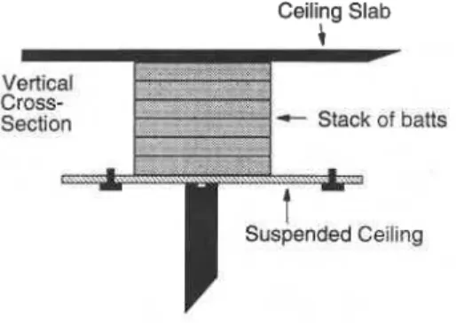
A stack of absorptive batts is used to block the space from the top of the interoffice partition to the slab above, as illustrated in Fig. 1. The key features of the material are compressibility (which permits stuffing the material around ducts and pipes), resilience (which causes it to puff up to fill cracks and to hold the stack in place), and acoustical absorp- tion. Glass fiber thermal insulation batts were used for most of the work reported here, but, in principle, any resilient material with similar flow resistance would provide compar- able results. For ease of reference, this construction tech- nique is referred to in this paper as a "fuzzwall."
This approach was considered because it offers potential benefits both in ease of installation and in reliability of per- formance relative to the traditional approach of extending partitions up to the slab above. Installing wall surfaces around a tangle of pipes is labor intensive (and hence expen- sive), leaks around penetrations are likely both in initial con- struction and when additional services are added later, and a
Ceiling Slab
L Vert~cal
Cross-
Section + stack of baHs
FIG. 1. Basic fuzzwall configuration.
solid partition blocks return air flow. Installing a fuzzwall to block the space above the partition offers practical advan- tages in all these respects, as detailed below.
Further studies are required to evaluate the effect on air quality (air flow, particulates, etc.) before the concept can be confidently endorsed for general use.
The following section describes the laboratory facility and test method used for most of the work reported here. Subsequent sections discuss factors controlling sound trans- mission through the stack of absorptive batts, and practical limitations imposed by typical suspended ceiling installation details. Results of preliminary field tests are also presented. This is not really a new technique. The idea was men- tioned by Heckl' in his Fairey Memorial Lecture, and the authors are aware of acoustical consultants who have used similar constructions. There has not, however, been any published discussion of the important parameters or of the effectiveness of the technique.
I. LABORATORY MEASUREMENT PROCEDURES
Basically, the facility and the test method are similar to those developed by Hamme for the Acoustical Manufac- turers Association test of sound transmission through sus- pended ceiling systems.' Many suspended ceiling systems have been tested in such facilities according to the AMA standard. A similar test method has been developed by the International Standards Organi~ation,~ and a draft ASTM standard4 will soon provide an updated version of the AMA procedure. A comparison of these test methods will be the subject of a future paper. The laboratory facility and test method used for this study comply fully with the ASTM draft standard.
This laboratory facility is a hard-walled rectangular box
8.7 m long, 4.5 m wide, and 3.55 m high. A suspended ceiling is installed 2.8 m above the floor, as shown in Fig. 2. A parti- tion divides the space into two rooms whose length (and volume) differ by 10%; sound attenuation by this partition is discussed below. This partition extends only up to the sus- pended ceiling; the opening above the ceiling is 0.75 m high. Above the suspended ceiling, the walls are lined with acous- tical foam whose random incidence absorption coefficient is greater than 0.85 for the frequency range of interest.
FIG. 2. Side view of test rooms. As discussed in the text, each room con- tained five microphones and two loudspeakers. All tests were repeated with each room as the source room.
The normalized sound attenuation D, is given by
where L, is the average sound pressure level in the source room, L, is the average sound pressure level in the receiving room, A, is the absorption in the receiving room, and A, is the reference absorption area, equal to 12 metric Sabins.
The intent of the test method is to measure sound trans- mission from one room to the other via the suspended ceiling and the space above, in a facility intended to mimic typical offices. The absorptive lining of the walls above the suspend- ed ceiling simulates the effect of sound spreading away into the extended open space above adjoining offices. The term
- 10 log(A,/A, ) normalizes the result to the level differ- ence that would be observed if absorption in the receiving room were equal to A, (i.e., equal to 12 metric Sabins)
.
Since12 m2 is also the area of the separating partition (and a rea- sonable approximation of typical office partition areas), this provides the sound attenuation rating in a form directly comparable with the partition's transmission loss. This ap- proach permits designers to combine the ceiling attenuation data directly with partition transmission loss data using the usual process for multicomponent partitions and (after an adjustment for expected receiving room absorption) to esti- mate actual interoffice noise reduction.
The sound-pressure level in each room was sampled by five Bruel & Kjaer 4149 (12 mm) microphones on B&K
2619 preamplifiers, connected via B&K 281 1 microphone multiplexers to a Norwegian Electronics type 830 real time analyzer. This data acquisition system was controlled by a minicomputer which also controlled the sound sources in both rooms. Each room had two loudspeakers (aimed into the corners farthest from the partition) driven simulta- neously by independent amplifiers with separate (incoher- ent) noise generators.
Each measurement was the average result from four subtests. For each subtest, background sound levels were checked. With white noise generated through the loudspeak- ers in one room, the energy average sound-pressure level in the source room (L, ) was determined from 30-s equivalent sound-pressure levels measured at the five microphones in the source room, and the corresponding energy average (L,) was determined from the five microphones in the re- ceiving room. The absorption (A, ) was calculated from the average reverberation time measured from five decays at each of the five microphones in the receiving room. The sub- test was then repeated using the other room as source room. Then all ten microphones were moved to different positions, and the subtest was repeated for both directions. This exten- sive sampling of the sound fields ensured good precision de- spite the significant variation in sound-pressure levels in these small and nonreverberant rooms.
To verify the reproducibility of measurements within the laboratory, precision estimates were obtained by system- atic repeats of measurements on a typical mineral fiber ceil- ing system. The complete measurement was repeated three times, without modifying the specimen but removing and repositioning the microphones and diffusing panels (the only changeable elements) from test to test. Two further
tests were performed removing and reinstalling both the mi- crophones and all the ceiling panels. The five measured re- sults are presented in Fig. 3(a). The five results are nearly indistinguishable; the larger variation in the range from 1-3 kHz is believed to be due to changes in leakage when the panels were reinstalled. The standard deviation for the five tests is given in Fig. 3(b) on a finer scale. Taking this as an estimate for the standard deviation of the results in this labo- ratory, results should match within twice this range, 19 times out of 20. Thus, for most frequencies, variations of even 1 dB indicate real change in ceiling system perfor- mance.
The flanking limit is another characteristic essential to assessing measurements from any facility. In addition to the nominal transmission path though the suspended ceiling and the space above, some sound energy is also transmitted through the partition separating the two rooms and by struc- tural flanking paths. This obviously determines the highest values of ceiling attenuation that can be legitimately mea- sured. The flanking limit was measured by blocking the ple- num space above the suspended ceiling with a partition nom- inally equivalent to the partition below.
The partition had two layers of damped steel sandwich panels, each 28.3 kg/m2, separated by a glass fiber-filled cav- ity that tapered from a separation of 7.5 cm at the top to 30 cm at the bottom. The observed attenuation is roughly con- sistent with that expected for the partition.
The area of the graph above the measured attenuation with the steel blocking wall in place is shaded grey in Fig. 4 and subsequent graphs to indicate this flanking limit. The data presented were not systematically corrected for flank- ing, but where results are within 10 dB of the limit, it should be recognized that the apparent attenuation is systematically
-38i 160 315 630 1.25k 2 . i k 5; 113 Octave Frequency, Hz
FIG. 3. Normalized attenuation and standard deviation for five successive measurements of a ceiling system. The dashed curves are for measurements after re-installing the ceiling.
113 Octave Frequency, Hz
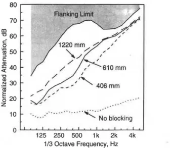
FIG. 4. Effect of changing the thickness of a fuzzwall installed with a 19- mm glass fiber ceiling. The values are STC 32 with a 406 mm thick blocking wall, STC 42 with a 610-mm-thick blocking wall, and STC 49 with a 1220- mm-thick blocking wall. The dotted curve is the normalized attenuation for the same suspended ceiling with no blocking (STC 14).
reduced from the attenuation through the nominal ceiling and partition system.
II. SOUND ATTENUATION BY A FUZZWALL
The acoustical performance of an absorptive blocking wall depends on the thickness, the density, and the flow re- sistivity of the absorptive batts used. The readily available absorptive batts were found to have flow resistivities in a fairly narrow range so only the thickness and density were considered as practical variables.
Increasing the thickness of a fuzzwall increases both the mass of the wall and the depth of absorptive material through which the sound must pass. The normalized attenu- ation for various thicknesses of blocking wall with a sus- pended ceiling of glass fiber panels is shown in Fig. 4. It can be seen that the attenuation at mid frequencies is strongly dependent on the thickness of the blocking wall. This trend should extend to high frequencies, but above about 1 kHz the flanking limit of the facility limited the apparent attenuation for this ceiling system. At low frequencies, the propagation losses due to flow resistance are lower, and this is reflected in smaller increases in the normalized attenuation between rooms. The dotted curve is the normalized attenuation of the ceiling system without any blocking and provides a reference for judging the effectiveness of the stack of batts as a block- ing material.
The effects of increasing the mass and thickness can be separated to some degree by using material of different den- sities. Figure 5 shows the results for three glass fiber materi- als having densities of 12.8,28.9, and 48.2 kg/m3. The medi- um- and high-density materials have very similar flow resistivities ( 1.2 X lo4 mks rayls/m), about twice that of the low-density batts ( 6 X lo3 mks rayls/m) which were con- ventional thermal insulation batts. The reduced attenuation provided by the low-density batts may be attributed to both
125 250 500 l k 2k 4k
113 Octave Frequency, Hz
FIG. 5. Effect of changing the density of a fuzzwall installed with a 19-mm glass fiber ceiling. The values are STC 39 with a 610-mm-thick blocking wall of low density batts (12.8 kg/m3), STC 48 with a 812-mm-thick blocking wall of medium density batts (28.9 kg/m3), and STC 47 with a 610-mm-thick blocking wall of high-density batts (48.2 kg/m3). The dot- ted curve is the normalized attenuation for the same suspended ceiling sys- tem with no blocking (STC 14).
the decrease in density and the decreased flow resistivity. The medium-density batts were actually 1/3 thicker than the others and showed a higher normalized attenuation than the high-density batts. This indicates that there is a stronger dependence on the thickness than on the mass in the mid- to high-frequency range. Again, the apparent attenuation is limited by the flanking from the nominal value for these sys- tems.
The attenuation through a fuzzwall can be calculated using the procedures developed by Bies and Hansen516 and by Shultz7 These procedures are applicable at high frequen- cies where the wavelength within the batt is less than the thickness of the blocking wall, and at low frequencies when the wavelength in the batt is greater than ten times the fuzz- wall thickness. For the case of a 406-mm-thick wall of batts,
the attenuation can be calculated for 1/3 oct frequencies
greater than 500 Hz and less than 80 Hz. Figure 6 shows the
estimated attenuation (assuming a linear interpolation be- tween 80 and 500 Hz, added to the measured attenuation for a glass fiber ceiling) and the measured attenuation for a 406- mm-thick fuzzwall of absorptive batts with the same glass fiber ceiling system. As can be seen, the agreement is quite good. Estimates for thicker blocking walls cannot be mean- ingfully compared with measured results because the results are compromised by flanking.
Ill. PRACTICAL INSTALLATION DETAILS
This section discusses the effect of typical installation details on the attenuation provided by a suspended ceiling system with absorptive batts blocking the plenum space.
Details at the ceiling partition junction have a signifi- cant effect on the performance of a ceiling-fuzzwall system. This is demonstrated in Fig. 7 for a glass fiber ceiling system. Three different ceiling-partition junctions [illustrated in Fig. 7 ( a ) ] are examined, one with both the T-bar grid and
O " a
id5*
*iOa
;;om
'1;' '2;' *;k4'113 Octave Frequency, Hz
FIG. 6. Comparison of predicted (STC 37) and measured (STC 37) attenu- ation for a 400-mm-thick fuzzwall installed with a 19-mm glass fiber ceiling system. The dotted curve is the normalized attenuation for the same sus- pended ceiling system with no blocking (STC 14).
the ceiling panels continuous over the partition, one with the T-bar grid continuous and the ceiling panels discontinuous, and one with both the T-bar grid and the ceiling panels dis- continuous. There are two processes causing the reduced performance when both grid and ceiling panel are contin- uous. First, there is a leak between the ceiling panels and the partition top. Second, waves propagate along the ceiling panels and radiate into the other room. This was demon- strated by simply cutting the ceiling panels above the top of the partition so that they were no longer continuous. As can be seen in Fig. 7(b), this provides a general increase in per- formance at all frequencies, but most notably at high fre- quencies. Splitting the grid as well as the ceiling panels by adding a small cap on top of the partition between the two rooms eliminates any leakage under the ceiling panels and further boosts the high-frequency performance. It should be noted that, when no blocking is present, the details of the partition-ceiling junction have little effect on the observed sound attenuation.
Figure 8 shows the attenuations obtained for the same three'ceiling-partition junction conditions, but for a mineral fiber ceiling. The same behavior is observed, except that in this case the high-frequency performance is limited by flank- ing. Because the glass fiber ceiling panels examined in Fig. 7 are quite flexible, the weight of the absorptive batts tends to press them down to close the leak at the top of the partition. This does not happen with the more rigid mineral fiber pan- els, so there is a more noticeable leak with the continuous ceiling and a much greater improvement when both the grid and ceiling are made discontinuous.
To put the value of a fuzzwall in perspective, Fig. 9 illus- trates interoffice sound attenuation with the same mineral fiber suspended ceiling system but no blocking of the ple- num. With the ceiling normally installed but without air- return openings, measurement according to the AMA test method gave a ceiling sound transmission class (STC) of 33,
113 Octave Frequency, Hz
FIG. 7. ( a ) Details of partition ceiling junction. ( b ) Effect of changing partition-ceiling junction details for a 610-mm-thick fuzzwall installed with a 19-mm glass fiber ceiling system. The values are STC 39 with a con- tinuous ceiling and grid, STC 43 with split ceiling panels and a continuous grid, and STC 42 with split ceiling panels and split grid. The dotted curve is the normalized attenuation for the same ceilings with no blocking (STC 14).
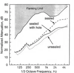
corresponding closely to the manufacturer's rating for the product. Sealing all cracks between the ceiling panels and the supporting T-bar grid with duct tape increased the at- tenuation to STC 39, with attenuation increased by more than 10 dB at the higher frequencies. Introducing a hole of 0.1 m2 ( 1.0 sq. ft) in the ceiling of each room to simulate typical air return openings reduced the attenuation above 1000 Hz to essentially that observed before sealing the cracks. Given that normal installations include both leaks around the panels and openings for air return to the plenum, even the best ceiling panels will not give much better perfor- mance than this last case. Figure 10 shows that this same installation with a 610-mm-thick fuzzwall will achieve an STC of 49. The 0. 1-m2 hole in the ceiling of each room has
" \\-a P % C FMhking Limit "
-
-
-
-
-
-
113 Octave Frequency, HzFIG. 8. Effect of changing partition-ceiling junction details for a 610-mm- thick fuzzwall installed with a 16-mm mineral fiber ceiling system. The val- ues are STC 49 with a continuous ceiling and grid, STC 53 with split ceiling panels and a continuous grid, and STC 49 with split ceiling panels and split grid. The dotted curve is the normalized attenuation for the same ceilings with no blocking (STC 32).
little effect on the attenuation or the STC when a fuzzwall is present. This means that the care taken during installation of the ceiling and the details of the ventilation openings are not as critical to the overall performance as would normally be the case.
Since the plenum space is usually used as an air return, it is normally necessary to provide a path for the flow of return air through any form of blocking wall. To facilitate this, openings can be put through the blocking wall of batts to create what is in effect a lined duct through the wall. Figure 11 shows a comparison of three blocking wall configura-
Flanking 1 7
l o 0
0
125 250 500 lk 2k 4k113 Octave Frequency, Hz
FIG. 9. Effect of introducing a hole into 16-mm mineral fiber ceiling. The values are STC 33 for a normal unsealed installation, STC 39 with all grid joints sealed with duct tape, and STC 37 with all grid joints sealed but a 0.1- m2 hole in the ceiling of each room.
FIG. 13. Plan view of offices ( a ) before blocking wall installation and ( b ) after installation of absorptive batt blocking walls.
transmission measurements were repeated, and the results compared to laboratory measurements.
Interoffice noise reduction measurements were made using a Norwegian Electronics NE-830 analyzer with a Bruel & Kjaer 4149/2619 microphone system and a Tra- coustics NS-100 noise source. These measurements conform in all respects to ASTM E336-84 (Ref. 8) (except that room size is below the limits for designation of, the results as field sound transmission loss for bands below 200 Hz). Sound decay measurements were made with the same equipment in accordance with ASTM E336-84.
In this particular installation the four offices affected were surrounded by an open-plan office on three sides and more private offices on the fourth. Thus it was necessary to provide acoustical protection on all four side of each office. In general, the number of sides of an office above which a fuzzwall should be installed will depend on the office layout and the location of noise sources. In some cases it may be advantageous to wrap the fuzzwall around a corner to pre- vent flanking. Simply extending the fuzzwall beyond the partition would also prevent flanking, but unless the ceiling system is rigid and strong enough there may be bowing of the ceiling due to the pressure exerted by the fuzzwall.
Figure 14 shows the range of interoffice noise reduction, measured before and after the blocking walls were installed. The measured noise isolation class (NIC) values without blocking range from 17-22, which is far below what would be required for speech privacy, but consistent with laborato- ry tests on similar ceilings. The NIC values achieved with the blocking range from 35 to 39, and are comparable to those
-
With blocking NIC 35-
39-
-
-
-
No blocking 1 . # 1 . . 1 . . 1 . . 1 . . 1 . 1 1 1 u 125 250 500 1000 2000 4000 113 Octave Frequency, HzFIG. 14. Range of noise reduction values before and after installation of absorptive batt blocking.
typically observed with a good suspended ceiling system. Figure 15 compares the field measurements with labora- tory data for a 406-mm-thick absorptive batts with a ceiling of Fiberglas Nubby I11 panels (which should have similar performance to the ceiling in these offices). Apparent field sound transmission class (FSTC) was calculated according to ASTM E413-87 (Ref. 9), treating the partition separating the offices as the nominal sample. This provides a standard measure of the interoffice sound insulation that can be com- pared directly with laboratory tests on partitions (according to ASTM E90 (Ref. 10) ) or suspended ceilings (according to AMA 1-11, etc. )
.
The laboratory and field data show good agreement except at high frequencies, where the field results show a noticeable dip around 3 kHz. This is consistent with the limit expected due to transmission through the gypsum wallboard partitions.125 250 500 1000 2000 4000 113 Octave Frequency, Hz
FIG. 15. Comparison of field transmission loss results with laboratory nor- malized attenuation for a similar ceiling system having an STC = 34.
It is useful to compare costs of installation for a fuzzwall with conventional blocking. During the installation of the fuzzwall at this site, the same company had the space above one wall of a conference room blocked using gypsum wall- board and lead sheeting. It took six workmen the same length of time to install 20 ft of gypsum wallboard and lead blocking as was required for three men to install 120 ft of fuzzwall. The cost reduction per linear foot for labor alone is a factor of 12, not to mention the reduced material costs. In another situation it was estimated that the cost for materials to install a fuzzwall was one-third of that for extending the partitions to the slab above.
DISCUSSION AND CONCLUSIONS
The absorptive batt blocking wall, or fuzzwall, provides a simple, economical means of increasing the sound insula- tion between offices without compromising the advantages of the open plenum construction. It is a simple matter to provide for air flow through the wall yet still provide sound insulation comparable to that of the partition used below the ceiling.
A study is underway on the effect of the fuzzwall on air flow and how it changes the effective air supply to offices. It is expected that this will be reported in the near future.
It is not known what, if any, effect a fuzzwall might have on the amount of particulate matter in the air supply. Clear- ly, there may be a potential health risk involved and this question should be addressed before the technique is en- dorsed for general use. It is unlikely, however, that an ab-
sorptive batt blocking wall would introduce significantly more particulate matter than does using a glass fiber ceiling or glass fiber air filter elsewhere in the return air path.
ACKNOWLEDGMENTS
The authors gratefully acknowledge financial support of this study by Public Works Canada and by Fiberglas Can- ada.
'M. Heckl, "The Tenth Sir Richard Fairey Memorial Lecture: Sound Transmission in Buildings," J. Sound Vib. 77(2), 165-189 ( 1981 ).
'AMA-1-11-1967 Method of Test, "Standard Specification for Ceiling Sound Transmission Test by Two-Room Method," Acoustical Materials Association, New York ( 1967).
IS0 140/9- 1985 (E), "Acoustics-Measurement of Sound Insulation in Buildings and of Building Elements-Part 9: Laboratory Measurement of Room-to-room Airborne Sound Insulation of a Suspended Ceiling with a Plenum Above It," International Organization for Standards ( 1985). ASTM, "Proposed Standard Method of Test for Airborne Sound Attenu- ation between Rooms Sharing a Common Ceiling and Plenum," Ameri- can Society for Testing Materials Draft 13a, Philadelphia ( 1990). D. A. Bies and C. H. Hansen, "Flow Resistance Information for Acousti- cal Design," Appl. Acoust. 13, 357-391 ( 1980).
6D. A. Bies, Noise and Vibration Control edited by L. Beranek (McGraw- Hill, New York, 1971 ), Chap. 10.
'T. J. Shultz, Noise and Vibration Control edited by L. L. Beranek (McGraw-Hill, New York, 1971), Chap. 15.
ASTM-E336-84, "Standard Test Method for Measurement of Airborne Sound Insulation in Buildings," American Society for Testing and Mate- rials (1984).
ASTM E413-87, "Classification for Rating Sound Insulation," American Society for Testing and Materials ( 1987).
I0ASTM E90, "Standard Test Method for Laboratory Measurements of Airborne Sound Transmission Loss of Building Partitions," American Society for Testing and Materials ( 1987).