Publisher’s version / Version de l'éditeur:
Vous avez des questions? Nous pouvons vous aider. Pour communiquer directement avec un auteur, consultez la première page de la revue dans laquelle son article a été publié afin de trouver ses coordonnées. Si vous n’arrivez pas à les repérer, communiquez avec nous à [email protected].
Questions? Contact the NRC Publications Archive team at
[email protected]. If you wish to email the authors directly, please see the first page of the publication for their contact information.
https://publications-cnrc.canada.ca/fra/droits
L’accès à ce site Web et l’utilisation de son contenu sont assujettis aux conditions présentées dans le site LISEZ CES CONDITIONS ATTENTIVEMENT AVANT D’UTILISER CE SITE WEB.
The 27th American Towing Tank Conference [Proceedings], 2004
READ THESE TERMS AND CONDITIONS CAREFULLY BEFORE USING THIS WEBSITE.
https://nrc-publications.canada.ca/eng/copyright
NRC Publications Archive Record / Notice des Archives des publications du CNRC : https://nrc-publications.canada.ca/eng/view/object/?id=9daa68f8-f1d5-451b-9599-2491e56e6a91 https://publications-cnrc.canada.ca/fra/voir/objet/?id=9daa68f8-f1d5-451b-9599-2491e56e6a91
NRC Publications Archive
Archives des publications du CNRC
This publication could be one of several versions: author’s original, accepted manuscript or the publisher’s version. / La version de cette publication peut être l’une des suivantes : la version prépublication de l’auteur, la version acceptée du manuscrit ou la version de l’éditeur.
Access and use of this website and the material on it are subject to the Terms and Conditions set forth at
An experimental model for ice performance of podded propellers
27th American Towing Tank Conference St. John’s, Newfoundland and Labrador Canada, August 6 and 7th, 2004
AN EXPERIMENTAL MODEL FOR ICE PERFORMANCE OF PODDED PROPELLERS
J. Wang / Memorial University of Newfoundland A. Akinturk / Institute for Ocean Technology
W. Foster / Institute for Ocean Technology
S. J. Jones / Institute for Ocean Technology
N. Bose / Memorial University of Newfoundland
ABSTRACT
This paper describes the experimental model designed and built at Institute for Ocean Technology (IOT) to measure the ice performance of the podded propulsors in the ice tank. The model is capable of measuring forces and moments on the overall system, propeller shaft bearing loads and the loads on the blade during different operating conditions. Some results obtained from the ice tank testing are presented. Additionally, test conditions for ice performance are discussed.
INTRODUCTION
Recently, with the growing interest in the podded propulsors and with the increasing applications of this system, the number of icebreakers or ice-going vessels that have podded propulsors is increasing. As sea route developments and natural resource explorations in arctic or sub-arctic regions are increasingly carried out, the number of vessels capable of navigating in ice infested seas should be increased. Therefore, this paper presents the findings of the research carried out to investigate the performance of podded propulsors in ice conditions using ice tank experiments. Ice loads acting on the pod system were analyzed and the interactions between ice and propeller was considered.
An azimuthing pod system is a fully assembled propulsion unit and is also a steering unit without a general rudder. Inside the pod, there is an electric motor, which transfers power and signals from the ship through the strut. General benefits of podded propulsors are as follows: high steering ability, low level of noise and vibrations, increased payloads, lower operating cost, high ice going capability in astern direction, time saving during port calls and so on (Niini, 1997; Muller, 1999; Kron and Holmstrom, 1999; van Terwisga, 2001). There is some restriction of speed and power, however, which is caused by the capability and size of the electric motor and high manufacturing cost (Mewis, 2001).
So far, several experimental tests with model propellers had been carried out in the ice tank (Searle, 1999; Moores, 2002). These tests focused on ice loadings on the propeller blade, and the test results can be compared with those of this study. A few studies of podded propulsors in ice conditions have been performed (Niini, 1995; Juurmaa, 2001; Akinturk et al., 2004).
An azimuthing pod experimental model for this study consists of 0.95 meter long, 0.17 meter in diameter pod housing, 0.45 meter high streamlined strut and 0.3 meter propeller diameter. The ice tests were carried out at the IOT ice tank with various conditions. The open water tests were carried out in the same condition as ice tests. The EG/AD/S model ice (Timco, 1986) was used for these experimental tests.
NOMENCLATURE T Propeller Thrust Q Propeller Torque D Propeller Diameter r Propeller Radius P Propeller Pitch V Carriage Speed
X X-Axis of Global Dynamometer Y Y-Axis of Global Dynamometer Z Z-Axis of Global Dynamometer Xa X-Axis of Aft Dynamometer Ya Y-Axis of Aft Dynamometer Za Z-Axis of Aft Dynamometer Xb X-Axis of Blade Dynamometer Yb Y-Axis of Blade Dynamometer Zb Z-Axis of Blade Dynamometer Xf X-Axis of Forward Dynamometer Yf Y-Axis of Forward Dynamometer Zf Z-Axis of Forward Dynamometer KT Thrust Coefficient
KQ Torque Coefficient FX Force on X-Axis FY Force on Y-Axis FZ Force on Z-Axis MX Moment on X-Axis MY Moment on Y-Axis MZ Moment on Z-Axis
n Propeller Rotating Speed (Revolutions Per Second) w Angular velocity
hi Depth of cut
EXPERIMENTAL MODEL
Azimuthing podded propulsor model was designed and built at IOT for measuring forces and moments on each parts. In this experimental model, there are four six component dynamometers; (1) blade dynamometer at the root of one of the blades, (2) aft bearing dynamometer on the propeller drive shaft inside the pod, (3) fore bearing dynamometer on the propeller drive shaft inside the pod, (4) global dynamometer above the strut (Figure 1). These dynamometers measure the individual forces and moments acting at each position. In particular, the global dynamometer measures the global forces on the whole system: propeller, pod and strut.
Figure 1: Assembled model with local axis
Depth of cuts, carriage speeds, propeller rotating speeds, azimuthing angles, and properties of the model ice were measured and recorded. Figure 2 shows the definition of depth of cut.
Depth of Cut
ICE
Path of Blade Tip
Figure 2: Definition of depth of cut
EXPERIMENTAL FACILITY
The tests were conducted in the ice tank at the National Research Council of Canada’s Institute for Ocean Technology (Jones, 1987). The useable area of the tank for ice testing is 76 m long, 12 m wide and 3 m deep. In addition, a 15 m long setup area is separated from the ice sheet by a thermal door to allow equipment preparation while the test sheet is prepared (Figure 3). The range of the carriage velocity is from 0.0002 to 4.0 m/s. The carriage is designed with a central testing area where a test frame, mounted to the carriage frame, allows the experimental setup to move transversely across the entire width of the tank. All tests were recorded by four cameras; two were on the carriage, the others were under the water.
Figure 3: Schematic diagram of the ice tank TEST PROCEDURE
There were four different tests: open water tests in tractor mode, open water tests in pusher mode, ice tests in tractor mode, and ice tests in pusher mode. Basically, each group of tests included three different propeller rotational speeds, two or three different carriage speeds, two different depths of cut, and different azimuthing angles from 0 to 180 degrees at 30 degrees intervals.
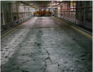
Ice tests were carried out with partially pre-sawn ice sheets (Figure 4) and pack ice (figure 5). Most ice tests were performed with 60 mm thickness of the ice and 80 kPa flexural strength of the ice. Several runs were tested with 80mm of ice thickness. During the tests, some of the data collection channels were saturated a few times (up to 3% of the total data points collected at the maximum). Table 1 shows the test matrix for this study.
Table 1: Test Matrix
Pod Mode Tractor Mode, Pusher mode Carriage Speed 0, 0.2, 0.5, 0.8 m/s Propeller Rotating Speed 5,7,10 Hz
Depth of Cut 15mm, 35mm Azim. Angle (Pusher Mode) 0, 30, 60degree Azim. Angle (Tractor Mode) 180, 150, 120degree
Ice Condition Pre-sawn Ice, Pack Ice Ice Thick. / Flex. Strength 60mm / 80kPa
50 cm 45o Model stern Pod Propeller Pre-sawn ice Center path
South quarter path North quarter path Thermal Barrier Door
Figure 4: Sketch for Pre-sawn ice sheet
Figure 5: Pack Ice MODEL ICE
Model EG/AD/S ice was used in these experiments. EG/AD/S ice is specifically designed to provide the scaled flexural strengths of the columnar sea ice (Timco, 1986). It is a diluted aqueous solution of ethylene glycol (EG), aliphatic detergent (AD), and sugar (S).
First, the ice sheet is grown by cooling the tank room to approximately -20 oC and then “seeding” the tank by spraying warm water into the cold air in a thin mist, allowing it to form ice crystals before it contacts the surface of the tank. The ice is then allowed to grow at approximately -20 oC until it has reached the desired thickness. The temperature of the room is then raised to above freezing and the ice is allowed to warm up and soften, a process called tempering, until the target ice strength is reached.
TEST RESULTS
Some of the test results are presented in this section. The test condition was 60 mm thickness, pre-sawn ice with 35 mm depth of cut in the tractor and pusher mode. Pack ice tests
and open water tests were carried out at the same conditions as the pre-sawn ice tests. Figure 6 and figure 7 show the azimuthing angle and operating conditions for tractor mode.
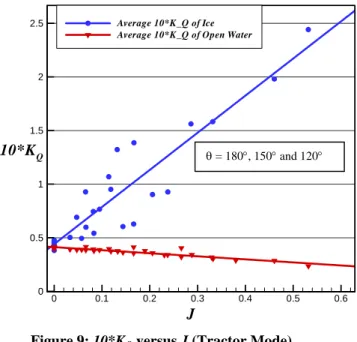
Figure 8 and figure 9 show the non-dimensional average thrust coefficient (KT) and ten times torque coefficient (10*KQ) in the tractor mode as a function of advance coefficient (J) for both pre-sawn ice and open water conditions with three different azimuthing angles: 180, 150, 120 degrees.
These figures show the ice contact resulted in increased values of the thrust and torque coefficients over open water values corresponding to advance coefficient J. Some reasons are due to the wake of the ice (blockage effects) proximity effects. The milling loads may help to increase the thrust and torque coefficient as well. If the milling loads are acting on the pressure side of the blade (Kotras et al., 1985), the thrust coefficients are increased.
wr Propeller Blade
(Face, Pressure Side)
V
T Pod housing
Figure 6: Tractor mode with 180 degrees azimuthing angle
V
wr T
Figure 7: Tractor mode with 150 degrees azimuthing angle
0 0.1 0.2 0.3 0.4 0.5 0.6 0.1 0.2 0.3 0.4 0.5 0.6 Average K_T of Ice
Average K_T of Open Water
KT
J
θ = 180°, 150° and 120°
0 0.1 0.2 0.3 0.4 0.5 0.6 0 0.5 1 1.5 2 2.5 Average 10*K_Q of Ice
Average 10*K_Q of Open Water
10*KQ
J
Figure 9: 10*KQ versus J (Tractor Mode)
Figure 10 and figure 11 show the azimuthing angle and operating condition for pusher mode. Figure 12 and Figure 13 show the non-dimensional average thrust coefficient (KT) and ten times torque coefficient (10*KQ) in the pusher mode as a function of advance coefficient (J) for both pre-sawn ice and open water conditions with three different azimuthing angles: 0, 30, 60 degrees.
In case of the pusher mode, propeller was placed behind the pod. Therefore, broken ice pieces hit the propeller blade randomly. This caused the wide range of scatter, but overall trend is similar to the open water results.
wr V
Propeller Blade (Face, Pressure Side) T
Pod housing
Figure 10: Pusher mode with 0 degree azimuthing angle
V T wr
Figure 11: Pusher mode with 30 degrees azimuthing angle
0 0.1 0.2 0.3 0.4 0.5 0.1 0.2 0.3 0.4 0.5 0.6 Average K_T of Ice Average K_T of Open Water
KT
J
θ = 180°, 150° and 120°
Figure 12: KT versus J (Pusher Mode)
0 0.1 0.2 0.3 0.4 0.5
0.5 1 1.5
Average 10*K_Q of Ice Average 10*K_Q of Open Water
10*KQ
J
Figure 13: 10*KQ versus J (Pusher Mode)
The effect of azimuthing angles on the thrust coefficient for both tractor and pusher mode is plotted in figure 14 and figure 15, in which average values are provided. As the angle from centerline of the pod was increasing, thrust coefficient values were increasing too. In figure 15, the propeller in the 60-degree of azimuthing angle for pusher mode experienced unbroken ice.
0 0.1 0.2 0.3 0.4 0.5 0.3
0.4 0.5
180 degrees Azimuthing Angle 150 degrees Azimuthing Angle 120 degrees Azimuthing Angle
J KT
Figure 14: Effect of azimuthing angle on KT for tractor
mode 0 0.2 0.4 0.6 0.1 0.2 0.3 0.4 0.5
0.6 0 degrees Azimuthing Angle
30 degrees Azimuthing Angle 60 degrees Azimuthing Angle
J KT
Figure 15: Effect of azimuthing angle on KT for pusher
mode
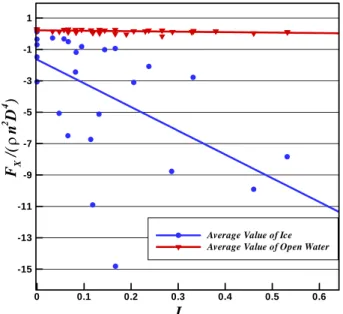
Figure 16 shows the non-dimensional global force FX as a function of the advance coefficients, and Figure 17 shows the raw data with carriage speed and RPS. The global force FX indicated the sum of the propeller wake forces and the drag (resistance) acting on the whole unit. The values of FX are scattered over a plot area, especially at a low advance coefficient region. The reason is that this plot contains three different azimuthing angles that are 180, 150 and 120 degrees for tractor mode.
0 0.1 0.2 0.3 0.4 0.5 0.6 -15 -13 -11 -9 -7 -5 -3 -1 1
Average Value of Ice Average Value of Open Water
FX /( n 2 D 4 ) J ρ
Figure 16: Non-dimensional global Fx versus J
0 20 40 60 80 -1200 -800 -400 0 400 -7 -6 -5 -4 -3 -2 -1 0 0.2 m/s 0.5 m/s R P S RPS Carriage Speed Global FX G lo bal FX (N ) Time (S)
Figure 17: Global FX, Carriage speed and RPS
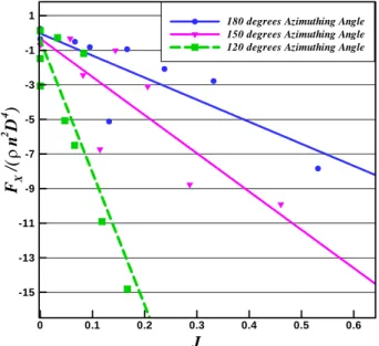
Figure 18 shows the effect of azimuthing angle on the non-dimensional global force FX. When the azimuthing angle is decreasing, the magnitude of FX is increasing. The reason is that the contact area between the pod and the ice is getting wide at the lower azimuthing angle.
0 0.1 0.2 0.3 0.4 0.5 0.6 -15 -13 -11 -9 -7 -5 -3 -1
1 180 degrees Azimuthing Angle
150 degrees Azimuthing Angle 120 degrees Azimuthing Angle
FX /( n 2 D 4 ) J ρ
Figure 18: Effect of azimuthing angle on global FX for
tractor mode
Figure 19 shows the global force FX for pre-sawn ice, pack
ice and open water simultaneously during one revolution of the propeller. Usually, the largest FX of global force was found at
the pre-sawn ice. As the pack ice, however, had its own acceleration and random direction to act on the blade, sometimes pack ice had the maximum value among them.
Number of peak is equal to the number of blade. When the propeller blades enter the ice block, loads reach the maximum value. 49.2 49.22 49.24 49.26 49.28 49.3 49.32 49.3 -200 -100 0 100 200 300 400 Pre-sawn Ice Pack Ice Open Water Blade Angular Position
G loba l F or c e FX Time [N ] A n gl e [D e gree ]
Figure 19: Global FX comparison among pre-sawn ice, pack ice and open water during one propeller revolution
Figure 20 and Figure 21 show the effect of depth of cut and propeller rotating speed on the shaft torque. As depth of cut is
higher, the shaft torque is higher. However, propeller rotating speed is higher, shaft torque is lower.
0 0.1 0.2 0.3 0.4 0.5 0.6 0.04 0.08 0.12 0.16 0.2 0.24 5 RPS, 15 mm of hi 5 RPS, 35 mm of hi KQ J
Figure 20: KQ versus J with two different depth of cut at 5 RPS 0 0.1 0.2 0.3 0.4 0.04 0.05 0.06 0.07 0.08 0.09 0.1 7 RPS, 15 mm of hi 7 RPS, 35 mm of hi KQ J
Figure 21: KQ versus J with two different depth of cut at 7 RPS
CONCLUSION
This experimental study explained the characteristics of podded propulsors in ice conditions. The design and operating criteria for ice interacted podded propulsors can be suggested. Knowledge obtained in this study can also be utilized to update regulations for ice class propellers.
ACKNOWLEDGMENTS
The study on the podded propellers is a joint project between Transport Canada and the National Research Council of Canada. Furthermore, thanks are due to Memorial University’s Technical Services Department for their help in the experimental work. Special thanks are extended to the members of the NRC- IOT for their assistance in various stages of this project.
REFERENCES
Akinturk, A., Jones, S., Rowell, B., Duffy, D. (2004), “Measuring Podded Propeller Performance in Ice”, Proceedings of the 1st International Conference on Technological Advances in Podded Propulsion, Newcastle, UK.
Jones, S. (1987), “Ice Tank Test Procedure at the Institute for Marine Dynamics”, Report No. LM-AVR-20, Institute for Ocean Technology, National Research Council of Canada.
Juurmaa, K., Mattson, T. and Wilkman G. (2001), “The Development of the New Double Acting Ships for Ice Operation”, 16th International Conference on Port and Ocean Engineering under Arctic Conditions (POAC'01), Ottawa.
Kotras, T., Humphreys, D., Baird, A., Morris, G. and Morley, G. (1985), “Determination of Propeller-Ice Milling Loads”, Proceedings of the Fourth International Offshore Mechanics and Arctic Engineering Symposium, Vol. 2, pp.336-343, Dallas.
Kron, P. and Holmstrom, L. (1999), “Hydrodynamic Aspects of Mermaid Propulsion System”, 21st Century Cruise
Ship, London/IMARE conferences and symposia, Vol. 111, No.3.
Mewis, F. (2001), “The Efficiency of Pod Propulsion”, Proceedings of the 22nd International Conference on Hydrodynamics and Aerodynamics in Marine Engineering, Bulgaria.
Moores, C. (2002), “Shaft and Blade Load Measurements on a Highly Skewed Propeller Model in Ice” Master of Engineering Thesis, Memorial University of Newfoundland, St. John's, Newfoundland.
Muller, J. (1999), “Podded Drives and Conventional Cargo Tonnage”, 21st marine propulsion conference, Athens.
Niini, M. (1995), “New Propulsion Technology for Arctic Tankers”, Shipbuilding Technology International.
Niini, M. (1997), “Azipod Propulsion Breakthrough for Large Cruise”, Cruise & Ferry, London.
Searle, S. (1999), “Ice Tank Test of a High Skewed Propeller and a Conventional Ice-Class Propeller in Four Quadrants”, Master of Engineering Thesis, Memorial University of Newfoundland, St. John's, Newfoundland.
Timco, G. (1986), “EG/AD/S: A New Type of Model Ice for Refrigerated Towing Tanks”, Cold Science and Technology, Vol. 12, pp. 175-195.
van Terwisga, T., Quadvlieg, F. and Valkhof, H. (2001), “Steerable Propulsion Units: Hydrodynamic issues and Design Consequences”, Occasion of the 80th anniversary of Schottel GmbH & Co.