Publisher’s version / Version de l'éditeur:
Vous avez des questions? Nous pouvons vous aider. Pour communiquer directement avec un auteur, consultez la
première page de la revue dans laquelle son article a été publié afin de trouver ses coordonnées. Si vous n’arrivez pas à les repérer, communiquez avec nous à PublicationsArchive-ArchivesPublications@nrc-cnrc.gc.ca.
Questions? Contact the NRC Publications Archive team at
PublicationsArchive-ArchivesPublications@nrc-cnrc.gc.ca. If you wish to email the authors directly, please see the first page of the publication for their contact information.
https://publications-cnrc.canada.ca/fra/droits
L’accès à ce site Web et l’utilisation de son contenu sont assujettis aux conditions présentées dans le site LISEZ CES CONDITIONS ATTENTIVEMENT AVANT D’UTILISER CE SITE WEB.
Canadian Acoustics, 30, September 3, pp. 32-33, 2002-10-09
READ THESE TERMS AND CONDITIONS CAREFULLY BEFORE USING THIS WEBSITE. https://nrc-publications.canada.ca/eng/copyright
NRC Publications Archive Record / Notice des Archives des publications du CNRC :
https://nrc-publications.canada.ca/eng/view/object/?id=838ed066-f464-47c8-8f49-05c7eeca39c0
https://publications-cnrc.canada.ca/fra/voir/objet/?id=838ed066-f464-47c8-8f49-05c7eeca39c0
NRC Publications Archive
Archives des publications du CNRC
This publication could be one of several versions: author’s original, accepted manuscript or the publisher’s version. / La version de cette publication peut être l’une des suivantes : la version prépublication de l’auteur, la version acceptée du manuscrit ou la version de l’éditeur.
Access and use of this website and the material on it are subject to the Terms and Conditions set forth at
Flanking transmission in wood framed multifamily dwellings
Halliwell, R. E.; Quirt, J. D.; Nightingale, T. R. T.
Flanking transmission in wood framed multifamily
dwellings
Halliwell, R.E.; Quirt, J.D.; Nightingale, T.R.T.
A version of this document is published in / Une version de ce document se trouve dans : Canadian Acoustical Association Meeting, Charlottetown, P.E.I., Oct. 9-11, 2002, pp. 1-2
www.nrc.ca/irc/ircpubs
F
LANKING
T
RANSMISSION
I
N
W
OOD
F
RAMED
M
ULTIFAMILY
D
WELLINGS
R. E. Halliwell, J. D. Quirt, and T. R. T. NightingaleNational Research Council Canada, Institute for Research in Construction Ottawa, Ontario K1A 0R6, Canada
1. INTRODUCTION
A three-year project at the National Research Council Canada to study flanking transmission in wood-framed construction under controlled conditions was recently completed [1,2]. The focus was horizontal and vertical flanking involving the wall/floor junction in multifamily buildings built to resist wind or seismic loads. This paper reports on the effect of joist orientation (relative to the wall/floor junction), junction blocking details, joist type (solid lumber vs. wood-I joists), and wall framing (double stud, single stud or single stud shear walls) for airborne excitation. The wall and floor specimens divide the test facility into four rooms (labeled A, B, C, and D in the figures). Flanking paths involving room surfaces other than those of the test specimens are negligible.
2. RESULTS
The influence of joist orientation was tested both with wood-I joists and with solid lumber joists, but the effects of joist continuity and junction details complicate the comparison. The OSB subfloor was continuous under the AB partition wall in both cases. With joists perpendicular to the partition wall, the wood-I joists were also continuous under the wall.
1 0 2 0 3 0 4 0 5 0 6 0 7 0 63 125 250 500 1 k 2k 4k Frequency, Hz TL, dB
Partition Wall - Potential Transmission Loss Direct-STC 52
Wood I-beam joists Parallel to partition wall Apparent-STC 44
Wood I-beam joists Perpendicular to partition Apparent-STC 38
Figure 1: Apparent TL between rooms A and B for the two wood-I joist orientations shown in Figure 2. The direct transmission loss through the wall construction is also shown for comparison.
It is clear from Figure 1 that the apparent TL between rooms A and B is well below the direct TL of the wall. A series of measurements with different surfaces shielded showed that the floor-floor path between rooms A and B limits the sound transmission. Clearly, flanking transmission is strongest with joists perpendicular to (and continuous under) the party
wall. In both cases, improving the party wall would not appreciably affect the apparent transmission loss.
A B
C D
A B
C D
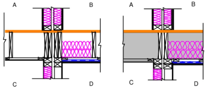
Figure 2: Floor-wall junction details with wood-I joists.
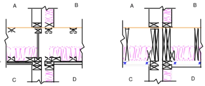
Figure 3 shows that the solid wood joists gave similar apparent TL results, for both joist orientations. Construction details are shown in Figure 4. Only the OSB was continuous across the junction, and this junction was more complex.
10 20 30 40 50 60 70 80 90 100 6 3 125 250 500 1 k 2k 4k Frequency, Hz TL, dB
Partition Wall - Potential Transmission Loss Direct-STC 67
Solid lumber joists Parallel to partition wall Apparent-STC 48 Solid lumber joists Perpendicular to partition Apparent-STC 52
Figure 3: Apparent TL between rooms A and B, for the solid wood joist constructions shown in Figure 4.
A B
C D
A B
C D
Figure 4: Floor-wall junction details with solid lumber joists.
Clearly any attempt to improve the sound isolation between rooms A and B must focus on the paths involving the floor.
This can be done either by reducing the energy getting into the floor structure, or by increasing the attenuation at the floor/wall junction. Figure 5 shows five junctions tested with the same floor (wood-I joists parallel to the wall) to assess the influence of the floor/wall junction on the flanking paths.
A B C
Shear Double
Figure 5: Sketches showing the floor-wall junction details for five variants of the double and single stud walls.
Figure 6 shows the apparent TL measured between rooms A and B, together with direct TL for these walls. In all cases the transmission is dominated by paths involving the floor, but with the more complex joint (double wall) flanking was suppressed noticeably. Single stud walls A, B, and C had essentially identical apparent TL; only case C is shown.
1 0 2 0 3 0 4 0 5 0 6 0 7 0 8 0 63 125 250 500 1 k 2k 4k Frequency, Hz TL, dB
Double stud wall
with flanking suppressed Direct-STC 55
Single stud wall C
with flanking suppressed Direct-STC 52
Single stud shear wall
with flanking suppressed Direct-STC 51
Double stud wall
Apparent-STC 48
Single stud wall C
Apparent-STC 44
Single stud shear wall
Apparent-STC 42
Figure 6: Apparent TL between rooms A and B for the double stud
wall, single stud shear wall, and single stud wall C. Also shown is
the TL expected for each wall with flanking paths suppressed.
A B
C D
A B
C D
Figure 7: Sketches showing the floor-wall junctions details for comparison of solid lumber joists and wood-I joists.
The wood-I joists commonly used in current construction are lighter than traditional solid lumber so it was of interest to consider what effect this would have on the performance of the floor/wall junction. The construction details are shown
in Figure 7. The apparent TL between rooms A and B, shown in Figure 8, is similar despite changing from wood-I to solid lumber joists. In both cases the TL is dominated by flanking paths involving the floor, in particular the floor-floor path. When viewing the changes in Figure 8 it is important to realize that changing the joist type affects three components in the transmission path - power incident on the junction, junction transmission, and radiation in the receiver room - which cannot be fully separated.
10 15 20 25 30 35 40 45 50 55 60 6 3 125 250 500 1k 2k 4 k Frequency, Hz Apparent TL, dB Wood-I joist Apparent-STC 48
Solid lumber joist
Apparent-STC 46
Figure 8: Apparent transmission loss between rooms A and B constructions using solid lumber and wood-I joists.
In the vertical direction between rooms A and C, the apparent TL showed little difference between the double and single stud walls. This is consistent with the direct path through the floor being the dominant path for vertical transmission. Joist type is not overly important for direct TL, especially when expressed as a single number rating. This is consistent with earlier findings [3]. Changes observable in the low and high frequencies for direct transmission do not correlate with those for flanking transmission (Figure 8). This suggests that joist type affects direct and flanking transmission differently.
3. CONCLUSION AND REFERENCES
A study of flanking transmission in wood frame construction has shown that for airborne excitation the floor/wall junction in multifamily buildings provides serious structural flanking when a continuous subfloor is used to provide resistance to wind or seismic loading.
1. R.E. Halliwell, J.D. Quirt, T.R.T. Nightingale, “Construction
details affecting flanking transmission in wood framed multifamily dwellings,” Proceedings INTERNOISE 2002
2. T.R.T. Nightingale, R.E. Halliwell, J.D. Quirt, “Vibration
response of floors and the effectiveness of toppings to control flanking transmission”, INTERNOISE 2002
3. A.C.C. Warnock, J.A Birta, Internal Report IRC-IR-811,
National Research Council Canada, July 2000.
This work was supported by a consortium that included Canada Mortgage and Housing, Forintek Canada, Marriott International, Owens Corning, Trus Joist, and USG.