Applications of Modular Construction Techniques for Habitability Spaces in Naval Ship Design and Production
by
Eugene R. Miller III
B.S., Naval Architecture and Marine Engineering, Webb Institute 1996 Submitted to the Department of Ocean Engineering in Partial Fulfillment of the
Requirements for the Degrees of
Master of Science in Ocean Systems Management and
Master of Science in Ocean Engineering at the
Massachusetts Institute of Technology June 1998
@ 1998 Massachusetts Institute of Technology All rights resevered
Signature of Author... ... ... / Department of Ocean Engineering
May 8, 1998 Certified by... .... ... ... enry S. Marcus
NAVSEA Professor of Ship Acquisition Thesis Supervisor Certified by ...
Senior Lec
Accepted by...
/ -Alan J. Brown
turer, Naval Architecture and Marine Engineering Thesis Supervisor
MASSACHUSETTS INSTITUTE Departme
OF TECHNOLOGY Department
CT 2 3 1998
LIBRARIES
Kim Vandiver mt Graduate Committe of Ocean EngineeringApplications of Modular Construction Techniques for Habitability Spaces in Naval Ship Design and Production
by
Eugene R. Miller III
Submitted to the Department of Ocean Engineering on May 8. 1998 in Partial Fulfillment of the requirements for the Degrees of Master of Science in Ocean Systems Management and Master of Science in
Ocean Engineering ABSTRACT
Traditional construction methods for habitability spaces in naval ships, particularly aircraft carriers, are manpower intensive and expensive. In response to decreasing defense spending, the Navy is considering methods to improve the affordability of aircraft carriers. Modular construction techniques for habitability spaces offer potential costs savings.
Although cruise ship builders have utilized modular construction techniques for almost 30 years, these modules do not meet Navy survivability requirements. The Navy's Affordability Through Commonality (ATC) program is developing new joiner bulkhead
systems and modular sanitary spaces to meet Navy performance requirements. However, very little is known about the cost benefits and area and weight penalties for using
habitability modules in aircraft carriers.
An arrangement design project was carried out on a new aircraft carrier design to quantify the cost, area, and weight benefits and penalties for using modular habitability spaces. With the assumptions made in this research, the results show that modular habitability spaces offer a 15 percent cost benefit, but suffer a 7-15 percent area penalty and 8-13 percent weight penalty. A plan for testing modular construction techniques on a new aircraft carrier is also presented. While modular construction techniques have many benefits in cruise ships, the benefits for aircraft carriers are more limited, and depend on the characteristics of the individual design.
Thesis Supervisor: Henry S. Marcus
Title: NAVSEA Professor of Ship Acquisition Thesis Supervisor: Alan J. Brown
ACKNOWLEDGEMENTS
I would like to thank Professor Marcus for going above and beyond to provide support and guidance over the last two years. I would also like to thank Dr. Brown for taking the time to serve as a thesis supervisor. In addition, I would like to thank the Naval Sea Systems command for providing financial support for this project.
I would also like to thank Andy and Doug for helping establish the Cambridge branch of Webb Institute, and keeping things interesting. Of course, I would like to thank Heidi
TABLE OF CONTENTS:
1.0 INTRODUCTION
2.0 REQUIREMENTS FOR THE CONSTRUCTION OF HABITABILITY SPACES ON NAVAL SHIPS
2.1 Specifications for Construction of Nonstructural Bulkheads 2.1.1 Definitions 2.1.2 General 2.1.3 Joiner Bulkheads 2.1.4 Coamings 2.1.4.1 Non-Watertight Coamings 2.1.4.2 Semi-Watertight Coamings 2.1.4.3 Watertight Coamings 2.1.5 Intermittent Welding 2.1.6 Overheads 2.1.7 Shock
2.2 Construction of Habitability Spaces
2.3 Specifications for Construction of Sanitary Spaces 2.3.1 Materials
2.3.2 Erection 2.3.3 Ceilings
2.3.4 System Hookup 2.3.5 Access
2.3.6 Emergency Wash Facilities 2.3.7 Shock
2.3.8 Others
2.4 Construction of Sanitary Spaces
2.5 Assessment of Current Habitability Space Specifications 3.0 AIRCRAFT CARRIER CONSTRUCTION
3.1 Nimitz Class Aircraft Carriers
3.2 Newport News Shipbuilding, Inc. 3.3 Habitability Spaces in Aircraft Carriers 3.4 Carrier Arrangement Design Hierarchy 3.5 Layout of Habitability Spaces
3.5.1 Gallery Deck 3.5.2 02 Deck 3.5.3 01 Deck 3.5.4 Main Deck 3.5.5 Second Deck 3.5.6 Third Deck
3.5.7 Other Considerations in Habitability Space Design 3.6 Aircraft Carrier Construction Schedule
3.7 Construction of Habitability Spaces 3.7.1 Reasons for On-Ship Outfitting
3.7.1.1 Critical Path 44
3.7.1.2 Dry-Dock Limitations 44
3.7.1.3 Flexibility 44
3.7.2 Habitability Space Construction Method 45 3.8 Assessment of Current Habitability Construction Methods 51 3.9 Opportunities From Newport News Commercial Shipbuilding 53
3.10 Conclusions 54
4.0 NAVY PROGRAMS TO IMPROVE THE CONSTRUCTION OF
HABITABILITY SPACES 56
4.1 Affordability Through Commonality Program 56
4.1.1 ATC Approach to Modularity 56
4.1.2 ATC Advantages of Modularity 58
4.1.2.1 Design 58
4.1.2.2 Arrangements 58
4.1.2.3 Fabrication 59
4.1.2.4 Construction 59
4.1.2.5 Logistics 59
4.1.3 ATC Module Development 59
4.2 Modular Crew Sanitary Space 60
4.2.1 Modular Sanitary Space Development 60 4.2.2 Modular Crew Sanitary Space Applications 63
4.3 Integrated Joiner Bulkhead System 64
4.3.1 Motivation For IJBS 64
4.3.2 IJBS Design 65
4.3.3 IJBS Installation 66
4.3.4 IJBS Assessment 69
4.3.5 IJBS Program Status 71
5.0 CRUISE SHIP CONSTRUCTION 72
5.1 Introduction - The Cruise Ship Industry 72
5.2 Kvaerner Masa-Yards 73
5.3 Cruise Ship Design Method 74
5.4 Layout of Habitability Spaces 75
5.5 Modular Cabins 76
5.5.1 Motivation for Modular Cabins 76
5.5.2 Modular Accommodation Based Development Schedule 77
5.5.3 Module Design and Mock-Up 78
5.5.4 Module Construction 79
5.5.5 Module Transportation 82
5.5.6 Installation on Ship 83
5.5.7 Module Design and Installation for Restricted Areas 86
5.5.8 Reconfigurability 86
5.6 Advantages of Modular Accommodation Systems 86
6.0 EVALUATION OF MODULAR HABITABILITY SPACES IN NEW
AIRCRAFT CARRIER DESIGNS 89
6.1 Ship Design 89
6.2 Habitability Space Arrangement 92
6.3 Module Design 93
6.4 Structural Allowances 95
6.5 Passageway and Overhead Clearance 96
6.6 Module Arrangement 96
6.7 Distributive Systems 99
6.8 Transportation and Production 101
6.9 Module Installation 102 6.10 Evaluation 105 6.10.1 Arrangement Efficiency 105 6.10.2 Weight 108 6.10.3 Cost 110 6.11 Commercial Substitution 114 6.12 Conclusions 117
7.0 COMPARISON AND ASSESSMENT OF MODULAR HABITABILITY
SPACES IN NEW DESIGN AIRCRAFT CARRIERS AND CRUISE SHIPS 119
7.1 Design and Production 119
7.1.1 Arrangement Process 119
7.1.2 Installation Stage and Construction Sequence 122
7.1.3 Producibility/Work on Ship 125
7.1.4 Material Ordering Time 127
7.2 In Service 128
7.2.1 Human Engineering 128
7.2.2 Safety/Survivability 129
7.2.3 Maintenance and Reconfigurability 130
7.3 Weight 132
7.4 Cost 133
7.5 Conclusions 134
8.0 EVALUATING THE EFFECTS OF MODULAR HABITABILITY SPACES
ON TOTAL SHIP DESIGN 138
8.1 How To Do This Evaluation 138
8.2 Possible Outcomes 139
9.0 INCORPORATING MODULAR CONSTRUCTION TECHNIQUES INTO CURRENT AIRCRAFT CARRIERS AND OTHER NAVAL SHIPS 141
9.1 Testing Program 141
9.2 Testing Objectives 142
9.3 Test Plan 143
9.4 Test Restrictions 143
9.5 Potential Test Spaces 144
9.7 Test Program Schedule 148
9.8 Distributive Systems 148
9.9 Test Program Conclusions 149
9.10 Other Possible Applications for Habitability Modules 149
9.10.1 Amphibious Assault Ships 149
9.10.2 Other Amphibious Ships 150
9.10.3 Surface Combatants 151
9.10.4 Hospital Ships 152
9.11 Conclusions 152
10.0 CONCLUSIONS 153
APPENDIX A: Section 621 LPD-17 Ship Specification Al APPENDIX B: Section 644 LPD-17 Ship Specification B1 APPENDIX C: Weight Estimate of Navy Module, IJBS, and
LIST OF FIGURES: Figure 2-1 Figure 3-1 Figure 3-2 Figure 3-3 Figure 3-4 Figure 3-5 Figure 3-6 Figure 3-7 Figure 3-8 Figure 3-9 Figure 3-10 Figure 3-11 Figure 3-12 Figure 3-13 Figure 3-14 Figure 3-15 Figure 3-16 Figure 4-1 Figure 4-2 Figure 4-3 Figure 4-4 Figure 4-5 Figure 4-6 Figure 5-1 Figure 5-2 Figure 5-3 Figure 5-4 Figure 5-5 Figure 5-6 Figure 5-7 Figure 5-8 Figure 5-9 Figure 5-10 Figure 5-11 Figure 6-1 Figure 6-2 Figure 6-3 Figure 6-4 Figure 6-5 Figure 6-6
Current Joiner Bulkhead Design
Nimitz Class Aircraft Carrier
Aircraft Carrier Arrangement Hierarchy Gallery Deck Arrangement
02 Deck Arrangement 01 Deck Arrangement Main Deck Arrangement Second Deck Arrangement Third Deck Arrangement
Typical Aircraft Carrier Construction Schedule Compartment Turnover Schedule
Crew Berthing Space With Furniture Foundations Laid Completed Crew Berthing Space
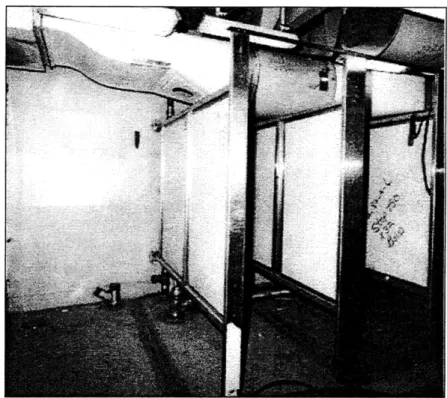
Officer Stateroom Under Construction
Intermix of Function of Crew Recreational Spaces Sanitary Space Under Construction
Completed Sanitary Space ATC Panelized Head Concept MCSS "Clean" Side
MCSS "Dirty" Side Redesigned MCSS
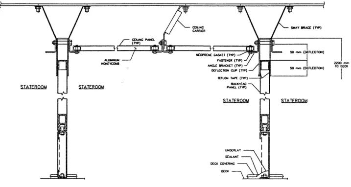
IJBS Coaming, Panel and Deflection Joint IJBS Ceiling System
Fantasy Class Cruise Ship
Passenger Deck Layout on Fantasy
Traditional Cruise Ship Construction Schedule
Modular Cabin Based Cruise Ship Construction Schedule Typical Offshore Crew Module Layout
Cabin Wall Panel Section Panel Joining Method
Module System Connection Points Lifting a Module
Close up of Lifting Dolly
Arrangement of Lifting Dollies on Module
CVX Concept Design Used For Modular Habitability Space Study
Notional Officer Module For CVX Concept Design Structural Allowances in Forward Officer Berthing Compartments
Arrangement of Forward Officer Berthing Compartments, 01 to Third Deck
Arrangement of Forward Officer Berthing Compartments, Fourth and Fifth Deck, Sections A-A and B-B
Zonal Electrical Distributive System
19 28 33 35 36 37 38 39 40 42 43 46 47 48 49 50 50 61 62 62 63 68 68 73 76 77 78 79 80 81 82 83 84 85 98 100
Zonal Piping and HVAC Distributive Systems "Blue Sky" Method of Module Installation
Side Installation Method for Habitability Modules Construction Sequence For Cruise Ships With Modules Potential Module Installation Test Area
Figure 6-7 Figure 6-8 Figure 6-9 Figure 7-1 Figure 9-1 100 103 103 124 145
LIST OF TABLES:
Table 2-1 Summary of Sanitary Space and Crew Living Space
Specifications 27
Table 3-1 Aircraft Carrier Crew Breakdown 30
Table 6-1 Aircraft Carrier Comparison 90
Table 6-2 Arrangement Efficiency Percentage Calculations 106 Table 6-3 Summary of Weight Penalties for Using Modules 109 Table 6-4 Cost Comparison of Alternative Outfitting Methods 113 Table 6-5 Cost Comparison of Alternative Outfitting Methods Using
On-Block Outfitting 113
Table 6-6 Weight Impacts of Commercial Module Substitution 115 Table 6-7 Cost Impacts of Commercial Module Substitution 116 Table 7-1 Summary of Advantages and Disadvantages of Modular
Habitability Spaces in Cruise Ships and Aircraft Carriers 136 Table 8-1 System Impact on Total Ship Design, Officer Berthing Spaces
Important 139
Table 8-2 System Impact on Total Ship Design, Officer Berthing Spaces
Unimportant 140
1.0 Introduction
Today's Navy is facing many new challenges. Although the cold war is over, the U.S. Navy must continue to meet commitments around the world. Since the end of the cold war in 1988, the U.S. Navy has been called upon for a variety of missions. These include traditional forward presence and diplomacy missions, actual combat operations,
peacekeeping, and humanitarian missions.
For all of these missions, the Navy relies on the power and flexibility of aircraft carriers. Whenever there is a global crisis, the U.S. relies on carrier battle groups to represent the nation's interests. The Nimitz class aircraft carriers form the backbone of the current carrier fleet. At over 1,000 feet in length, these nuclear powered ships are the largest naval ships ever built. With an airwing of over 85 aircraft, they have incredible power and flexibility.
While the need to keep forces around the world is as important as ever, it is not possible to continue to maintain defense spending at past levels. And the power of the aircraft carrier does not come without a price. A new Nimitz class aircraft carrier costs over 4 billion dollars, without aircraft. Over the 50 year life of the carrier, life cycle costs will come to another 15 billion. Considering the tremendous cost of aircraft carriers and shrinking budgets, it is extremely important to identify ways to improve affordability in . future carriers.
One method for improving affordability is to increase common elements between
different ship classes. This is the goal of the Navy's Affordability Through Commonality (ATC) project. By designing a range of standard modules, the ATC group hopes to reduce design and construction costs. In addition, improved standardization will reduce crew training and maintenance costs. Among the ideas the ATC group is investigating are habitability modules. Habitability modules include sanitary spaces and berthing quarters. To date, the ATC group has developed a prototype of a modular crew sanitary space, which it is planning to install on the new LPD-17 amphibious ship.
The idea of habitability modules is not new. Kvaemer Masa-Yards, a world leading commercial shipbuilder in Finland, has used modular cabins in its cruise ships for many years. By building modular cabins off the ship, they can begin outfitting work earlier in the construction process. In addition, building the cabins in a specialized factory is quicker and less expensive than assembling them on the ship. The cabins are sent to the shipyard as completed units and inserted into the ship at the outfitting pier. Kvaemer claims they have reduced their outfitting expenses almost 50% by switching to modular cabins.1
In some ways, aircraft carriers have much in common with cruise ships. Modem cruise ships displace over 70,000 tons - almost as much as a nuclear powered aircraft carrier. In addition, cruise ships must provide magnificent food and accommodations for up to 3,000 passengers. All of these requirements force cruise ships to devote large areas to cabins and restaurants. Aircraft carriers are also extremely manpower intensive, requiring over 6,000 crew members. While the comfort level is different, many of the fundamental berthing, sanitary, and messing requirements are similar. If modular habitability spaces have cut costs in the cruise ship business, is it possible they will also make aircraft carriers more affordable?
Just as there are similarities, there are huge differences. An aircraft carrier's primary mission is to operate aircraft. As a combatant, an aircraft carrier must also be able to survive damage and continue to operate. Several questions must be addressed to accurately evaluate the application of modular construction techniques for habitability spaces in an aircraft carrier. To answer these questions, it is first necessary to outline the requirements for the construction of habitability spaces on a naval ship. The
requirements for nonstructural bulkheads and sanitary spaces are found in the U.S. Navy
General Specifications, sections 621 and 644 respectively. These sections outline
Bosworth, Michael and Hough, Jeffrey, "Improvements in Ship Affordability." SNAME Transactions, Vol. 101, September 1993.
material selection, design, and shock and fire resistance characteristics for habitability spaces.
It is also important to examine current habitability construction methods. Currently, habitability spaces are "stick built" on board the carrier at the outfitting pier. This method is well known, but expensive. Even using preoutfitting - doing outfitting work on-block - can significantly reduce labor costs. It is necessary to identify why the work is done on-ship, and what physical and scheduling limitations could affect modular
construction techniques.
After examining the advantages and disadvantages of current outfitting methods, it is possible to evaluate alternative construction methods. The ATC program is developing a new joiner bulkhead system. While this system does not use self supporting modules, it incorporates producibility improvements designed to reduce costs. In addition to Navy
efforts, it is useful to examine commercial modular habitability systems. The ATC program is relatively young, while Kvaerner has been building modules for almost thirty years. The more experienced commercial sector may have some valuable lessons for the Navy.
Because habitability modules are a new concept in the Navy, very little is known about the relative trade-offs. It is expected that modules will carry weight and area penalties, while potential cost benefits are unknown. Advantages in commercial shipbuilding do not always carry over to the naval shipbuilding process. For example, cruise ships have large, uninterrupted decks for passenger cabins. As a result, modular cabins fit into the available space without significant area penalties. However, habitability spaces on naval ships are often located in unusual locations which are not well suited for modules. Using modular habitability spaces in these compartments leaves unused area. But this area penalty has never been quantified. Weight penalties and cost benefits are also unknown.
To answer these questions, modular habitability spaces are integrated into a concept design of the Navy's next aircraft carrier, the CVX. The concept design was developed
by third year students in the Naval Ship Construction and Engineering program at MIT. This design project focuses on the officer berthing spaces in the CVX design, and presents a methodology for quantifying the weight and area penalties, as well as cost benefits of modular construction techniques. The impact of system design on total ship design and effectiveness is also examined.
After examining the integration of modular construction techniques into a new design, a plan is presented for testing modular installation techniques in a small area on CVN-77, the last Nimitz class carrier. The test program is necessary to establish the technical feasibility of modular construction techniques for aircraft carriers before full scale installation in a new carrier. Finally, the application of modular habitability spaces in other types of naval ships is examined. Although aircraft carriers are the best suited to modular construction techniques because of their physical dimensions and large crew size, several other naval ship types could also benefit.
2.0 Requirements for the Construction of Habitability Spaces on Naval Ships
Naval vessels are among the most complex machines in the world, with millions of parts. On a one for one basis, U.S. Navy vessels are generally acknowledged as the most
technologically advanced and capable warships in the world. However, building vessels to these high standards requires a rigorous design and construction process. The
construction of U.S. Navy vessels is governed by a comprehensive set of requirements, evolved and developed over a long period of time. These requirements are based on years of in-service experience, and are intended to insure the high quality and
survivability of U.S. ships. While these specifications might seem overly burdensome compared to commercial shipbuilding requirements, they were originally developed for specific performance-based reasons. It is, therefore, necessary to fully review and understand these requirements before considering alternative methods.
The construction of habitability spaces in U.S. Navy ships is governed by the General
Specifications for Ships of the US. Navy. There are separate sets of specifications for
joiner bulkheads and sanitary spaces. Joiner bulkhead requirements are found in Section 621, Nonstructural Bulkheads and Partitions. Sanitary space requirements are found in Section 644, Sanitary Spaces and Plumbing Fixtures and Fittings.
2.1 Specifications for Construction of Nonstructural Bulkheads
Each ship class has its own ship specifications, based on the general specifications. The LPD-17 specification, Section 621, is representative of nonstructural bulkhead
requirements and is presented here for several reasons. The LPD-17 is the newest ship class in the U.S. Navy, and its specifications reflect the most recent thoughts on
nonstructural bulkhead requirements. (Section 621 of the LPD-17 specification is dated April 1996.) It is anticipated the LPD-17 specifications will be representative for a range
of future naval vessels. A summary of the specification is presented here, and the complete specification is found in Appendix A.
Summary of Nonstructural Bulkhead and Partition Requirements for LPD-17
2.1.1 Definitions
Nonstructural bulkheads are bulkheads which do not contribute directly to the strength of the hull and do not support decks.
2.1.2 General
Nonstructural bulkheads are of three general types: joiner bulkheads, expanded metal bulkheads, and non-load bearing lightweight plate. Bulkheads for bounding and
subdividing such spaces as offices, passages, quarters, foodservice spaces, pantries, and medical and dental spaces shall be joiner type.
Nonstructural bulkheads attached to portions of decks subject to helicopter landing or vehicle and forklift motion and all joiner bulkheads shall have a rattle proof deflection joint along the top edge to permit deck vertical deflection of+- 50 mm without damage to
the bulkhead.
Nonstructural bulkheads shall be stiffened locally in way of furniture and other articles supported from or attached to the bulkheads as required. Where equipment is mounted on nonstructural bulkheads, the analysis of design loads shall consider ship motion factors.
2.1.3 Joiner Bulkheads
Joiner bulkheads shall be GRP/NOMEX, non-filled, sandwich constructed panels. The GRP/NOMEX honeycomb panel consists of a paintable phenolic resin impregnated fiberglass face sheet over an aramid fiber honeycomb core. The honeycomb core dimension shall be 6 mm hexagonal shaped cell size with a core density of 50 kg/m3.
Overall panel thickness shall be 15.88 mm, including the decorative face sheets. Where decorative sheathing is required, face sheathing shall be 0.68 to 0.94 mm thick High Pressure Plastic Laminate (HPPL) or stainless steel (CRES 304), and meet fire performance standards of CRD-104.
Bottom edge joints in dry spaces shall be sealed with a commercial quality, all-purpose, paintable adhesive/caulking compound. Bottom and vertical edge joints in wet spaces shall be sealed with silicone sealant AMS 3362. Where acoustic or thermal insulation is required, the insulation shall be attached to the bulkhead and the HPPL finished material shall be omitted.
If possible, joiner bulkheads shall be located in line with stanchions. Construction of bulkheads which separate air conditioned from non-air conditioned areas shall be of fume-tight construction. Bulkheads of darkrooms, staterooms, and the Quiet Room and similar spaces shall be constructed so as to exclude light.
2.1.4 Coamings
Coamings shall be 150 mm high, 5 mm thick steel, ASTM A36, painted, and of non-watertight construction. Watertight coamings shall be installed between adjoining wet spaces. Coamings for nonstructural bulkheads shall also be of semi-watertight
construction when bounding a space likely to have water or oil upon the deck, when used to protect stores or deck equipment against mop or water leakage from adjoining spaces where liquids are stowed for operating mechanical systems, or when provided for rat-proofing. Tightness classifications and welding requirements are as follows:
2.1.4.1 Non-watertight coaming
Where a coaming serves as a boundary between adjoining dry spaces, the coaming shall be intermittently welded on both sides when making connections to the deck and the vertical structure at the end of the coaming.
2.1.4.2 Semi-Watertight Coaming
Where a coaming serves as a boundary between a wet space and a dry space, the coaming shall be continuously welded on the wet side boundary and intermittently welded on the dry side.
2.1.4.3 Watertight Coaming
Where a coaming serves as a boundary between adjoining wet spaces, the coaming shall be continuously welded on both sides.
2.1.5 Intermittent Welding
As a minimum, intermittent welding shall consist of a bead of weld 25 mm long, with adjacent beads spaced not greater than 150 mm apart.
2.1.6 Overheads
In addition to the requirements for nonstructural bulkheads in section 621, section 637 specifies which areas are to receive overhead sheathing. Currently, staterooms and offices are not scheduled to receive overhead sheathing. In all applications, sheathing
shall be installed in a manner which will not impede damage control efforts. Full visibility and accessibility shall be provided for damage control fittings and other vital system components requiring access for inspection, maintenance, and operation.
Installation of overhead sheathing for humidity control and protection of insulation shall be provided in shower and shower drying areas. Installation for aesthetic purposes shall be confined to Flag and Commanding officer quarters, quarters of officers or equivalent rank, Executive officer quarters, chapels, wardroom messrooms, CPO messrooms, and lounges.
2.1.7 Shock
Although shock requirements are not outlined in section 621, all joiner bulkheads must meet grade B shock requirements. Grade B shock qualification allows for loss of function, but requires equipment not come adrift. In addition, all furniture in spaces which will be occupied during general quarters (marine berthing compartments) must also meet grade B shock requirements.
2.2 Construction of Habitability Spaces
There are three types of joiner bulkheads: extruded bulkheads, honeycomb bulkheads, and stiffened sheet metal bulkheads. There are NAVSHIP detailed drawings for each of these joiner bulkhead types. The general construction and installation procedure and
details are summarized here. Figure 2-1 illustrates current joiner bulkhead designs.
Extruded and Honeycomb bulkhead systems use a 6 inch (150 mm) flat bar coaming welded directly to the deck. There is either a Z-clip or H-clip attached near the top of the coaming. The joiner bulkhead panel rests either between the Z-clip and the coaming or inside the H-clip, and is fastened to the coaming. An alternative coaming system utilizes a U-channel welded directly to the deck. The joiner panel is inserted into the channel and fastened. Stiffened sheet metal joiner bulkheads are fastened directly to a 6 inch flat bar coaming, without Z or H-clips.
Curtain plates are used to form the upper boundary of a compartment and are usually 30 inches high with gussets attached 24 inches center to center. Curtain plates are secured by welding them to the underside of the overhead deck. If the curtain plate is attached to the underside of a structural member, additional stiffness is provided by welding an angle bracket to the curtain plate. Curtain plate must conform to the tightness requirements for the particular space (i.e. fume-tight, light tight, etc). This is more difficult, since a curtain plate is penetrated by pipes, cableways, and HVAC ducts and notched in way of
stiffeners. All curtain plate penetrations must be sealed to meet particular tightness requirements.
Installation of both coamings and curtain plate begins by scribing the piece to fit the installation location. After scribing, the coamings or curtain plate are cut to fit along the structure, leveled, and welded to the structure. Once in place, the curtain plate obstructs the installation of piping, HVAC, and electrical subsystems. Each penetration requires a unique seal to maintain the integrity of the compartment. Installing curtain plate is even more difficult if the subsystems are already in place, and the plate must be installed
(D -WEIGHT IABL
,TC It7Ilio4sovolAo wIM AI UN IPlOMPLSS l
691 ALUMINM. 41U409.$ - PC R101 te) IN Mt-t pi- RL. 9.m 6 n 4.nuu~n l 1
=t iiiii. STCCL l C."me ttot 1 it's Lat
c 90 0 w LC0 He 4 0 0 #0 041l*0 ow 00
NOR "a DOCUII IRIANr~r Mil NG NS16601 k
r Ii C) C-0 CI (P rIQ . S& =nL 'NOTES ()
*09"SPALOMOCA W.1. @Qd VIA&" b404a.0 40.w044S.
1 49100994%2 04001""." 4 W 0 . -ON MS4"""09049011.
6900.1094" AS&. 90.4 0A%9'49 9 09.P& 0 9900 C4 414 Acl. . .
IWI0 poo090 0 0 it9 950.00. 1 4 1-90040 1.99 004 6. V .it.0 "I 4009909 0.4*00999001044000440 9W 000 & .Ot% .0 1 W A yftv to A&% ITS.O." 0"t" *1 U-M .U.'V#* 04.14. l
949494990WO9P046990,999.06900ft9.V0I9MUNI 049099901 . 1.9 1006,19 soMlNV0.410.A&a W46 S0 99 9900 I 09Gf9 40AN19 1.4 %Is"$ 0USOMIFI 99 9 WA0OW0A4IA&
44 " 1- V-. t nlmosallpe GI*, 6104"41 nos 24' -.Alp go5 ~ As 14A049o90.4.4004494 0.00 990 Os 41590 09400 *0911 W 41.0n~,990 00009.0( 0400499 1.10 094990lu 0' r~*l~mOtolaCI: log 0044049 900cr~) r 9094.90090 99459 .. 199199099449009009 00900999 U0 904A ,900 0L o 90.099,0990909990009094099 0099440000000004 0409904904 0449991904049014400099.49994000009409 0410009.4r . 0449,H~*: 900 109 999.4994 9440 990.0.999' 00 r ~ r 09 94449 9ul
4404 00094991O I~ (LI1 I~ l*1II(~ 1 ) l
A. 4409499909 II 091409.014.99.4191llr ,~ sru~ ~
99 11190. 904.0. 0MA- 4094-0.1009*.9.
i oi&LfU ~6IIRto9w ti.ID.DL.SCL
4 909.4o4 0.10 L..J0 4I9fl9.v-004014901 49449 . wt0 *Sir&049 I ,: ,4; w " !1-! IAGS0.10 2.1 114199090440J im 40%3.14009 COW so 04.491 64 R i 9 94 009 1999 -1I-16I.%%IA 9000 IU~rr Ib4044 ~u
It..40i0J9 90599994.UA0 ) L 01Or MAL_~ICR9I..
iI10..01009.00L4WJFl )-LW
alp# o 11.11A.1 I-, 9o*4.5~*9' MTALJO4lMAKR~AD. NAVAk S14,
106 ww" as sot000*L D IACCO*(ATOUO ~ oIS TMS COMOAA 194 04, .49-6..1 0400 904900999 9944 09 1 "~.j tui L,.: r~~ ar rir I...i."L11' t- I I 090 1 4L1K.L4 adIt #.fJ7
I
9LII~L
A' ~~~L.4. .MiJL~ .9.190Th 3f~~j4.$ iOPII 9b.lkLs.10.l044 _ _ _ f I _ ___ _ _ __II_ __ _I - ---- -" A" ,,(,-v f== t -irT11=112around existing systems. While installing coamings requires on-ship welding, installing curtain plate is worse, as it requires time-consuming overhead welding.2
Panel installation is facilitated by riveting Z or H-clips to the top of the coamings. Because of requirements to accommodate relative motion between decks, deflection joints are installed at the panel's upper connection points. For extruded and honeycomb joiner bulkhead panels, the deflection joint is composed of a Z-clip riveted directly to the
curtain plate. The bottom of the joiner panel rests in the clip on the coaming, and the panel's upper edge floats between the Z-clip and the curtain plate. If the joiner panel does not require a deflection joint, a Z-clip is still used, but the panel is riveted to the clip and curtain plate. Stiffened sheet metal bulkheads not requiring deflection joints are riveted directly to the coaming and curtain plate.
For honeycomb bulkheads, panel to panel connection is accomplished with an H-post. The panel ends slide into the H post and are fastened to the post. Honeycomb panels are attached to structural bulkheads with a U-channel. The U channel is welded to the structural bulkhead, and the panel end slides into the U channel and is fastened. Intersecting honeycomb panels use either a U channel or a T post. The U channel is fasten perpendicularly to one panel. The other panel end slides into the U channel and is fastened. Corners are built using a rounded 90 degree corner post that fastens to both panels.
Extruded bulkhead panels are fastened to each other using a joiner tube. Each panel slides over half of the joiner tube, and is riveted in place. Panel intersections are built by attaching a U channel to the side of one panel, and sliding the other panel over the U-tube. A T-intersection extrusion is used at the intersection of three extruded panels.
Stiffened sheet metal panels are fastened together by folding both ends of each sheet to form channels. The channels are then fastened together. Alternatively, one end of the
2 NAVSEA 03R & NAVSEA 03H, "Affordability Through Commonality (ATC) Furniture Standardization
panel can be folded into an L shape. The channel end of one panel is then fastened to the L-end of the adjacent panel.
Currently, joiner bulkhead panels are manufactured in standard sizes. Ship outfitters must cut and fit joiner bulkhead panels in the field to meet individual compartment dimensions.
Furniture installation is a major part of habitability space construction. While the installation process varies for different types of furniture, it follows this general process. The foundation is scribed to fit the installation location, cut, leveled, and welded to the deck. Each type of furniture has a unique foundation, and can only be used with that furniture piece. Flashing is also installed around each piece of furniture for rat-proofing purposes. Furniture is then brought to the space in kit form, and assembled in place on the foundation.
2.3 Specifications for Construction of Sanitary Spaces
The LPD-17 specification, Section 644, is representative of sanitary space requirements for future U.S. Naval vessels and is presented here. (Section 644 of the LPD-17
specification is dated March 1996) The specification was written after the Affordability Through Commonality program was developed and takes into account some of those lessons. (See Chapter 4) A summary of the specification is presented here, and the complete specification is found in Appendix B.
Summary of Sanitary Space Requirements for LPD-17
2.3.1 Materials
The sanitary space bulkhead panels and partitions are to be constructed of 1.27 mm thick CRES formed flush panels. The bulkhead panels shall be supported by a CRES
framework. The individual panels and partitions shall be removable in a non-progressive manner from the inside of the sanitary space. Where exposed to view, the outside of the
sanitary spaces shall have flush finished panels. The material and finish of exterior panels is in accordance with the adjacent space. These panels are not required where the sanitary space boundary abuts ship structure or another sanitary space.
2.3.2 Erection
Sanitary space erection and attachment of components and accessories shall be by Huck bolts, CRES machine screws or bolts with nuts or press nuts as applicable. Components and accessories shall be mounted and fully supported by bulkhead panels, framework, or partitions. Panels shall be reinforced or doubled in way of fittings. Panel joints shall be sealed by neoprene gaskets.
2.3.3 Ceilings
Ceilings shall be provided. Panels shall be CRES or aluminum, progressively interlocking and rattle free. The first and last panel shall be fixed into position by
machine threaded captive fasteners. Ceiling panels shall be removable from the inside of the sanitary space. The underside of the ceiling shall be not less than 2.0 m from the steel
deck. Curtain plates and fascia plates shall be provided separately or in combination, as needed, to separate the volume above the sanitary space from adjacent spaces.
2.3.4 System Hookup
Ventilation and Electrical systems serving the sanitary space shall be installed behind the bulkhead panels and above the ceiling panels. Within the space, piping systems for potable water, vacuum waste collection, and lavatory plumbing drains and vents shall be grouped to minimize the number of connections to the ship's systems and concealed behind removable bulkheads and ceiling panels.
2.3.5 Access
Access panels shall be provided for access to systems serving the sanitary space for inspection, maintenance and repair. Quick-acting hinged access panels shall be provided for access to damage control fittings which are concealed by the bulkhead panels or ceiling.
2.3.6 Emergency Wash Facilities
Includes eye/face and deluge shower eye/face units. The specification outlines which spaces must have these units, maximum and minimum water pressures, alarms, and information labels.
2.3.7 Shock
Joiner bulkheads and panels surrounding troop, troop officer, and SNCO sanitary spaces shall meet grade B shock requirements.
2.3.8 Other
Section 644 also provides dimensional requirements for showers, combined shower and drying areas, water-closets, and lavatories. Locations for latches, hooks, ventilation terminals, and lights are also specified. Drinking water coolers are covered in section 644d. The location and makes of fixtures and fittings is also shown.
2.4 Construction of Sanitary Spaces
Sanitary spaces have traditionally been built in much the same manner as other living spaces. The biggest differences were the additional piping runs required for the plumbing fixtures and the different panel facing material (CRES). Actual installation of joiner bulkheads was done in the same manner as for other living spaces as described above. However, the LPD-17 specifications for sanitary spaces were developed after the
Affordability Through Commonality program developed a Modular Crew Sanitary Space (MCSS). The MCSS concept is intended to minimize on ship outfitting time through the use of standard, preoutfitted panels. The LPD-17 specifications referenced here reflect the lessons learned and recommendations of this program. While the specification reflects these production considerations, it still reflects the original performance-based requirements.
2.5 Assessment of Current Habitability Space Specifications
The specifications for nonstructural bulkheads for crew living spaces reflect a different approach than the specifications for the sanitary spaces. While the two specifications do not have conflicting requirements, it is also apparent the sanitary space specifications were designed to coincide with modular construction techniques. For example, while the MCSS requirements specified panels must be removable in a non progressive manner, that issue was not addressed in the nonstructural bulkhead section. Traditional joiner bulkhead systems do not use standardized panel widths, and are not designed for easy removal. In addition, there are no requirements for quick action access panels for damage control fittings in the nonstructural bulkhead specification. Nevertheless, by examining the similarities of the two specifications, it is still possible to summarize the vital requirements for habitability spaces.
Within the two specifications, a few items merit emphasis. The sanitary space specification requires individual panels and partitions must be removable in a non-progressive manner from inside the module. This is necessary to allow for easy
maintenance, inspection, and damage control without taking down all the panels to access the desired area. Also important is the requirement for fixtures and components to be mounted and fully supported by bulkhead panels, framework, or partitions, as opposed to deck mounting. While this increases the complexity of the panel mounting system, it has several advantages. This arrangement supports both pre-outfitted panel construction methods as well as full modular construction. In addition, it is anticipated that a panel mounted fixture able to move with the panel under load or shock will be more resistant to damage.
Nonstructural bulkhead requirements for other habitability spaces do not specify standardized panel sizes or require bulkhead mounted furniture. However, just as the sanitary space specification require CRES faced panels, the nonstructural bulkhead specification requires HPPL or CRES facing. In addition, 50 kg/m3 low density GRP or NOMEX cores are specified to reduce panel weight.
In a departure from the traditional approach, the LPD-17 sanitary spaces use false ceilings. The false ceilings reduce cost significantly by reducing the need for numerous curtain plates.3 In the past, however, the Navy has generally refused to use false ceilings for several reasons. In a shock situation, ceiling panels can fall or become projectiles, increasing damage and endangering crew. Furthermore, ceiling panels restrict access to
overhead piping and electrical runs, which is important for maintenance and damage control. To counteract the problems of false ceilings and panels, the specification requires quick acting hinged access panels for all damage control fittings. This is a reasonable compromise that allows the benefits of weight reduction while mitigating the damage control problems.
While the sanitary spaces are currently scheduled to receive false ceilings, the offices and crew living spaces are not. Section 637 of the LPD-17 specification indicates where overhead sheathing is to be applied. This again demonstrates that the LPD-17 is a transition ship, based on traditional methods but incorporating some advanced techniques. And while there is a reluctance to use false ceilings, false decks and uninspectable void spaces are prohibited.4 Corrosion is the primary concern for these
spaces.
The last major issue is shock. There are three categories for shock resistance in the U.S. Navy. To meet Grade A shock requirements, the equipment must maintain 100%
function after a shock load. Grade B shock qualification allows for loss of function, but requires the equipment not come adrift. Grade C qualification has no requirements.
The joiner bulkheads and sanitary space panels are required to meet Grade B shock requirements. Because the LPD-17 is an amphibious assault ship, it has a large complement of marines. During general quarters, the marines are stationed in their
3 NAVSEA 03R & NAVSEA 03H, "Affordability Through Commonality (ATC) Furniture Standardization
and Stateroom Concepts - Integrated Joiner Bulkhead System." Page 3. Undated.
4Interview with Shawn Izenson, Naval Architect, NAVSEA 03H, conducted by Gene Miller, March 16, 1998.
berthing compartments. The joiner bulkhead panels and furniture for these compartments must meet grade B shock qualifications to protect the marines stationed there. While the sanitary spaces are unoccupied during general quarters, these spaces are located adjacent to marine berthing areas. Therefore, the sanitary space panels must meet grade B shock qualification to protect the marines stationed in adjacent compartments. In general, spaces which are unoccupied during general quarters and do not have mission-related equipment do not have any shock requirements. Nevertheless, there is a desire to provide as much shock resistance as possible for the fixtures inside these spaces. This is to reduce replacement costs for fixtures which would otherwise be destroyed during the shock test on the first ship of class.
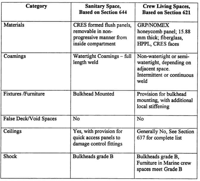
Table 2-1 summarizes the specifications for sanitary and crew living spaces. While the sanitary space specifications are based on section 644 and the crew living space
specifications are based on section 621, some specifications are derived from additional sources.
Category Sanitary Space, Crew Living Spaces, Based on Section 644 Based on Section 621 Materials CRES formed flush panels, GRP/NOMEX
removable in non- honeycomb panel; 15.88 progressive manner from mm thick; fiberglass, inside compartment HPPL, CRES faces Coamings Watertight Coamings - full Non-watertight or
semi-length weld watertight, depending on adjacent space.
Intermittent or continuous weld
Fixtures /Furniture Bulkhead Mounted Provision for bulkhead mounting, with additional local stiffening
False Deck/Void Spaces No No
Ceilings Yes, with provision for Generally No, See Section quick access panels to 637 for complete list damage control fittings
Shock Bulkheads grade B Bulkheads grade B, Furniture in Marine crew
spaces meet Grade B
3.0 Aircraft Carrier Construction
3.1 Nimitz Class Aircraft Carriers
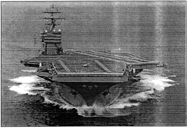
The Nimitz class aircraft carrier is the ultimate symbol of American naval power. These vessels are 1092 feet long, 252 feet wide on the flight deck, and displace over 97,000 tons full load. With over a 100 million parts and two nuclear reactors, they take over seven years to build. The two nuclear reactors generate steam for a 260,000 SHP power plant, driving the vessel at over 30 knots at full speed. The Nimitz class carrier can carry 85 aircraft, and is equipped with all the necessary hanger, maintenance, and support
equipment of a military airbase. In addition, she carries an extensive suite of electronics, communication, and radar systems.5 Figure 3-1 is a picture of a Nimitz Class Aircraft Carrier.
Figure 3-1 -A Nimitz Class Aircraft Carrier
5 Sharpe, Captain Richard, Editor, Jane's Fighting Ships 1997-1998, pp807, Butler and Tanner Limited, Great Britain, 1997.
The first vessel of the class, Nimitz, was delivered by Newport News Shipbuilding (NNS) in 1975. Since then, NNS has completed seven Nimitz class carriers, has two more under construction, and one more planned.
3.2 Newport News Shipbuilding, Inc.
Newport News Shipbuilding is the only facility in the world currently capable of building a nuclear powered aircraft carrier the size of the Nimitz. It is therefore important to understand the Newport News's history, facilities, and capabilities. Newport News Shipbuilding is America's largest privately-owned shipyard. Started in 1886, NNS has delivered more than 800 commercial and naval vessels, including 29 aircraft carriers. In addition to the two Nimitz class carriers currently under construction (CVN-75 and 76), NNS is building a series of double hull product tankers, and is in the process of
converting two commercial ships into strategic sealift ships. NNS also performs commercial and naval repair and overhaul work on a regular basis.
The shipyard itself is located on 550 acres along the James River, near Hampton Roads, VA. Its facilities include eight dry docks, two outfitting berths, and four outfitting piers; an 11-acre automated steel fabrication center, a 130,000 sq. ft module outfitting facility; a foundry complex, and 300,000 sq. ft of machine shops. Two of these dry docks are used in the construction and refueling of Nimitz Class aircraft carriers. New carriers are built in Dry Dock 12. This dry-dock is the largest in the western hemisphere, at over 2100 feet in length, and features a 900 ton capacity crane, also the most capable in the western hemisphere.6 Dry Dock 12 is currently divided in two, with Double Eagle tankers under construction on the river side, and the RonaldReagan (CVN-76) under construction on the inboard side. This dry dock has a 30' 6" draft limitation, so it is used exclusively for the construction of new carriers.' New carriers are launched before their draft exceeds
6 Newport News Shipbuilding, Facts and Figures. Public Relations Kit, December 1997.
7 Michael Powell, "CVX Modular Berthing." Briefing to Alan Brown and Gene Miller, NNS, Feb. 20, 1998.
this limit. Completed aircraft carriers do not meet the draft limitations of Dry Dock 12, and must use Dry Dock 11.
While Dry Dock 11 was originally used to build new aircraft carriers, it is the only dry dock at Newport News capable of accommodating a completed Nimitz Class aircraft carrier. Therefore, it is now used for overhauling and refueling existing nuclear-powered carriers. Dry Dock 11 only has a 310 ton crane, which is not capable of making some of the larger lifts currently used in the construction process for new carriers.
3.3 Habitability Spaces in Aircraft Carriers
Obviously, running a complex vessel of this size is a manpower intensive job. A Nimitz class aircraft carrier has a crew of over 6000, and a breakdown is given in Table 3-1.8 Of these, about half are associated with the air wing.
AIRCRAFT CARRIER CREW BREAKDOWN
Enlisted 5050
Marine 60
Marine 1t Sargent 1
Chief Petty Officers 347
Officers 567
TOTAL ACCOMMODATIONS 6025
Table 3-1 - Aircraft Carrier Crew Breakdown
In addition to bunk spaces for the crew, galley, washroom, office, and recreational spaces are all necessary, and take up a significant amount of space. However, finding this space in an aircraft carrier design is a difficult task.
8
Michael Powell, "CVX Modular Berthing." Briefing to Alan Brown and Gene Miller, NNS,Feb. 20, 1998.
3.4 Carrier Arrangement Design Hierarchy
The traditional design spiral begins with a concept design, which attempts to translate mission requirements into naval architectural and engineering characteristics. Based on the mission requirements, the first step is to estimate the vessel's proportions and
preliminary powering requirements. From the proportions, a lines plan and body plan are developed. Hydrostatics and floodable length curves are developed from the lines and body plan. Hull and Machinery arrangements are developed next, followed by structural design and powering. Once this is complete, a lightship weight estimate is created for intact and damaged stability studies. Finally, a cost estimate is developed. The cost estimate is used to determine whether to proceed with the program and to evaluate different concept designs. If the program proceeds, the spiral is repeated to develop a preliminary design.
The preliminary design locks in controlling factors such as length, beam, deadweight, and horsepower. The preliminary design serves as a foundation for the development of the contract design. The contract design loops around the spiral again, developing many of the features of the ship's design. This stage includes model testing, structural detail design, and the final general arrangement. The final general arrangement fixes the volumes and areas for each space, and defines their location in relation to other spaces and systems. The final stage is the detail design. The detail design is not so much an iteration that loops around the spiral, but rather the development of construction instructions which are passed from engineer to shipbuilder.
While an aircraft carrier follows the traditional design spiral, within the spiral the
development of general arrangements follows a definite hierarchy. The carrier's primary mission is to operate combat aircraft, and this is the first design priority, the mission requirement. As a result, aircraft launching, recovery, arming, and maintenance facilities are the most important systems in the ship's design. The electronic, radar, and
the design hierarchy. These systems will dictate the location and size of the flight deck, hanger deck, magazines, weapons elevators, and some control facilities.
The ship propulsion and protection systems are in the next level of the design hierarchy. This includes the nuclear reactors, propulsion turbines and shafting, and power
generation systems. Protection systems, both active (self defense missile systems and point defense guns) and passive (internal subdivision and structural protection systems) are also on this level. These requirements will dictate structural design and dominate the internal arrangements of the carrier's lower decks.
The preliminary design of an aircraft carrier considers all of the systems in the two highest design hierarchy levels. Because these are the most important systems, they need and require the "preferred" spaces in the carrier. "Preferred" spaces are those with the most regular geometry, best protection, or easiest access to the flight deck. Design trade-offs between systems in these levels are considered individually and carefully.
Toward the bottom of the design hierarchy are support and habitability systems. Within this level, briefing and mission-related office spaces have the highest priority. Galley and bunk spaces are next, and sanitary spaces are last. As a result of their low position in the design hierarchy, these systems are put in the remaining spaces after all the mission critical systems have been designed and placed. This often results in the assignment of habitability spaces to oddly shaped, difficult to access, and widely-separated locations.
Tanks and void spaces are unusual in the aircraft carrier arrangement design hierarchy. On one hand, they are at the bottom of the hierarchy because they are can fit in any unusual space left over after every other system is positioned. On the other hand, they must still meet certain requirements. Double bottom tanks and some wing tanks serve a secondary function as armor for critical spaces, and must be arranged and built
accordingly. In addition, the tanks must have enough capacity to carry the required amounts of aviation and diesel fuel to meet mission requirements. So while designers can usually allocate tanks and void spaces at the end of the arrangement design process,
they must still meet important requirements. Figure 3-2 illustrates the arrangement hierarchy.
3.5 Layout of Habitability Spaces
Figures 3-3 through 3-8 show the general arrangements of the Gallery Deck, 01, 02, Main deck, Second deck, and Third deck of the CVN 75, U.S.S. Theodore Roosevelt. The flight deck is located above the gallery deck, while the nuclear reactor and propulsion systems are located below the Third Deck. The majority of the habitability spaces are located on these six decks.
AIRCRAFT CARRIER ARRANGEMENT HIERARCHY
INPUTS: AIRWING SIZE & COMPOSITION,PROPULSION TYPE
SHIP PROPULSION & PROTECTION SYSTEMS
SUPPORT &
HABITABILITY
SYSTEMS
SOUTPUT: SHIP DESIGN
DRIVE DESIGN AND "FDIX" LOCATION & SIZE OF MANY SPACES PLACED IN REMAINING SPACES
3.5.1 Gallery Deck
The gallery deck contains significant berthing and galley space. Crew living spaces dominate the forward and aft-most quarters of the deck, and there are some galley spaces forward. The middle half of the deck is dominated by weapons elevators, radar display spaces, and the Combat Information Center spaces, with some staterooms interspersed. Catapult systems are located both forward and amidships to port. Storerooms occupy the outboard areas through the middle half of the deck. This is one of the "busiest" decks on the carrier because of the variety of systems.
3.5.2 02 Deck
The majority of the 02 level is open to the hanger bay. The anchor and line handling spaces are forward, and are immediately followed by crew spaces and staterooms. Storerooms are located outboard through the middle half of the deck, and more crew living spaces are located aft.
3.5.3 01 Deck
The majority of the 01 level is open to the hanger bay. The windlass room and several storerooms are located forward, and are immediately followed by crew living spaces and avionics shops. Storerooms are located outboard through the middle half of the deck, and crew living spaces and more aviation shops.
3.5.4 Main Deck
The hanger deck dominates the main deck level. Aviation shops are located forward and aft of the hanger bays. There are no living spaces on this level.
3.5.5 Second Deck
The second deck is dominated by living and galley spaces. Crew living spaces are located both forward and aft, with galley and mess spaces throughout the middle half of the deck. The mess spaces also serve as alternate weapon assembly spaces. The ship's hospital is also located on this deck.
Figure 3-3 - Gallery Deck Arrangement
C- i4a S.-!
= ' C- z 0(-ad~~.lY- ~ c.V or eIc,'c)(I~ ED ~ ~
Figure 3-5 - 01 Deck Arrangement _ _ ~ n
Pr4s- k'- u~l (
3.5.6 Third Deck
Crew living spaces are interspersed with weapons elevators, generator rooms, fan rooms, and access trunks throughout the forward half of the deck. There are several machine shops, film labs, and mail rooms amidships, with more state rooms, crew living areas, galley, and laundry spaces aft.
3.5.7 Other Considerations in Habitability Space Design
While habitability spaces are placed primarily where space allows, they are considered to have a secondary purpose as protection for the vital parts of the ship. As a result, they tend to be located outboard and above such mission critical spaces as the combat
information center, the hanger, and weapons elevators. Also, the original design for the lead vessel of the class is over 30 years old, and predates many environmental
regulations. As a result, many sanitary spaces were located outboard to facilitate overboard discharges. While changes in environmental regulations now prohibit
overboard discharge, the facilities have remained in the same locations. This necessitates long pipe runs to the furthest reaches of the ship.
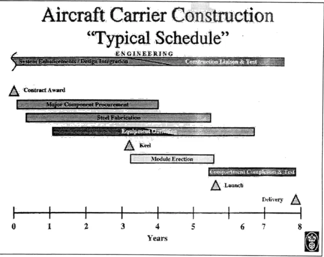
3.6 Aircraft Carrier Construction Schedule
The design of a new aircraft carrier class begins approximately 10 years before the first contract award. Figure 3-9 shows a Typical Aircraft Carrier Construction Schedule.9 Before an actual contract award, there is an advanced appropriation for long lead time material. This long lead time material includes the nuclear reactors. After contract award, it takes between seven and eight years until the finished carrier is delivered. Once the contract is awarded, major component procurement begins. This includes ordering the nuclear reactors and propulsion machinery. Steel fabrication begins three to six months after contract award, and equipment outfitting begins one year after contract award.
9 Michael Powell, "CVX Modular Berthing." Briefing to Alan Brown and Gene Miller, NNS, Feb. 20,
Aircraft Carrier
Construction
"Typical Schedule"
NIN lR IN G j " . -.-... ... .. ... .. .... .. . ... .. . 0 1 2 3 4 5 6 7 8 YearsFigure 3-9 - Typical Aircraft Carrier Construction Schedule
The keel is laid in the graving dock three years into the project. The midship hull modules are erected first, while subsequent modules are installed aft and above. This is done so time critical machinery components, located aft, can be installed as early as possible. Module erection continues in the graving dock for about two and half years until launch. After the carrier is launched it is moved to the outfitting pier, where outfitting begins in full and system tests are conducted. The compartment completion and testing phase lasts two and a half years, and the carrier is delivered eight years after contract award.
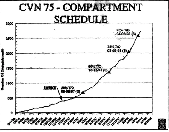
CVN
75- COMPARTMENT
-
SCH1EDULE
04.4%.T0
•2000
Figure 3-10 - Compartment Turnover Schedule
itsFigure finished, or "turned-over."3-compar0 - Comptment Turnover Schedules
3.7 Construction of Habitability Space
3.7.1 Reasons For On Ship Outfitting
There are several reasons Newport News performs the outfitting of habitability spaces on ship. Aside from the fact Newport News has always done -and is "set up" for - on ship outfitting, it continues this method for several reasons. First, the outfitting is not on the
critical path. Dry-dock limitations restrict launching weight, which limits the amount of preoutfitting possible. It is unlikely these constraints will change. Finally, on ship outfitting offers Newport News the greatest construction, schedule, and ordering lead time flexibility.
3.7.1.1 Critical Path
Outfitting the habitability spaces is not on the critical path. Before the ship is launched, construction of the stern section, including the propulsion shafting, and the installation of the nuclear propulsion equipment, drives the construction time. After launch, the main propulsion and nuclear systems testing forms the critical path. As a result, NNS
concentrates all of its initial efforts on installing the propulsion systems and shafting, and does not preoutfit habitability spaces.
3.7.1.2 Dry-dock Limitations
While new aircraft carriers are erected in Newport News' Dry Dock 12, the largest in the western hemisphere, the dock has a draft limitation of 30'- 6." New carriers are launched with just a few inches of clearance. Once a carrier is launched, it is not able to return to Dry Dock 12. As a result, there is little margin for the additional weight at launch associated with greater preoutfitting.' 0 Newport News has another dry dock that is capable of handling fully outfitted aircraft carriers, although it is presently used only for nuclear refuelings.
3.7.1.3 Flexibility
By outfitting the habitability spaces on ship, there is more flexibility in determining the exact layout of the spaces. This is useful as changing requirements for both the
habitability and surrounding spaces might require changes in habitability space size and
0o Interview with Michael Powell, at Newport News Shipbuilding. Conducted by Gene Miller and Dr. Alan Brown. Feb. 20 1998.
arrangement. In addition, piping, electrical, and HVAC systems are often routed from point to point. As the construction process evolves and more systems are installed, additional systems must be fitted around existing installations. This results in an apparently hap-hazard overhead arrangement. Outfitting the spaces on ship allows workers to work around these unanticipated pipe and electrical runs and HVAC ducts.
On ship outfitting also offers schedule and ordering lead time flexibility. Preoutfitting requires careful planning up front to sequence when particular areas are outfitted. If the schedule is off and blocks are not ready, it can delay the entire erection schedule.
Outfitting on ship does not carry the logistical and scheduling management burdens of preoutfitting. In addition, preoutfitting moves joiner material and furniture procurement up in the schedule. Since these items are not on the critical path, no matter when
installed, there is no incentive to order these items any sooner than necessary. Because module erection begins over four years before delivery, preoutfitting would require ordering items at least four years before the ship is delivered. During these four years, space and arrangement requirements could change. By waiting to outfit habitability spaces until after launch, ordering decisions can be postponed by two or more years.
3.7.2 Habitability Space Construction Method
The carrier is launched with some of the piping and overhead ventilation ducting already. installed in the habitability spaces. Installation of joiner bulkheads, coamings, and curtain plate is done after the carrier is moved to the outfitting pier. Coamings and curtain plates are first scribed to fit the installation location. The coamings and curtain plates are then cut to fit, leveled, and welded to the structure. Joiner bulkhead panels are then attached either directly to the coamings and curtain plates or with Z and H-clips, depending on the panel material and deflection requirements. The lagging work is also completed while the vessel is located at the outfitting berth. The lagging is installed after the structure is already completed in a space. Finally, the compartments are sealed off and painted. Painting causes major schedule disruptions.
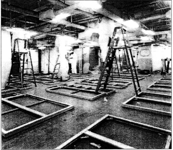
The furniture is installed after the lagging is in place. Like the joiner bulkhead coamings, each foundation is scribed to fit, cut, leveled, and welded to the deck. Each type of furniture (i.e. lockers, bunks, desks, chairs, tables) has a unique foundation. Figure 3-11 shows a crew berthing space with the locker and bunk foundations in place.
Figure 3-11 - Crew Berthing Space with Furniture Foundations Laid
Once the foundations are secure, the decks are leveled and the tile floor is laid down. Upon completion, the tile flooring is covered with protective sheets, and the furniture is brought into the compartment. The furniture is ordered from an independent vendor, and
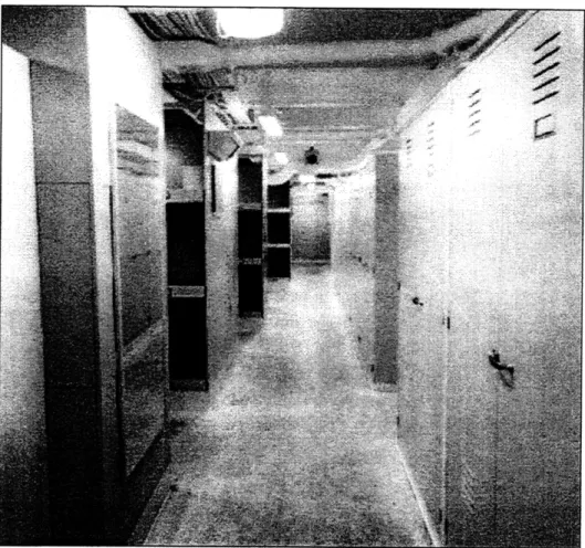
arrives unassembled in a "kit" form. Each bunk, locker, and table is then assembled, in position, by Newport News workers. A completed crew berthing space is shown in Figure 3-12.
Figure 3-12 - Completed Crew Berthing Space
Each crew berthing space may serve between 40 and 100 or more men. Crew living spaces are based on three bunk high units. The three bunk high units are arranged back to back, forming multiple six man semi-enclosures. Most bunks have under mattress
storage, with additional stowage space in nearby lockers. Community head and shower facilities are located in separate, nearby spaces.
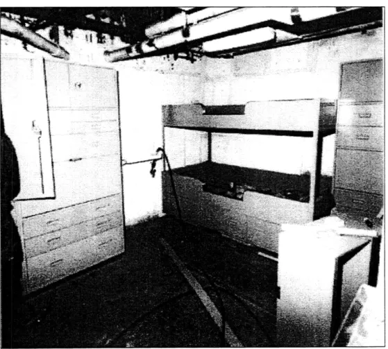
Officer Staterooms and common areas are completed in a similar method. Junior officer staterooms typically have two to four bunks, additional storage space in drawers and closets, and possibly a desk. Sanitary spaces are located in separate compartments. Junior officer staterooms have more individual space than the crew berthing spaces.