Publisher’s version / Version de l'éditeur:
Vous avez des questions? Nous pouvons vous aider. Pour communiquer directement avec un auteur, consultez la
première page de la revue dans laquelle son article a été publié afin de trouver ses coordonnées. Si vous n’arrivez
Questions? Contact the NRC Publications Archive team at
[email protected]. If you wish to email the authors directly, please see the first page of the publication for their contact information.
https://publications-cnrc.canada.ca/fra/droits
L’accès à ce site Web et l’utilisation de son contenu sont assujettis aux conditions présentées dans le site LISEZ CES CONDITIONS ATTENTIVEMENT AVANT D’UTILISER CE SITE WEB.
Student Report (National Research Council of Canada. Institute for Ocean
Technology); no. SR-2007-19, 2007
READ THESE TERMS AND CONDITIONS CAREFULLY BEFORE USING THIS WEBSITE. https://nrc-publications.canada.ca/eng/copyright
NRC Publications Archive Record / Notice des Archives des publications du CNRC :
https://nrc-publications.canada.ca/eng/view/object/?id=6dd09129-1e0b-479f-8561-37868fbe8104
https://publications-cnrc.canada.ca/fra/voir/objet/?id=6dd09129-1e0b-479f-8561-37868fbe8104
NRC Publications Archive
Archives des publications du CNRC
For the publisher’s version, please access the DOI link below./ Pour consulter la version de l’éditeur, utilisez le lien DOI ci-dessous.
https://doi.org/10.4224/8896147
Access and use of this website and the material on it are subject to the Terms and Conditions set forth at
Ballasting Slocum electric gliders
DOCUMENTATION PAGE
REPORT NUMBERSR-2007-19
NRC REPORT NUMBER---
DATEAugust 2007
REPORT SECURITY CLASSIFICATION DISTRIBUTION
TITLE
Ballasting Slocum Electric Gliders
AUTHOR(S)
Matthew Baird
CORPORATE AUTHOR(S)/PERFORMING AGENCY(S)
National Research Council, Institute for Ocean Technology (NRC-IOT)
PUBLICATION
---
SPONSORING AGENCY(S)
National Research Council, Institute for Ocean Technology (NRC-IOT)
IMD PROJECT NUMBER
42_2189_26
NRC FILE NUMBER
---
KEY WORDS
Buoyancy engine, ballasting, gliders, slocum, autonomous underwater vehicle, AUV,
PAGES FIGS. TABLES
SUMMARY
This report outlines the procedures and calculations required in performing the ballasting of Slocum Electric Gliders, a type of Autonomous Underwater Vehicle developed by Webb Research Corporation. It also outlines the MATLAB script that was developed for the purpose of simplifying the process of ballasting, through automation of the calculations and recording all pertinent data. The inputs are mass values and water conditions which are gathered from a combination of user inputs and an Excel™ file. The MATLAB script calculates the necessary mass changes and these values are displayed in the MATLAB Command window. All the data that was input, all the intermediate values, and all the final mass values are appended to a text file that is named based on the glider serial number. Thus the complete ballasting history of any particular glider is easily accessible. As well, all the final mass values are recorded to an Excel™ file, the same Excel™ file that is used as a source of inputs each time the script is executed.
ADDRESS
National Research Council
Institute for Ocean Technology
Arctic Avenue, P. O. Box 12093
St. John's, NL A1B 3T5
National Research Council Conseil national de recherches
Canada Canada
Institute for Ocean Institut des technologies
Technology océaniques
Ballasting Slocum Electric Gliders
42_2189_26
Matthew Baird
Summary
This report outlines the procedures and calculations required in performing the
ballasting of Slocum Electric Gliders, a type of Autonomous Underwater Vehicle
developed by Webb Research Corporation. It also outlines the MATLAB™ script
that was developed for the purpose of simplifying the process of ballasting,
through automation of the calculations and recording all pertinent data. The
inputs are mass values and water conditions which are gathered from a
combination of user inputs and an Excel™ file. The MATLAB™ script calculates
the necessary mass changes and these values are displayed in the MATLAB™
Command window. All the data that were input, all the intermediate values, and
all the final mass values are appended to a text file that is named based on the
glider serial number. Thus the complete ballasting history of any particular glider
is easily accessible. As well, all the final mass values are recorded to an Excel™
file, the same Excel™ file that is used as a source of inputs each time the script
is executed.
Table of Contents
Summary ... i
Table of Contents... ii
1. Introduction: What is a Slocum glider? ...1
2. The Purpose of Ballasting...2
3. The Purpose of MATLAB™ Script ...3
4. Explanation of Equations used in Ballasting Code:...3
4.1.
Neutral Buoyancy and Initial Pitch Angle Correction ...4
4.2.
Static Roll Correction ...6
4.3.
H-moment arm Correction ...17
4.4.
Explaining how the data is logged ...21
5. Conclusion and Recommendations ...26
Appendix A: MATLAB™ Script
Appendix B: A Command Window View of the Program
Appendix C: A Sample Text Log File
List of Figures
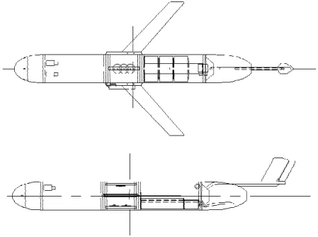
Figure 1: AutoCAD Drawings of Slocum Electric Glider by C. Knapp, August
2006...1
Figure 2: Glider Flight Path ...2
Figure 3: Cross-section of glider with non-zero initial roll angle ...7
Figure 4: Crossection of Glider Showing H-moment Calculations ...8
Figure 5: Cross-Section of glider Showing Unadjusted Battery and G positions.10
Figure 6: Cross-section of Glider after Battery Adjustment ...11
Figure 7: Cross-section of glider before roll mass adjustment ...13
Figure 8: Cross-Section of Glider after Roll Mass Adjustment ...14
Figure 9: Cross-Section of glider Showing the H-moment Adjustment ...18
1. Introduction: What is a Slocum glider?
The Electric Slocum Glider is an AUV (Autonomous Underwater Vehicle) that
was developed by the Webb Research Corporation. It is used for long-term
oceanographic studies. It can, with standard equipment, dive to 200 m and go on
mission lengths in the order of 4 weeks long, taking water column measurements
as it travels.
Figure 1: AutoCAD Drawings of Slocum Electric Glider by C. Knapp, August 2006
The standard sensor array is a conductivity, temperature, and depth sensor.
Modifications can be made to the glider to accommodate various other sensors
as well, such as dissolved oxygen sensors, or Photosynthetically Activated
Radiation (PAR) sensors. There is also a sonar housing unit which can be used
in place of the standard science section of the hull, which can house several
upward and downward looking sonar units, to observe the ocean floor and the
underside of icebergs. However, the cost to installing these extra sensors is a
reduced mission length, as the battery’s energy is consumed faster.
There are no external moving parts on the glider, which brings up the question of
how it is able to propel itself through the ocean. It does this with a buoyancy
engine, a mechanism that can manipulate the effective weight to cause
alternating upward and downward motion in water. Housed in the nose cone is a
piston that can ingest or expel water (maximum capacity of approx. 500 cm
3).
When the piston is at its zero position, mid-stroke, the glider is neutrally buoyant.
If it ingests water, it becomes negatively buoyant and sinks. Alternatively, if the
glider expels water, the glider becomes positively buoyant, and thus it will float.
The glider sinks, until it hits its target depth, then it expels water until it is
positively buoyant, and rises back towards the surface. When it reaches a target
depth, it ingests water again, so it will sink. A portion of the vertical motion that
results from the piston ingesting and expelling water is transformed to a
horizontal velocity due to hydrodynamic forces on the wings. Thus the glider has
a saw-tooth glide pattern through the water. Refer to Figure 2.
Figure 2: Glider Flight Path
Moving a mass in the forward section of the glider using a small linear actuator
controls the dive angle in the glider. A battery, referred to as the pitch control
battery, serves a dual purpose as both a power source and as this movable
mass. The battery moves back and forth to control the longitudinal position of the
centre of gravity, and thus controls the steepness of the angle of decent and the
angle of ascent. Also, the rudder on the tail is responsible for controlling the
glider’s heading.
2. The Purpose of Ballasting
Ballasting of a Slocum Electric Glider is important for two reasons, Due to the
nature of the buoyancy engine, neutral buoyancy is required for flight, it is also
important for energy consumption concerns. There are 4 parts to ballasting of a
Slocum glider; you need to adjust for neutral buoyancy, a zero pitch angle, a zero
roll angle, and an appropriate h-moment arm.
Of primary concern is ballasting for neutral buoyancy. If the glider is not ballasted
accurately to be neutrally buoyant, the volumetric capacity of the buoyancy
engine will not be able cause the glider to alternate between being negatively
and positively buoyant. If the glider cannot become both negatively and positively
buoyant by the action of the piston alone, then it simply cannot glide. The piston
Negatively
Buoyant
Positively
Buoyant
in the nose section, the mechanism behind the buoyancy engine, has a capacity
of ±250 cc, which is only 0.5% of the glider’s total volume. As well consider that
the density of the water in an area can vary slightly, reducing the range under
which the engine can still function.
Secondly, the pitch also needs to be adjusted, so that the glider when not in flight
has an initial pitch angle of zero degrees. The trim of the glider influences the
flight characteristics of the glider, having an initial pitch of zero means that the
glider has better control over its angle of decent and angle of ascent while
gliding, and ensures that the glider can achieve the programmed flight pattern,
and perform more efficiently.
Thirdly, for similar reasons as the adjustment of the pitch angle, the roll angle
also needs to be adjusted to zero. If the roll angle is not zero the rudder has to do
work constantly to adjust the heading of the glider. Energy consumption would
necessarily increase if this is the case, thus shortening the possible mission
lengths of the glider.
Finally, the h-moment arm needs to be properly adjusted. The h-moment arm is
the vertical distance between the centre of buoyancy (B) and the centre of gravity
(G). The length of the h-arm is related to the stability of the glider in the water, if
the arm is too long or too short the glider will be more likely to want to roll. With
an arm length of around 6 mm the glider is the most stable. The glider will
naturally adjust back to zero roll quickly after a disturbance, meaning that the
rudder isn’t required to do as much work, saving battery power.
3. The Purpose of the MATLAB™ Script
The processes in ballasting are calculation intensive and require dismantling and
reassembling the glider, making it time consuming. Any mistakes make the
process even more time consuming. There are two purposes behind developing
the MATLAB™ script. Automating the calculations to improve on the accuracy of
the calculations necessary for ballasting, which would reduce the time it takes to
ballast accurately. As well to create a permanent record all the data from the
calculations. The log of mass changes can be referred back to determine the
source of any mistakes made in ballasting. They can also be referred back to if
the glider is being flown under the same conditions, then it can be ballasted
without having to go through the calculations. Also the mass values are logged at
the end of each program to a rewritten Excel™ spreadsheet, which is then called
by the script each time it is run for that particular glider. This way the user doesn’t
necessarily have to input all the mass values into the program.
4. Explanation of Equations used in Ballasting Code:
What follows is the explanation of the processes that go into ballasting the glider.
Specifically the derivation of the formulas to determine the required mass
changes, and then the lines of code in the MATLAB™ script that correspond to
those calculations. The program does the calculations in the order of neutral
buoyancy and pitch, then roll, then h-moment.
4.1. Neutral Buoyancy and Initial Pitch Angle Correction
The first thing that needs to be done in the ballasting program is the glider must
be adjusted to neutral buoyancy and zero pitch. The glider is submerged in the
buoyancy tank, with spring scales attached at the fore and aft ends of the glider,
positioned directly above the positions of the plastic ballast bottles. These
masses and the dry mass, which is measured before submerging, will tell us
exactly how much mass needs to be added or removed to give us neutral
buoyancy. Then it gives you suggested masses for each bottle.
m
buoy tank=
m
dry@ mscale
m
scale=
m
bow total@ maft total
V
tank=
m
ρ
buoy tanktank ffffffffffffffffffffffffff
V
target=
V
tankB 1
+ α
B T
target@ T
tankb c
d e
m
target=
V
targetB
ρ
target∆
m
total=
m
target@ m
dry∆
m
bow=
m
scale+ ∆
m
total2
fffffffffffffffffffffffffffffffffffffffffffff@ m
bow∆
m
aft=
m
scale+ ∆
m
total2
fffffffffffffffffffffffffffffffffffffffffffff@ m
aftm
per bow tank=
m
port bow+
m
star bow+ ∆
m
bow2
fffffffffffffffffffffffffffffffffffffffffffffffffffffffffffffffffffffffffffffffffff
m
per aft tank=
m
upper aft+
m
lower aft+ ∆
m
aft2
fffffffffffffffffffffffffffffffffffffffffffffffffffffffffffffffffffffffffffffffff
m
buoy tank= the neutrally buoyant mass in the tank water.
m
dry= the dry mass of the glider.
m
bow/m
aft= the scale readings from the bow and aft spring scales.
V
tank= Volume of the glider at tank temperature.
V
target= Volume of the glider at target temperature.
α
= coefficient of thermal expansion for aluminium.
m
target= neutrally buoyant mass at target conditions.
Corresponding Code: (main function)
%Calculating the Saltwater Buoyancy (mass in kg) scale_tot = bow_scale + aft_scale;
tank_buoy = dry_mass - ( scale_tot )/1000;
disp (' ');
disp ( 'BALLASTING AND TRIMMING' );
Volume_tank = tank_buoy/tank_dens;
disp ( [ 'The volume of the glider at tank water temperature is: ' num2str( Volume temp)] ); disp ( ['The volume of the glider at target ocean temperature is: ' num2str( Volume_target ) 'm^3' ] );
sw_buoy = Volume_target * target_dens; %in kg _tank ) 'm^3' ] );
Volume_target = Volume_tank * ( 1 + expans_coeff * ( target_temp - tank_
disp (['The Neutrally Buoyant Mass in target Water at ' num2str(target_temp) ' degrees is: '
num2str( sw_buoy ) ' kg' ] );
ball_change = (sw_buoy - dry_mass) * 1000; %value in grams
disp (['The total ballast change must be: ' num2str( ball_change ) ' g' ] );
bow_change = (scale_tot + ball_change)/2 - bow_scale;
disp (['The total bow Ballast must be changed by: ' num2str( bow_change ) ' g' ] ); aft_change = (scale_tot + ball_change)/2 - aft_scale;
disp (['The total Aft Ballast must be changed by: ' num2str( aft_change ) ' g' ] ); %Assuming a simply splitting the difference to get the new tank masses bow_new = (( port_bow + star_bow ) + bow_change)/2;
aft_new = (( upper_aft + lower_aft ) + aft_change)/2;
if bow_new > 450 || bow_new < 0 || aft_new > 450 || aft_new < 0 disp (' ');
disp ('Warning: The required mass change is too great. Consider Removing a Disk Weight or rail weights to compensate.')
end disp (' ');
disp ( [ 'The new mass in each of the bow Ballast Bottles should be: ' num2str( bow_new ) ' g. (Total = ' num2str( 2 * bow_new ) ' g. )' ] );
disp ( [ 'The new mass in each of the Aft Ballast Bottles should be: ' num2str( aft_new ) ' g. (Total = ' num2str( 2 * aft_new ) ' g. )' ] );
disp ( ' ' );
upper_aft_new = input ( 'Enter the new mass of the top aft ballast bottle (g): ' ); lower_aft_new = input ( 'Enter the new mass of the lower aft ballast bottle (g): ' ); port_bow_new = input ( 'Enter the new mass of the port-bow ballast bottle (g): ' ); star_bow_new = input ( 'Enter the new mass of the starboard-bow ballast bottle (g): ' ); aux_mass = input ('Enter the mass of any additional ballast added (+) or removed (-) (g): ' );
%script that asks where the mass was removed from. Then recalculates the %masses needed in the ballast bottles
upper_aft_change = upper_aft_new - upper_aft; lower_aft_change = lower_aft_new - lower_aft; port_bow_change = port_bow_new - port_bow; star_bow_change = star_bow_new - star_bow;
mass_change = upper_aft_change + lower_aft_change + port_bow_change + star_bow_change + aux_mass;
new_mass = dry_mass + mass_change/1000; expected_scale = (new_mass - tank_buoy)*1000/2;
disp ( ' ' );
disp ( [ 'The new scale readings should be approximately ' int2str( expected_scale ) ' g'] ); disp ( [ 'The new mass of the Glider should be ' num2str( new_mass ) ' kg'] );
disp ( [ 'Should be approximately equal to ' num2str( sw_buoy ) ' kg to be neutrally buoyant' ] ); disp ( ' ');
Possible Problem: If changing the mass in the ballast bottles alone isn’t enough
to make the whole thing neutrally buoyant, you can specify how much mass is
removed, but not from where, if it is one of the other adjustable masses, like the
disk weights or the wing rail weights. The program would then have to calculate
the effect on pitch that removing or adding that moving this mass would have, if
any, and suggest new masses for the ballast bottles as a result. Presently, the
program will require you remove/add some mass, then start the program over.
4.2. Static Roll Correction
Now that the glider is ballasted for neutral buoyancy and a zero initial pitch angle,
we need to adjust for zero roll angle. To adjust the roll, we need to determine the
position of the glider’s centre of gravity, G
t(x
t, y
t). The first step to this end is to
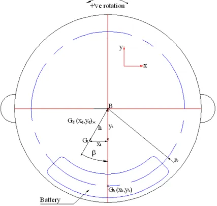
determine the initial roll angle. By placing the glider in the tank, with its wings
removed and supported by a hook in the nose section and a loop at the drop
weight in the tail section, it is free to rotate about its geometric centre, refer to
Figure 3. For simplicity’s sake we assume the centre of buoyancy, B,
corresponds with the geometric centre. The glider will rotate such that G
tcomes
to rest vertically below B. From the glider’s internal sensors we can determine the
value of this initial roll angle,
β
. This is our angular component of the position of
Figure 3: Cross-section of glider with non-zero initial roll angle
G
t(x
t, y
t) = x,y components of the battery’s centre of gravity
β
= initial roll angle
h = distance between centre of buoyancy and centre of gravity.
Next, we need to determine the h-moment arm, the distance between B and G
t.
With this we can determine the Cartesian coordinates of G
t. To do this we
suspend a known mass from the wing rail. This causes a rotation about B, by
some angle
θ
. When it comes to a new equilibrium, we can take the sensor
reading. By saying
Σ
M
B=0, we can calculate h for each mass. Use an average of
Figure 4: Crossection of Glider Showing H-moment Calculations
h
=
r B
m B cos
θ
` a
M B sin
bθ + β
c fffffffffffffffffffffffffffffffffffffffffffffffr = radius of outer hull = the moment arm of the applied masses.
M = Mass of the Glider
m = applied mass
θ
= sensor reading
Corresponding Code (Main function):
disp ( 'Roll Calculations');disp ( '=================');
roll_angle = input ('Enter the angle of roll according to the gliders sensor?'); mass_a = input ( 'Enter the 1st submerged mass applied to the Glider: ' ); sensor_a = input ( 'Enter the sensor reading under the applied mass: ' );
mass_b = input ( 'Enter the 2nd submerged mass applied to the Glider: ' ); sensor_b = input ( 'Enter the sensor reading under the applied mass: ' );
sensor_c = input ( 'Enter the sensor reading under the applied mass: ' );
h_a = ( mass_a * cos ( sensor_a ) ) * glider_r / ( new_mass * sin( sensor_a + roll_angle ) ); h_b = (mass_b * cos (sensor_b)) * glider_r / ( new_mass * sin( sensor_b + roll_angle ) ); h_c = (mass_c * cos (sensor_c) ) * glider_r / ( new_mass * sin( sensor_c + roll_angle ) ) h_avg = ((h_a + h_b + h_c)/3);
disp (['According to user input the h-moment arm is ' num2str(h_avg) ' (m)']);
Next the code plots the force applied to the glider, F versus the rotation,
α
, in
radians, to give us some measure of the righting moment, or the restoring
moment of the glider, and the stiffness of the glider.
Corresponding Code:
force_a = mass_a * g;alpha_a = sensor_a - roll_angle; force_b = mass_b * g;
alpha_b = sensor_b - roll_angle; force_c = mass_c * g;
alpha_c = sensor_c - roll_angle;
force = [ force_a force_b force_c ]; alpha = [ alpha_a alpha_b alpha_c ];
plot ( force, alpha )
The next step is to determine how we can best adjust the static roll angle to be
zero. First for calculation purposes we have to convert G
tfrom polar coordinates
to Cartesian coordinates. These coordinates are in the glider’s coordinate
system, centred on B, with the y-axis pointing to the top of the glider, and the
x-axis pointing towards the starboard side.
x
t=
@ h B cos
β
b cy
t=
@ h B sin
β
b cWe can now determine how to adjust this initial roll angle to zero, by
manipulating the battery position. We use centre of mass calculations to
determine the position of the battery that would change the x-component of the
glider’s centre of gravity to equal zero. We know or assume that:
1. The battery rotates around a fixed point, at a fixed radius
2. The battery’s mass.
3. The glider’s centre of gravity, (x
t ,y
t).
4. The battery’s initial centre of gravity, (x
b,y
b) = (0, -r
b).
We find the point G
g, (x
g, y
g), which is the centre of gravity of the glider if the
battery wasn’t present, thus it is independent of the angular position of the
battery, refer to Figure 5. For the initial roll angle to be zero the centre of gravity
of the glider has to be vertically below B. Therefore the target centre of gravity of
geometry and mass of the battery to determine where it has to be moved to give
a roll angle of zero. Moving the battery also has an affect on the length of the
h-moment arm, and the new h value is also calculated, refer to Figure 6.
Figure 5: Cross-Section of glider Showing Unadjusted Battery and G positions
x
g=
m
tBxt
m
g fffffffffffffffffffffy
g=
m
tB y
t+
m
bBr
bm
g ffffffffffffffffffffffffffffffffffffffffffffffffffffm
g=
m
t@ m
bFigure 6: Cross-section of Glider after Battery Adjustment
x
b=
@
m
gBxg
x
b fffffffffffffffffffffffϕ
b=
sin
x
br
b ffffff f gy
b=
@ r
b 2@ x
b 2 qwwwwwwwwwwwwwwwwwwwwwwwwwwwwwwwwwwwwwwwwwwwwwwwwwwwwwwwwwwwwwwwwwwwwwwwwwwwwwwwwwwwwwwwwwwwh.
=
@ yt.
=
@
y
gBmg
+
y
bBmb
m
t ffffffffffffffffffffffffffffffffffffffffffffffffffffffffG
g′
(x
g, y
g)= x,y components of the glider’s centre of gravity without the battery
G
b(x
b, y
b)= x,y components of the battery’s centre of gravity
G
b′
(x
b′
, y
b′
) = x,y components of the battery’s centre of gravity after repositioning
m
t= Total mass
m
b= Battery mass
r
b= radius of rotation of the battery, fixed.
m
g= Glider mass without battery.
h
′
= the h-moment arm after the battery adjustment
φ
b= the angular position of the battery
G
t′
(x
t′
, y
t′
) = x,y components of the battery’s centre of gravity after repositioning
Corresponding Code (Sub-function: posncalc.m):
function [theta, h_out] = posncalc ( h, beta, total_mass, battery_mass )
battery_r = 0.0635; %Constant total_x = - h * sin ( beta ); total_y = - h * cos ( beta );
glider_mass = total_mass - battery_mass;
glider_x = total_x * total_mass / glider_mass;
glider_y = (total_y * total_mass + battery_r * battery_mass) / glider_mass;
battery_x = - ( glider_x * glider_mass )/ battery_mass; battery_y = - sqrt( battery_r ^ 2 - battery_x ^ 2 );
theta = - sin ( battery_x / battery_r );
h_out = -(glider_y * glider_mass + battery_y * battery_mass ) / total_mass;
end
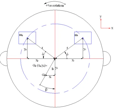
However it is possible that rotation of the battery is not sufficient to adjust the
initial roll angle to be zero. The battery has a limited range of rotation,
approximately 15˚ in either direction. If the required rotation ends up being
outside of this range, other internal masses have to be moved to compensate.
There are two other internal mass systems that can be adjusted to alter the static
roll conditions. There is a set of brass weights that are housed in the wing rails,
and there are the bow ballast bottles that are to the port and starboard sides.
These can both be examined using centre of mass calculations. You make the
maximum mass change that the system allows in the beneficial direction, and
Figure 7: Cross-section of glider before roll mass adjustment
x
g=
m
tBxt
@ m
sBx
s@ m
pB x
pm
g fffffffffffffffffffffffffffffffffffffffffffffffffffffffffffffffffffffffffffffffffffx
s=
r Bcos
δ
x
p=
@ r Bcos
δ
y
g=
m
tB yt
@ m
sB y
s@ m
pB y
pm
g ffffffffffffffffffffffffffffffffffffffffffffffffffffffffffffffffffffffffffffffffffffffy
s=
r Bsin
δ
y
p=
r B sin
δ
m
g=
m
t@ m
s@ m
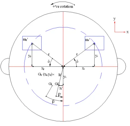
pFigure 8: Cross-Section of Glider after Roll Mass Adjustment
x
t.
=
x
gBm
g+
x
sB m
s.
+
x
pB m
p.
m
t fffffffffffffffffffffffffffffffffffffffffffffffffffffffffffffffffffffffffffffffffffffffffffh.
=
x
t.
2+
y
t 2 qwwwwwwwwwwwwwwwwwwwwwwwwwwwwwwwwwwwwwwwwwwwwwwwwwwwwwwwwwwwwwwwwwwwwwwwwwwwwwwwwwwwwwwwwwwwwwwwwwwwwwwwwwwwwwwwwwβ
.
=
tan
@ 1x
t.
y
t fffffffff f gx
g, y
g= x,y components of the glider centre of gravity without the mass system
m
g= Glider mass without mass system.
m
s= Starboard mass
m
p= Port mass
r
= distance to the centre of gravity of adjustable mass
β΄
= the resulting roll angle from the roll mass adjustment
There are some uncertainties in these calculations, we assume here that we
know that the centre of mass of the ballast bottles is at their geometric centre,
however this assumption is not perfectly true. The mass on the bottles is in the
form of lead shot, when the bottle is not 100% full the centre of mass will not be
at the bottles centre. Some later examination could result in a more accurate
approximation. For now we will use this simplifying assumption.
There are two limitations to the mass change that can be made in the ballast
bottles. A ballast bottle cannot hold more than 450 g of lead shot, and no new
mass can be added to the system without disturbing the neutral buoyancy
condition that is already established. Therefore the maximum mass in a ballast
bottle will either be the maximum capacity of that bottle or the sum of the mass in
that system, whichever is smaller. This also applies to the wing rail weights, but
in that system the maximum capacity is only 120 g.
Corresponding Code (Main function)
wing_max = port_wing + star_wing;if wing_max > 120, wing_max = 120; end
bow_max = port_bow_new + star_bow_new;
if bow_max > 450, bow_max = 450; end
In which direction does the mass have to be moved is the next question. We
know that if
β
is positive we want to create a clockwise rotation to counteract it.
Thus the maximum amount of mass will be moved towards the starboard side, in
the positive x direction. If
β
is negative we want to move the maximum amount of
mass towards the port side, in the negative x direction.
if
β>0
m
s.
=
m
maxand
m
p.
=
m
s+
m
p@ m
maxif
β
<0
m
p.
=
m
maxand
m
s.=
m
s+
m
p@ m
maxCorresponding Code: (cgchange.m)
function [beta_new, h_new, m_p_new, m_s_new] = cgchange( beta, h, m_t, m_p, m_s, m_max, r, delta) x_t = -h*cos(beta); y_t = h*sin(beta); m_g = m_t - (m_p + m_s)/1000; x_g = ( m_t * x_t + r * (( m_p - m_s )/1000) * cos( delta )) / m_g; if beta < 0 m_p_new = m_max/1000; m_s_new = ((m_p + m_s) - m_max)/1000; elseif beta > 0 m_s_new = m_max/1000; m_p_new = ((m_p + m_s) - m_max)/1000; end
x_t_new = (x_g * m_g + x_s * m_s_new + x_p * m_p_new)/m_t; h_new = sqrt( x_t_new^2 + y_t^2);
beta_new = atan ( x_t_new/y_t);
end
The adjusted initial roll angle and h-moment arm values are then plugged into the
battery position function to determine the new battery position that will result in a
zero initial roll angle. This happens three times; first with wing rail weights
adjusted, then with the ballast bottles adjusted, then both the wing rails and the
ballast bottles are adjusted. The first adjustment that produces an initial roll angle
of zero is the mass adjustment that the script suggests using.
Corresponding code (Main Function):
[theta, h_out] = posncalc ( h_avg, roll_angle, new_mass, battery_mass); %battery only [ beta2, h2, port_wing_new, star_wing_new ] = cgchange ( roll_angle, h_avg, new_mass, port_wing, star_wing, wing_max, wing_r, wing_delta);
[theta2, h_out2] = posncalc ( h2, beta2, new_mass, battery_mass); %battery and wing rail weights
[ beta3, h3, port_bow_new1, star_bow_new1 ] = cgchange ( roll_angle, h_avg, new_mass, port_bow_new, star_bow_new, bow_max, bow_r, bow_delta);
[theta3, h_out3] = posncalc (h3, beta3, new_mass, battery_mass); %battery and ballast bottles [ beta4, h4, port_bow_new1, star_bow_new1 ] = cgchange ( beta2, h2, new_mass,
port_bow_new, star_bow_new, bow_max, bow_r, bow_delta );
[theta4, h_out4] = posncalc (h4, beta4, new_mass, battery_mass); %battery, ballast bottles, and wing rails s
%If the required battery motion is too large, then adjust the wing rail weights
if abs(theta) < phi_max port_wing_f = port_wing; star_wing_f = star_wing; port_bow_f = port_bow_new; star_bow_f = star_bow_new; h_roll = h_out;
disp ( ' Movement of the battery alone is enough to adjust the static roll.' )
disp ( [ 'Move the battery to: ' num2str( theta ) ' radians. ' num2str( theta * 180 / pi ) ' degrees.' ] );
elseif abs(theta) > phi_max
disp ('The Battery cannot be rotated enough to compensate for the static roll.')
%If the required battery motion is too large, then adjust the wing rail weights if abs(theta2) < phi_max port_wing_f = port_wing_new; star_wing_f = star_wing_new; port_bow_f = port_bow_new; star_bow_f = star_bow_new; h_roll = h_out2;
disp ( 'Using the wing rail weights to compensate: ' );
disp ([ 'The new mass in the port side wing rail is (g): ' num2str(port_wing_new) ]); disp ([ 'The new mass in the star side wing rail is (g): ' num2str(star_wing_new) ]); disp ( [ 'Move the battery to: ' num2str( theta2 ) ' radians. ' num2str( theta2 * 180 / pi ) ' degrees.' ] );
disp ('The wing rail weights and battery combined are not enough to compensate for the static roll.') if abs(theta3) < phi_max port_wing_f = port_wing; star_wing_f = star_wing; port_bow_f = port_bow_new1; star_bow_f = star_bow_new1; h_roll = h_out3;
disp ( 'Using the bow ballast bottles to compensate: ' );
disp ([ 'The new mass in the port side ballast bottle is: ' num2str(port_bow_new1) ]); disp ([ 'The new mass in the starboard side ballast bottle is: ' num2str(star_bow_new1) ]); disp ( [ 'Move the battery to: ' num2str( theta3 ) ' radians. ' num2str( theta3 * 180 / pi ) ' degrees.' ] );
elseif abs(theta3) > phi_max
disp ('The Ballast bottles and battery combined are not enough to compensate for the static roll.') if abs(theta4) < phi_max port_wing_f = port_wing_new; star_wing_f = star_wing_new; port_bow_f = port_bow_new2; star_bow_f = star_bow_new2; h_roll = h_out4;
disp ([ 'The new mass in the port side ballast bottle is: ' num2str(port_bow_new1) ]); disp ([ 'The new mass in the starboard side ballast bottle is: ' num2str(star_bow_new1) ]);
disp ([ 'The new mass in the port side wing rail is: ' num2str(port_wing_new) ]); disp ([ 'The new mass in the star side wing rail is: ' num2str(star_wing_new) ]);
disp ( [ 'Move the battery to: ' num2str( theta4 ) ' radians. ' num2str( theta4 * 180 / pi ) ' degrees.' ] );
elseif abs(theta4) > phi_max
disp ('There is no way to adjust the mass to account for the roll, using the battery, wing rail weights , and the bow ballast bottles.')
end end end
end
4.3. H-moment arm Correction
As stated by the documentation that is provided by the manufacturer the optimal
length of the h-moment arm, the distance between B and G of the glider, is 6
mm. This length will make the glider the most stable in roll, a condition called
self-righting. There are two sets of masses that can be moved and adjusted to
manipulate the h-moment arm, the lead disk weights and the aft ballast bottles.
The bottles can have any mass between zero and the system maximum. Disk
weights can only be adjusted by changing the position from the top to the bottom
or vice versa, depending on the positioning of the disks. A mass can only occupy
the position it is in or the position directly above or below it. Otherwise the
movement could negatively affect the zero pitch condition established earlier.
First we must look at whether or not the h-moment can be adjusted by moving
the mass in the ballast bottles only. Using the same principle as was used to
determine the battery position, we can determine the centre of gravity of the
glider if the ballast bottles were not present. Then by setting our h to the optimum
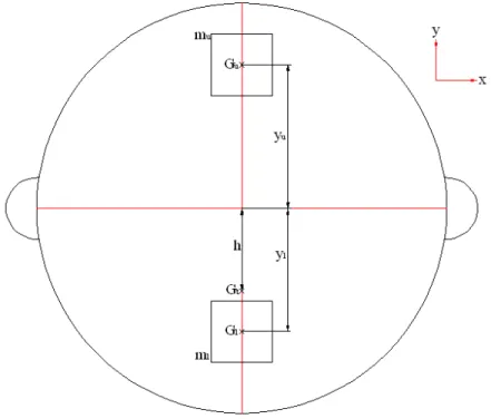
value, determine the new ballast bottle masses. Refer to Figure 9.
Figure 9: Cross-Section of glider Showing the H-moment Adjustment
y
g=
m
tB y
t+
m
uB r
u+
m
lB r
lm
gfffffffffffffffffffffffffffffffffffffffffffffffffffffffffffffffffffffffffffffffff
m
g=
m
t@ m
u@ m
lNow you need to know what mass changes that will give you the desired h
΄
.
y
t=
m
gB y
g@ m
u. B r
u@ m
l. B r
lm
t fffffffffffffffffffffffffffffffffffffffffffffffffffffffffffffffffffffffffffffffffffffffffffm
u.
=
m
u+ ∆
m
l.
=
m
l@
∆
Rearrange this formula, solving for
∆
, which will give you the necessary masses
∆ =
@
m
tB hopt
+
m
gB yg
+
m
uB ru
+
m
lB rl
r
u@ rl
ffffffffffffffffffffffffffffffffffffffffffffffffffffffffffffffffffffffffffffffffffffffffffffffffffffffffffffffffffffff
If one of the masses is outside of the realm of possibility; less than zero or
greater than the system maximum, then the function sets the appropriate mass to
the maximum, and the other to the minimum, depending on whether or not the
original h was less than or greater than zero. Then;
h
out=
@
m
gB y
g+
m
u.
b cB r
u+
m
l. b cB rl
m
t ffffffffffffffffffffffffffffffffffffffffffffffffffffffffffffffffffffffffffffffffffffffffffffffffffffffffwhere m
u΄΄
and m
l΄΄
are the nearest closet possible masses to the ideal masses.
Otherwise, if the mass change is within the realm of the possible, h
outis h
opt, and
no mass need move within the disk weight system.
Corresponding Code ( last.m)
function [h_out, upper_out, lower_out ] = last(m_t, upper, lower, h) %Calculating the mass change required in the ballast bottles h_opt = 0.006;
r_upper = 0.072; r_lower = -0.058;
m_max = upper + lower;
if m_max > 450, m_max = 450; end
m_g = m_t - ( lower + upper )/1000;
y_g = ( (lower/1000) * r_lower + (upper/1000) * r_upper - m_t * h) / m_g
del = - ( m_t * h_opt + m_g * y_g + (upper/1000) * r_upper + (lower/1000) * r_lower ) / ( r_upper - r_lower);
upper_out = upper + del*1000; lower_out = lower + del*1000; disp (upper_out);
disp (lower_out);
if upper_out > 450 || upper_out < 0 || lower_out > 450 || lower_out < 0 disp ( 'The optimum h-arm is not possible.');
if h > h_opt
upper_out = m_max;
lower_out = ( upper + lower - m_max );
elseif h < h_opt lower_out = m_max;
upper_out = ( upper + lower - m_max ); end
h_out = - ( m_g * y_g + (upper_out/1000) * r_upper + (lower_out/1000) * r_lower) / m_t;
else
h_out = h_opt;
If it turns out that h
outis not the ideal, we can begin shifting masses around in the
disk weight system. We move all of the masses around using the software to see
what effect each arrangement has on the h-moment. Then determine if the target
h is possible with some arrangement of the disks and ballast bottles.
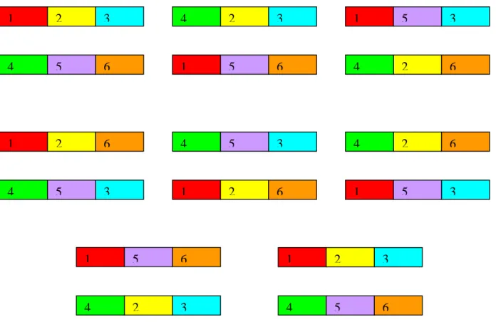
Note that for the disk weights, they are limited to being moved vertically, because
any horizontal motion can cause a disruption in the trimming. The mass in
forward top position, position 1 in the following diagrams, can only be switched
with the mass that is in the forward bottom position, position 4 in the following
diagram, and so on. This limits the number of possible mass arrangements to 7.
Refer to Figure 10.
Figure 10: Diagram Showing the Possible Disk Weight Positions
Corresponding Code (main Function)
m_top = (At+Bt+Ct);m_bottom = (Ab+Bb+Cb); h_opt =0.006;
%available mass changes. del_m1 = At - Ab; del_m2 = Bt - Bb;
1
3
2
4
6
5
1
3
2
4
6
5
1
2
3
4
5
6
1
3
2
4
6
5
1
3
2
4
6
5
1
3
2
4
6
5
1
3
2
4
6
5
1
2
3
4
5
6
del_m3 = Ct - Cb;
del_m4 = del_m1 + del_m2; del_m5 = del_m1 + del_m3; del_m6 = del_m2 + del_m3;
del_m7 = del_m1 + del_m2 +del_m3;
Now to determine the new h moment that moving the disks weights can produce.
Using the same procedure as before, determine the y component of the gliders
centre of gravity, if the disk weights were removed.
y
g=
@
m
tB h
+
r
dB m
u@ ml
` am
g ffffffffffffffffffffffffffffffffffffffffffffffffffffffffffffffffffffffffm
g=
m
t@ m
u+
m
l b cTaking each possible mass change in turn, determine what the new h would be
using:
h.
=
m
l. @ mu. b cBr @ mg
B yg
m
t ffffffffffffffffffffffffffffffffffffffffffffffffffffffffffffffffffffffffffffffffffm
l.
=
m
l+ ∆
dm
u.
=
m
u@
∆
dCorresponding Code: (Sub-function newhcalc.m)
function h_new = newhcalc ( m_top , m_bottom, mass_change, m_t, h ) r = 0.07;
m_g = m_t - ( m_top + m_bottom ); %mass of glider without disk weights
y_g = - ( m_t * h + r * ( m_top - m_bottom ) ) / m_g; %centre of gravity of glider without disk weights
m_top_new = m_top - mass_change;
m_bottom_new = m_bottom + mass_change;
h_new = ((m_bottom_new - m_top_new) * r - m_g * y_g ) / m_t;
end
4.4. Explaining how the data are logged
The mass log is an Excel™ file that records the values of the adjustable masses
in the glider after the ballasting procedure is complete. Each time the script is
executed it looks for the file corresponding to the glider name that the user
inputs. If no such file exists, it is created, and the user is asked to input the mass
values. If it does already exist, the program reads the mass values from the
Excel™ file, they are displayed on the screen and it asks the user if they are
correct. If the user says no, then the user is asked to input the correct mass
values.
logname = [ 'glider ' glider ' mass log']; var = exist ([ logname '.xls'], 'file' );
if var == 2
data = xlsread (logname , 'A1:A14');%Is there a way to limit how much of the file is read? upper_aft = data (1,1); lower_aft = data (2,1); port_bow = data (3,1); star_bow = data (4,1); port_wing = data (5,1); star_wing = data (6,1); battery_mass = data (7,1); At = data (8,1); Bt = data (9,1); Ct = data (10,1); Ab = data (11,1); Bb = data (12,1); Cb = data (13,1);
disp ( [ 'Mass in the upper aft bottle (g): ' num2str(upper_aft) ] ); disp ( [ 'Mass in the lower aft bottle (g): ' num2str(lower_aft) ] ); disp ( [ 'Mass in the port side bow bottle (g): ' num2str(port_bow) ] ); disp ( [ 'Mass in the starboard side bow bottle (g): ' num2str(star_bow) ] ); disp ( [ 'Mass in the portside wing rail: (g): ' num2str(port_wing) ] ); disp ( [ 'Mass in the starboardside wing rail (g): ' num2str(star_wing) ] ); disp ( [ 'The Roll control battery mass (kg): ' num2str(battery_mass) ] ); disp ( [ 'Mass in Position 1 (kg): ' num2str(At)]);
disp ( [ 'Mass in Position 2 (kg): ' num2str(Bt)]); disp ( [ 'Mass in Position 3 (kg): ' num2str(Ct)]); disp ( [ 'Mass in Position 4 (kg): ' num2str(Ab)]); disp ( [ 'Mass in Position 5 (kg): ' num2str(Bb)]); disp ( [ 'Mass in Position 6 (kg): ' num2str(Cb)]); j = input ('Are these values correct (y/n)? ', 's');
elseif var ==0 j = 'n';
end if j == 'n'
upper_aft = input ( 'Enter the mass of the top aft ballast bottle (g): ' ); if upper_aft > 450 || upper_aft < 0
disp ( 'Error: Mass is impossible' );
upper_aft = input ('Re-enter the mass of the top aft ballast bottle (g): ' ); end
lower_aft = input ('Enter the mass of the bottom aft ballast bottle (g): ' ); if lower_aft > 450 || lower_aft < 0
disp ( 'Error: Mass is impossible' );
lower_aft = input ('Re-enter the mass of the bottom aft ballast bottle (g): ' ); end
port_bow = input ('Enter the mass of the port-bow ballast bottle (g): ' ); if port_bow > 450 || port_bow < 0
disp ( 'Error: Mass is impossible' );
port_bow = input ('Re-enter the mass of the port-bow ballast bottle (g): ' ); end
if star_bow > 450 || star_bow < 0 disp ( 'Error: Mass is impossible' );
star_bow = input ('Re-enter the mass of the starboard-bow ballast bottle (g): ' ); end
port_wing = input ('Enter the mass in port-side wing rail (g): ' ); star_wing = input ('Enter the mass in starboard-side wing rail (g): ' ); battery_mass = input ('Enter the mass of the Roll control Battery? (kg)'); At = input ('Mass in position 1 (g): ')/1000;
Bt = input ('Mass in position 2 (g): ')/1000; Ct = input ('Mass in position 3 (g): ')/1000; Ab = input ('Mass in position 4 (g): ')/1000; Bb = input ('Mass in position 5 (g): ')/1000; Cb = input ('Mass in position 6 (g): ')/1000;
end
The program uses these values in its calculations and changes are made to the
actual masses within the glider. At the end of the program the changed mass
values are recorded to the mass log file, over-writing the values that are present.
Thus the next time the program is run for that particular glider, it can read the
most recent mass changes.
Corresponding Code (Main Function):
data = [upper_aft_f; lower_aft_f;port_wing_f; star_wing_f; port_bow_f; star_bow_f; battery_mass; At_f; Bt_f; Ct_f; Ab_f; Bb_f; Cb_f];
xlswrite (logname , data); %write to excel file
Also all the values that are input and calculated by the program are written to a
text log file. There is a unique file for each glider, and the new data from each
ballasting is appended to the end of the file.
Corresponding Code (Main function):
%code to append the data to one continuous file orig_dir = cd;
dirname = [ 'glider ' glider ' log.txt'];
path_name = 'M:\Ballasting Program\LOG\'; check_dir = isdir (path_name);
if check_dir == 0 mkdir (path_name)
end
cd (path_name); %changes directory
fid = fopen ( dirname, 'at' ); %use this line for continuous log fileinfo = dir( dirname );
fprintf ( fid, [ 'Ballasting for glider ' glider '.\nDate and Time of ballasting: ' fileinfo.date ] ); fprintf ( fid, [ '\n\nInitial mass of the glider: ' num2str( dry_mass ) ' kg.' ] );
fprintf ( fid, [ '\nTop aft bottle mass: ' num2str( upper_aft ) ' g.' ] ); fprintf ( fid, [ '\nBottom aft bottle mass: ' num2str( lower_aft ) ' g.' ] );
fprintf ( fid, [ '\nPort-bow bottle mass: ' num2str( port_bow ) ' g.' ] ); fprintf ( fid, [ '\nStar-bow bottle mass: ' num2str( star_bow ) ' g.' ] ); fprintf ( fid, [ '\nPort side wing rail mass: ' num2str( port_wing ) ' g.' ] ); fprintf ( fid, [ '\nStar-side wing rail mass: ' num2str( star_wing ) ' g.' ] ); fprintf ( fid, [ '\nRoll Battery mass: ' num2str( battery_mass ) ' kg.' ] ); fprintf ( fid, [ '\nMass of disk in position A top: ' num2str(At) ' g.'] ); fprintf ( fid, [ '\nMass of disk in position B top: ' num2str(Bt) ' g.'] ); fprintf ( fid, [ '\nMass of disk in position C top: ' num2str(Ct) ' g.'] ); fprintf ( fid, [ '\nMass of disk in position A bottom: ' num2str(Ab) ' g.'] ); fprintf ( fid, [ '\nMass of disk in position B bottom: ' num2str(Bb) ' g.'] ); fprintf ( fid, [ '\nMass of disk in position C bottom: ' num2str(Cb) ' g.'] ); fprintf ( fid, [ '\n\nTank water density: ' num2str( tank_dens ) ' kg/m^3.' ] ); fprintf ( fid, [ '\nTank water temperature: ' num2str( tank_temp ) ' C.' ] ); fprintf ( fid, [ '\nTarget water density: ' num2str( target_dens ) ' kg/m^3.' ] ); fprintf ( fid, [ '\nTarget water temperature: ' num2str( target_temp ) ' C.' ] ); fprintf ( fid, [ '\n\nBow spring scale reading: ' num2str( bow_scale ) ' g.' ] ); fprintf ( fid, [ '\nAft spring scale reading: ' num2str( aft_scale ) ' g.' ] ); fprintf ( fid, [ '\nTotal spring scale reading: ' num2str( scale_tot) ' g.' ] );
fprintf ( fid, [ '\n\nNeutrally buoyant mass in tank conditions: ' num2str( tank_buoy ) ' kg.' ] ); fprintf ( fid, [ '\nVolume in tank conditions: ' num2str( Volume_tank ) ' m^3.' ] );
fprintf ( fid, '\nUsed a coefficient of thermal expansion for Aluminum of 0.00007 /C'); fprintf ( fid, [ '\nVolume in target conditions: ' num2str( Volume_target ) ' m^3.'] );
fprintf ( fid, [ '\nNeutrally buoyant mass in target conditions: ' num2str( sw_buoy ) 'kg.' ] ); fprintf ( fid, [ '\n\nThe total required change in mass: ' num2str( ball_change ) ' g.' ] );
fprintf ( fid, [ '\nThe required change in mass in each aft ballast bottle: ' num2str( aft_change ) ' g.'
] );
fprintf ( fid, [ '\nThe required change in mass in each bow ballast bottle is: ' num2str( bow_change ) ' g.' ] );
fprintf ( fid, [ '\nThe new mass required in each bow ballast bottle is: ' num2str( bow_new ) ' g. Or, a total of ' num2str( 2*bow_new ) ' g in the bow tanks.' ] );
fprintf ( fid, [ '\nThe new mass required in each aft ballast bottle is: ' num2str( aft_new ) ' g. Or, a total of ' num2str( 2*aft_new ) ' g in the aft tanks.' ] );
fprintf ( fid, [ '\n\nThe new mass of the upper aft ballast bottle: ' num2str( upper_aft_new ) ' g.' ] ); fprintf ( fid, [ '\nThe new mass of the lower aft ballast bottle: ' num2str( lower_aft_new ) ' g.' ] ); fprintf ( fid, [ '\nThe new mass of the port-bow ballast bottle: ' num2str( port_bow_new ) ' g.' ] ); fprintf ( fid, [ '\nThe new mass of the star-bow ballast bottle: ' num2str( star_bow_new ) ' g.' ] ); fprintf ( fid, [ '\nThe new mass of the port-bow ballast bottle: ' num2str( port_bow_new ) ' g.' ] ); fprintf ( fid, [ '\nAdditional mass removed: ' num2str( aux_mass ) ' g.' ] );
fprintf ( fid, [ '\nThe total mass change was: ' num2str( mass_change ) ' g.'] ); fprintf ( fid, [ '\n\nThe new mass of the glider is: ' num2str( new_mass ) 'kg.' ] );
fprintf ( fid, [ '\n\nThe scale readings for Neutral Buoyancy and even trim should read: ' int2str( expected_scale ) ' g.' ] );
fprintf ( fid, [ '\n\nInitial Roll angle: ' num2str(roll_angle) ]); fprintf ( fid, [ '\nFirst applied Mass: ' num2str(mass_a) ]); fprintf ( fid, [ '\nFirst Sensor Reading: ' num2str(sensor_a)]); fprintf ( fid, [ '\nFirst Calculated h-moment arm: ' num2str(h_a)]); fprintf ( fid, [ '\nSecond Applied Mass: ' num2str(mass_b) ]); fprintf ( fid, [ '\nSecond Sensor Reading: ' num2str(sensor_b)]); fprintf ( fid, [ '\nSecond Calculated h-moment arm: ' num2str(h_b)]); fprintf ( fid, [ '\nThird Applied Mass: ' num2str(mass_c) ]);
fprintf ( fid, [ '\nThird Sensor Reading: ' num2str(sensor_c)]); fprintf ( fid, [ '\nThird Calculated h-moment arm: ' num2str(h_c)]); fprintf ( fid, [ '\nAverage h-moment arm: ' num2str(h_avg)]);
fprintf ( fid, [ '\n\nBattery position required, battery only: ' num2str(theta)]);
fprintf ( fid, [ '\n\nBattery position required, battery and wing rail weights: ' num2str(theta2)]); fprintf ( fid, [ '\n\nBattery position required, battery and Bow ballast bottles: ' num2str(theta3)]);
fprintf ( fid, [ '\n\nBattery position required, battery, wing rail weights, and Bow Ballast bottles: '
num2str(theta4)]);
fprintf ( fid, [ '\n\nAdjusted Port Wing Rail Mass: ' num2str(port_wing_new)]); fprintf ( fid, [ '\n\nAdjusted Starboard Wing Rail Mass: ' num2str(star_wing_new)]); fprintf ( fid, [ '\n\nAdjusted Port Ballast bottle mass: ' num2str(port_bow_new1)]); fprintf ( fid, [ '\n\nAdjusted starboard Ballast bottle mass: ' num2str(star_bow_new1)]); fprintf ( fid, [ '\n Final Mass of disk in position A top: ' num2str(At_f) ' g.'] );
fprintf ( fid, [ '\n Final Mass of disk in position B top: ' num2str(Bt_f) ' g.'] ); fprintf ( fid, [ '\n Final Mass of disk in position C top: ' num2str(Ct_f) ' g.'] ); fprintf ( fid, [ '\n Final Mass of disk in position A bottom: ' num2str(Ab_f) ' g.'] ); fprintf ( fid, [ '\n Final Mass of disk in position B bottom: ' num2str(Bb_f) ' g.'] ); fprintf ( fid, [ '\n Final Mass of disk in position C bottom: ' num2str(Cb_f) ' g.'] ); %fprintf ( fid, [ '\n : ' num2str()]);
fprintf ( fid,
'\n\n=====================================================================\n \n');
%closing file so it can be read fclose (fid);
5. Conclusion and Recommendations
The MATLAB™ Script that was created for aiding in the ballasting of the Slocum
Electric Gliders should effectively reduce the time it takes to properly perform
ballasting through automation of the calculations that need to be performed and
reducing the amount of “guess work” that was utilized in ballasting in the past.
Reducing mistakes is important in this application because to correct an error in
ballasting is time consuming, as it requires dismantling the glider, to various
degrees, in order to change a mass. However, at this time the reliability of the
calculations used here have yet to be properly tested, due to equipment
problems in the lab. I would suggest that at the soonest possible occasion the
script should be tested for reliability, and any errors found, either in code syntax
or in formulae be corrected. Then it can be utilized along with the existing
ballasting procedures.
As well, a GUI, Graphical User Interface, program should also be developed for
this procedure. A GUI is more flexible for user inputs, and this could possibly
allow the person using the program to experiment with the mass values inside
the system to a greater extent and to find any alternate solutions to the mass
change issues. As well, this GUI could then be developed into a stand-alone
program and marketed to other organizations that use the Slocum Electric
Gliders for oceanographic studies.
Appendix A:
MATLAB™ Script
17/08/07 2:38 PM C:\Documents and Settings\BairdM\Desktop\CD\...\ballastinga1.m 1 of 14
function saltwater = ballastinga1
%========================================================================== %ballastinga1.m Calculates the necessary mass changes to be made in the %Slocum Gliders to make it:
%A. Neutrally Buoyant %B. Even in Pitch %C. Even in Roll
%D. Adjust the h-arm to 6mm or as close as is possible.
%It then logs the mass changes to a rewritable .xls file, and the %calculated values are logged in a .txt file, whic will hold all the %ballasting data for each particular glider.
%
%Required inputs, tank density, tank temperature, target density, target %temperature. Glider dry mass, Ballast tank masses, Disk masses, readings %taken from roll sensor.
%
%Created by: Matthew Baird last updated August 17, 2007
%==========================================================================
%constants
tank_dens = 1000; % density of Freshwater = 1000 kg/m^3
expans_coeff = 0.00007; % Coefficient of Thermal Expansion for Aluminium g = 9.81; %gravity
phi_max = 0.2880; %max angle that the battery can be rotated ( + or - ) NTC glider_r = 0.1065; %radius of glider
wing_r = 0.11; %distance from the centre of the wing weights NTC wing_delta = 0; %offset angle for the wing weights
bow_r = 0.0749; %distance from the centre to the centre of bow ballast bottles NTC bow_delta = -.975; %offset angle for the ballast bottles. NTC
%Requesting Inputs from User disp( 'INPUTS' );
glider = input ( 'Ballasting for glider: ', 's' );
%Reading from Mass log, if it exists, and asking the user if the mass %values are correct.
logname = [ 'M:\Ballasting Program\LOG\glider ' glider ' mass log']; %logname = [ 'glider ' glider ' mass log'];
var = exist ([ logname '.xls'], 'file' ); if var == 2
data = xlsread (logname , 'A1:A14'); upper_aft = data (1,1); lower_aft = data (2,1); port_bow = data (3,1); star_bow = data (4,1); port_wing = data (5,1); star_wing = data (6,1); battery_mass = data (7,1);
17/08/07 2:38 PM C:\Documents and Settings\BairdM\Desktop\CD\...\ballastinga1.m 2 of 14 At = data (8,1); Bt = data (9,1); Ct = data (10,1); Ab = data (11,1); Bb = data (12,1); Cb = data (13,1);
disp ( [ 'Mass in the upper aft bottle (g): ' num2str(upper_aft) ] ); disp ( [ 'Mass in the lower aft bottle (g): ' num2str(lower_aft) ] ); disp ( [ 'Mass in the port side bow bottle (g): ' num2str(port_bow) ] ); disp ( [ 'Mass in the starboard side bow bottle (g): ' num2str(star_bow) ] ); disp ( [ 'Mass in the portside wing rail: (g): ' num2str(port_wing) ] ); disp ( [ 'Mass in the starboardside wing rail (g): ' num2str(star_wing) ] ); disp ( [ 'The Roll control battery mass (kg): ' num2str(battery_mass) ] ); disp ( [ 'Mass in Position 1 (kg): ' num2str(At)]);
disp ( [ 'Mass in Position 2 (kg): ' num2str(Bt)]); disp ( [ 'Mass in Position 3 (kg): ' num2str(Ct)]); disp ( [ 'Mass in Position 4 (kg): ' num2str(Ab)]); disp ( [ 'Mass in Position 5 (kg): ' num2str(Bb)]); disp ( [ 'Mass in Position 6 (kg): ' num2str(Cb)]); j = input ('Are these values correct (y/n)? ', 's'); elseif var ==0
j = 'n'; end
if j == 'n'
upper_aft = input ( 'Enter the mass of the top aft ballast bottle (g): ' ); if upper_aft > 450 || upper_aft < 0
disp ( 'Error: Mass is impossible' );
upper_aft = input ('Re-enter the mass of the top aft ballast bottle (g): ' ); end
lower_aft = input ('Enter the mass of the bottom aft ballast bottle (g): ' ); if lower_aft > 450 || lower_aft < 0
disp ( 'Error: Mass is impossible' );
lower_aft = input ('Re-enter the mass of the bottom aft ballast bottle (g): ' ); end
port_bow = input ('Enter the mass of the port-bow ballast bottle (g): ' ); if port_bow > 450 || port_bow < 0
disp ( 'Error: Mass is impossible' );
port_bow = input ('Re-enter the mass of the port-bow ballast bottle (g): ' ); end
star_bow = input ('Enter the mass of the starboard-bow ballast bottle (g): ' ); if star_bow > 450 || star_bow < 0
disp ( 'Error: Mass is impossible' );
star_bow = input ('Re-enter the mass of the starboard-bow ballast bottle (g): ' ); end
17/08/07 2:38 PM C:\Documents and Settings\BairdM\Desktop\CD\...\ballastinga1.m 3 of 14
battery_mass = input ('Enter the mass of the Roll control Battery? (kg)'); At = input ('Mass in position 1 (g): ')/1000;
Bt = input ('Mass in position 2 (g): ')/1000; Ct = input ('Mass in position 3 (g): ')/1000; Ab = input ('Mass in position 4 (g): ')/1000; Bb = input ('Mass in position 5 (g): ')/1000; Cb = input ('Mass in position 6 (g): ')/1000; end
dry_mass = input ( 'Enter the Dry Mass of the Glider (kg): ' );
%Use freshwater density?
fresh = input ('Is the tank freshwater (f) or saltwater (s)?: ' , 's' ); if fresh == 's'
tank_dens = input ('Enter the density of the tank water (kg/m^3): '); end
target_dens = input ( 'Enter the target density (kg/m^3): ' );
tank_temp = input ( 'Enter the measured temperature of the tank (Celcius): ' ); target_temp = input ( 'Enter the ocean temperature (Celcius): ' );
bow_scale = input ( 'Enter reading from the bow spring scale (g): ' ); aft_scale = input ( 'Enter reading from the aft spring scale (g): ' );
%Calculations for Ballasting a Pitch Adjustment disp (' ');
disp ( 'Ballasting and Trim Adjustment' );
%Calculating the Saltwater Buoyancy (mass in kg) scale_tot = bow_scale + aft_scale;
tank_buoy = dry_mass - ( scale_tot )/1000; Volume_tank = tank_buoy/tank_dens;
Volume_target = Volume_tank * ( 1 + expans_coeff * ( target_temp - tank_temp ) ); sw_buoy = Volume_target * target_dens; %in kg
%Determine the mass change required to give neutrally buoyant mass ball_change = (sw_buoy - dry_mass) * 1000; %value in grams
bow_change = (scale_tot + ball_change)/2 - bow_scale; aft_change = (scale_tot + ball_change)/2 - aft_scale;
%Assuming a simply splitting the difference to get the new tank masses bow_new = (( port_bow + star_bow ) + bow_change)/2;
aft_new = (( upper_aft + lower_aft ) + aft_change)/2;
%Displaying the calculated values
disp ( [ 'The volume of the glider at tank temperature is: ' num2str( Volume_tank ) 'm^3' ] );
disp ( [ 'The Neutral Buoyant Mass in tank is: ' num2str( tank_buoy ) ' kg' ] );
disp ( [ 'The volume of the glider at target temperature is: ' num2str( Volume_target ) 'm^3' ] );
disp ( [ 'The Neutrally Buoyant Mass in target Water at ' num2str(target_temp) ' degrees is: ' num2str( sw_buoy ) ' kg' ] );
17/08/07 2:38 PM C:\Documents and Settings\BairdM\Desktop\CD\...\ballastinga1.m 4 of 14
disp ( [ 'The total ballast change must be: ' num2str( ball_change ) ' g' ] ); disp (['The total bow Ballast must be changed by: ' num2str( bow_change ) ' g' ] ); disp (['The total Aft Ballast must be changed by: ' num2str( aft_change ) ' g' ] );
%loop to warn that the new masses are out side of the physical limitations if bow_new > 450 || bow_new < 0 || aft_new > 450 || aft_new < 0
disp (' ');
disp ('Warning: The required mass change is too great. Consider Removing a Disk Weight or rail weights to compensate.')
end
disp (' ');
%Suggests values for each ballast bottles
disp ( [ 'The new mass in each of the Aft Ballast Bottles should be: ' num2str( aft_new ) ' g. (Total = ' num2str( 2 * aft_new ) ' g. )' ] );
disp ( [ 'The new mass in each of the bow Ballast Bottles should be: ' num2str( bow_new ) ' g. (Total = ' num2str( 2 * bow_new ) ' g. )' ] );
disp ( ' ' );
%Asks for the actual mass that the user puts in each ballast bottles.
upper_aft_new = input ( 'Enter the new mass of the top aft ballast bottle (g): ' ); lower_aft_new = input ( 'Enter the new mass of the lower aft ballast bottle (g): ' ); port_bow_new = input ( 'Enter the new mass of the port-bow ballast bottle (g): ' ); star_bow_new = input ( 'Enter the new mass of the starboard-bow ballast bottle (g): ' ); aux_mass = input ('Enter the mass of any additional ballast added (+) or removed (-) (g): ' );
%Should there be an Error message here if the masses are outside the actual %range?
%Should there be a loop here that lets you specify which mass you removed. %Say if you remove the disk in the Top B position then that mass resets to %zero.
%Then loops back to prompt the user to give a new dry mass, and asks for %new scale reading.
%User input masses are used to calculate the new total mass of the glider upper_aft_change = upper_aft_new - upper_aft;
lower_aft_change = lower_aft_new - lower_aft; port_bow_change = port_bow_new - port_bow; star_bow_change = star_bow_new - star_bow;
mass_change = upper_aft_change + lower_aft_change + port_bow_change + star_bow_change + aux_mass;
new_mass = dry_mass + mass_change/1000;
expected_scale = (new_mass - tank_buoy)*1000/2;
%Is this necessary?? disp ( ' ' );
disp ( [ 'The new scale readings should be approximately ' int2str( expected_scale ) ' g'] );