Before and After Total Knee Arthroplasty
by
Ephrat Most
SM Mechanical Engineering
Massachusetts Institute of Technology, 2000
Submitted to the Department of Mechanical Engineering
in Partial Fulfillment of the Requirements for the Degree of
Doctor of Science in Mechanical Engineering
at the
MASSACHUSETTS INSTITUTE OF TECHNOLOGY
2004* 2004 Ephrat Most
All rights reserved
The author hereby grants to MIT permission to reproduce and to distribute publicly paper and electronic copies of this thesis document in whole or in part.
Author... ...
...--Department of Mechanical Engineering
February 29, 2004
C ertified by . ...
...
Guoan Li
Assistant Professor of Orthopedic Surgery
Harvard Medical School
Research Supervisor
Certified by...
... ...
Derek Rowell
Professor of Mechanical Engineering
Thesis Supervisor
A ccepted by...
...--Ain A. Sonin
Chairman, Department Committee on Graduate Students
The Biomechanics of Knees at High Flexion Angles Before and
After Total Knee Arthroplasty
by
Ephrat Most
Submitted to the Department of Mechanical Engineering in partial fulfillment of the requirements for the degree of
Doctor of Science in Mechanical Engineering
Abstract
Total Knee Arthroplasty (TKA) was initially developed to alleviate pain in the case of severe arthritis of the knee. Restoration of knee motion has been an on going issue for the last decade. Contemporary TKAs appear to provide good knee function in the range of zero to 1200 of flexion for most patients. However, many patients rarely can flex tier knees beyond 120' after TKA.
Limited information is available regarding the biomechanics of the knee beyond 1200 of flexion. Little is known about the biomechanical function of the posterior cruciate ligament in cruciate retaining TKA designs and the interaction of the cam-spine mechanism in posterior-stabilized TKA designs at flexion angles greater than 1200. The role of soft tissue constraint at high flexion angles has not yet been explored.
The objective of this work was to investigate the biomechanics of the knee at high flexion angles before and after TKA. An in vitro experimental robotic set-up was used to measure six degrees-of-freedom kinematics and soft tissue kinetics of the intact knee.
Contemporary TKA designs were then tested on the same specimen using this system to examine the limitations of currently available components to achieve high knee flexion. Both passive and muscle load kinematics were examined. Femoral translation and tibial rotation of the reconstructed knees were compared with that of the intact knees from full extension to 150' of flexion.
The study showed that in the intact knee, the amount of posterior femoral translation increased with increasing flexion angles on the passive path and under simulated muscle loads. Similar trend was noted for all TKAs. Yet, after any TKA, the knee exhibited a reduction in posterior femoral translation relative to the intact knee. The posterior cruciate ligament in all knees carried lower load at high flexion as compared to the peak load it carried at mid knee flexion. The engagement of the femoral cam with the polyethylene spine in a posterior-stabilized TKA was correlated with an increasing posterior femoral translation. The function of the menisci was not simulated by any of the TKAs. In all knees, the compression of the posterior soft tissue at high knee flexion was correlated with an increase of posterior femoral translation. It is proposed that posterior femoral translation and internal tibial rotation ate high knee flexion are
necessary but not sufficient features in achieving high knee flexion. Factors such as posterior soft tissue compression and contact mechanics should be considered.
Thesis Chair: Derek Rowell, PhD
Title: Professor of Mechanical Engineering Massachusetts Institute of Technology Thesis Supervisor: Guoan Li, PhD
Title: Assistant Professor of Orthopedic Surgery Bioengineering Laboratory
Massachusetts General Hospital Harvard Medical School
Thesis Committee: Harry E. Rubash, MD Title: Chief, Orthopedic Surgery
Massachusetts General Hospital Harvard Medical School
Thesis Committee: Peter TC So, PhD
Title: Associate Professor of Mechanical Engineering Massachusetts Institute of Technology
To my family:
Nathaniel 01t) and Ruth Most
Isaac 01r) and Shulamit
(7rk)
RubinfeldEliahu 01t) and Riva O"k) Most
Liora Avigdori Ayala Most Sheldon F. Oppenehim
Asking questions is men's finest quality.
Acknowledgments
There are quite a few people who I must thank for assisting, guiding, and supporting me throughout the development of this work and my graduate life at MIT. Without their help
I would not have been able to complete this work.
First and foremost, I want to thank my advisors and my committee members (alphabetically): Drs. Guoan Li, Derek Rowell, Harry Rubash, and Peter So. It has been an honor and a privilege to work with such knowledgeable and experienced faculty. They constantly challenged me while at the same time encouraging me. In particular, I thank Dr. Li who spent hours and hours teaching me biomechanics. Your knowledge, motivation, encouragement, and advice will be a role model in my career. I express my gratitude to Drs. Rowell and So for guiding me through my MIT experience, offering insight in system development, and providing me with thesis guidance. Professor Rowell, thank you for simply being there for me whenever I needed. Dr. Rubash, I want to thank you for allowing me to work with you on this exciting research. Dr. and Mrs. Rubash, I cannot thank you enough for always finding time for Sheldon and me in your extremely busy schedule.
I also need to thank a number of orthopedic surgeons who assisted me throughout
this research, provided me with the clinical aspect of the work, and thought me the secrets of knee replacements: Drs. Eric Otterberg, Shay Zayontz, Steve Schule, Peter Sultan, Sang-Eun Park, and Reuben Gobeize. I hope our paths will cross again.
I must also thank two special people who I closely worked on these various
projects: Todd Johnson and Lingga Tanamal from Zimmer. It was a pleasure working with such knowledgeable engineers.
This work could not be done without the assistance of many other people. Rohan Abeyaratne, Leslie Regan, Joan Kravit, and Lori Humphrey, Paula Cohen, and Druan Jedry; I could not have done it without you! Thank you for all your help, guidance and
support throughout these past 5.5 years. You have a special place in my heart.
I thank the members of the Bioengineering Laboratory at Massachusetts general
Hospital: Janine (ladies first), Lou, Jeremy, Ramp, Thomas, Jeremie, and George who have been there for me through out many of my experiments and moods and provided me with everlasting friendships. I thank you all for your energetic spirit and keen insights.
I would like to thank Maria, Sven and Katherina (Ticki) Scheffler who have been
my second family. Thank you for all the advice, support, guidance, and just for being there when I needed.
As part of my research involved testing of human cadavers, I want to thank the donors and their families for believing in improving the human conditions. Your generosity has been a tremendous contribution to knee biomechanics research.
Last but not least, I want to thank my family for all their support and sacrifices throughout the years. From the bottom of my heart I thank my mother, Ruth Most, for giving me the best I can get, often, more than I deserved. To my sisters, Liora (Lulu) and Ayala (Ayal) for helping mom when I was away and keeping me up-to-date with all the gossip over in Israel. To my husband, Sheldon: there are not enough words and space to
express my thanks to you. You have been the light of my life. I could not have done it without you!
To all of these people, and more, I cannot express the thanks and gratitude that is in my heart.
I remember with love, the first engineer in my life, my father Nathaniel Most ('n").
I walk in your shoes.
This work was funded by the National Science Foundation (NSF), Zimmer Inc., and Hugh Hampton Young Memorial Fund Fellowship (MIT). TKA components were generously provided by Zimmer.
Contents
CHAPTER 1... 25
INTRODUCTION ... 25
1.1 M otivations and Objectives... 25
1.2 Organization ... 30
1.3 References ... 33
C H A P T E R 2 ... 3 8 DEVELOPMENT OF THE ROBOTIC TESTING PROTOCOL FOR STUDYING THE BIOMECHANICS OF INTACT AND RECONSTRUCTED KNEES... 38
2.1 M otivations and Objectives... 38
2.2 Coordinate System Establishment... 41
2.3 Specimen Preparation and Installation ... 43
2.4 Testing Protocol ... 45
2.4.1 Passive Path Determination... 45
2.4.2 Kinematics under Various Muscle Loads ... 46
2.4.3 Ligament and Soft Tissue Force M easurements ... 47
2.5 References ... 49
C H A P T E R 3 ... 53
THE EFFECT OF AXIS CHOICE ON KNEE JOINT KINEMATICS... 53
3.1 Introduction ... 53
3.2 M aterials and M ethods ... 54
3.2.2 K inem atics Determ ination... 55
3.2.3 Statistical Analysis ... 57
3.3 Results ... 58
3.3.1 A xis D ifferences... 58
3.3.2 Fem oral Translation ... 59
3.3.3 Tibial Rotation... 60
3.4 D iscussion ... 61
3.5 References ... 65
C4HA PTER 4 ... 68
IN TA CT KN EE BIOM ECHAN ICS... 68
4.1 M otivations and Objectives... 68
4.2 Literature Review ... 69
4.3 Testing Protocol ... 72
4.3.1 Experim ental Set-Up ... 72
4.3.2 D eterm ination of the Passive Path... 74
4.3.3 The Kinematics of the Knee under Various Muscle Loads... 75
4.3.4 The Contribution of the Cruciate Ligam ents... 76
4.4 Results ... 76
4.4.1 Intact K nee Kinem atics on the Passive Path ... 76
4.4.2 Intact Knee Kinematics under Combined Muscle Load ... 78
4.4.3 The Role of the A CL ... 80
4.4.4 The Role of the PCL... 81
4.5 Conclusions ... 84
4.6 References ... 87
CHA PTER 5 ... 94
THE EFFECT OF THE POSTERIOR CRUCIATE LIGAMENT ON TOTAL KNEE ARTH RO PLASTY ... 94
5.1 Introduction ... 94
5.2 Experim ental Set-Up ... 97
5.2.1 Study 1... 97
5.2.1.1 Specim en Preparation ... 97
5.2.1.2 Coordinate System Determ ination... 98
5.2.1.3 K inem atics Analysis ... 98
5.2.1.4 K nee Reconstruction... 99
5.2.1.5 Measurements of PCL Force in Conventional PCL-Retaining TKA ... ... 10 0 5.2.1.6 PCL-D eficient TKA ... 101 5.2.1.7 Statistical Analysis... 101 5.2.2 Study 2... 101 5.2.2.1 Specim en Preparation ... 101 5.2.2.2 Data Analysis... 102
5.2.2.3 K inem atics Analysis ... 102
5.2.2.4 PCL Force Measurements in High Flexion PCL-Retaining TKA.. 103
5.2.2.5 Contact M echanics A ssessm ent... 103
5 .3 R esu lts ... 10 5 5.3.1 The Effect of the PCL on Knee Kinematics (femoral translation and tibial
rotation) - Study 1... 105
5.3.1.1 Femoral Translation and Tibial Rotation on the Passive Path - Study 1 ... 10 5 5.3.1.2 Femoral Translation under Various Muscle loads - Study 1... 107
5.3.1.3 Tibial Rotation under Various Muscle loads - Study 1... 112
5.3.2 The PCL force in a conventional PCL-Retaining Total Knee Arthroplasty -S tu d y 1 ... 1 14 5.3.3 The Effect of the PCL on Knee Kinematics (femoral translation and tibial rotation) - Study 2 ... 115
5.3.3.1 Femoral Translation and Tibial Rotation on the Passive Path - Study 2 ... 1 16 5.3.3.2 Femoral Translation under Combined Muscle Load - Study 2... 118
5.3.3.3 Tibial Rotation under Combined Muscle Load - Study 2... 121
5.3.4 The PCL force in a high flexion PCL-Retaining Total Knee Arthroplasty design - Study 2 ... 122
5.3.5 Contact Mechanics - Study 2... 124
5.3.5.1 Contact Point Location ... 124
5.3.5.2 C ontact A rea ... 125
5.4 C onclusions ... 128
5.5 R eferences ... 137
THE ROLE OF THE CAM-SPINE IN POSTERIOR-STABILIZED TOTAL KNEE
ARTHROPLASTY ... 142
6.1 Introduction ... 142
6.2 Study 1: Conventional Posterior-Stabilized TKA (0'-120' of Flexion)... 145
6.2 .1 Introduction ... 145
6.2.2 Material and Methods... 146
6.2.2.1 Passive Path Determination - Intact Knee... 146
6.2.2.2 Kinematics Determination - Intact Knee... 147
6.2.2.3 Measurement of TKA Kinematics ... 147
6.2.2.4 Measurement of Cam-Spine Contact Forced... 149
6.2.2.5 Statistical Analysis... 149
6 .2 .3 R esu lts ... 14 9 6.2.3.1 Posterior Translation of the Lateral and Medial Femoral Condyles 149 6.2.3.2 Cam-Spine Contact Forces ... 154
6.2 .4 C onclu sions ... 155
6.3 Study 2: High Flexion Fixed and Mobile Posterior-Stabilized TKA (00 - 150' of F lex io n ) ... 15 9 6.3 .1 Introduction ... 159
6.3.2 M aterial and Methods... 160
6.3.2.1 Experimental Set-Up... 160
6.3.2.2 Testing Protocol (Figure 45)... 161
6.3.2.3 Component Design... 162
6.3.3 Results ... 164
6.3.3.1 Femoral Translation during Passive Knee Motion ... 164
6.3.3.2 Femoral Translation under Combined Muscle Loads... 166
6.3.3.3 Tibial Rotation during Passive Knee M otion... 167
6.3.3.4 Tibial Rotation under Combined Muscle Loads... 169
6.3.4 Conclusions ... 170
6.4 D iscussion ... 174
6.5 References ... 180
CHA PTER 7 ... 185
THE ANALYSIS OF THE FLEXION GAP BEFORE AND AFTER POSTERIOR-STA BILIZED TKA ... 185
7.1 Introduction ... 185
7.2 M aterials and M ethods ... 187
7.2.1 Specim en Preparation ... 187
7.2.2 K inem atics Analysis ... 187
7.2.3 K nee M odels ... 188
7.2.4 Flexion G ap M easurem ent... 189
7.3 Results ... 190
7.3.1 Flexion/Extension Balancing of Intact and TKA at Full Extension (0') and 90' of Flexion ... 190
7.3.2 Flexion Gap of Intact and TKA in Deep Knee Flexion... 191
7.4 D iscussion ... 193
CHAPTER 8 ... 202
CON CLU SION S ... 202
8.1 Accomplishm ents Reviewed ... 202
8.2 Future Directions ... 208
8.3 References ... 212
List of Figures
Figure 1. Selected examples of low impact activities that require high knee flexion: A. yoga and meditation, B. gardening, and C. catcher during a softball game.. 27 Figure 2A: The figure shows the installation of the specimen and the construction of the
coordinate system. For purposes of demonstration only, all soft tissues were rem oved ... . . 43
Figure 2B: The figure outlines on an anterior view of a femur and the transepicondylar ax is... . . 4 3
Figure 3: A detailed flow chart describing several scenarios for testing a single healthy specimen using the robotic system. ACL anterior cruciate ligament; PCL
-posterior cruciate ligament; CR - cruciate retaining; PS - -posterior stabilized;
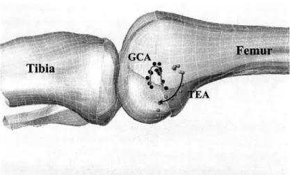
TKA - total knee arthroplasty. ... 47 Figure 4A: The figure show an anterior view of the femur and the two axes used in this
study to quantify knee kinematics. TEA transepicondylar axis; GCA -geom etric center... 57 Figure 4B: Axis definition: Two floating axes one based on the TEA and the other based
on the G C A ... 57 Figure 5: Axis differences: When comparing the axes anatomically, a large difference was noted between the positioning of the two axes on the medial side when compared to the positioning of the two axes on the lateral side. The small dotted circles represent the points on the far side of the bones... 58
Figure 6: Graphic representation of mean transepicondylar axis (TEA) vs. mean geometric center axis (GCA) medial translations. The medial condyle of the
TEA maintained a greater (+) posterior femoral translation throughout the
passive path when compared to the medial condyle of the GCA. Error bars represent one standard deviation from the mean (* p<0.05). ... 59 Figure 7: Graphic representation of mean transepicondylar axis (TEA) vs. mean
geometric center axis (GCA) lateral translations. The lateral condyle of the
TEA maintained a greater (+) posterior femoral translation throughout the
passive path when compared to the medial condyle of the GCA. Error bars represent one standard deviation from the mean (* p<0.05)... 60 Figure 8: Graphic representation of mean transepicondylar axis (TEA) vs. mean geometric center axis (GCA) tibial rotations. The GCA maintained a greater degree of internal (+) tibial rotation compared to the TEA throughout passive flexion. Error bars represent one standard deviation from the mean (*
p < 0 .0 5 )...6 1
Figure 9: Graphic representation of femoral translation on the medial side using the TEA and the GCA. The TEA showed monatomic posterior translation while the
GCA first translated anteriorly (<50') and then proceeded to translate
posteriorly ... . . 63
Figure 10: The figure shows the robotic testing system set up. The system includes the robotic manipulator, 6 degrees-of-freedom load cell, and the intact knee... 73
Figure 11: The figure outlines the transepicondylar axis which is the line connecting the insertion site of the medial and lateral collateral ligaments (LCL= lateral
collateral ligament; MCL= medial collateral ligament)... ... 73
Figure 12: Overall testing protocol for testing the biomechanics of intact knees. ACL = anterior cruciate ligament; PCL = posterior cruciate ligament. ... 74 Figure 13: Posterior femoral translation as a function of knee flexion on the passive path.
... 7 7
Figure 14: Internal tibial rotation as a function of knee flexion on the passive path... 78 Figure 15: The figure shows the posterior femoral translation (+) of the lateral and medial femoral condyles as a function of knee flexion. * denotes a p value less than 0 .0 5 ... . . 7 9
Figure 16: The figure illustrates the differential posterior femoral translation motion of lateral and medial condyles on the cross section of the tibia. The higher posterior translation of the lateral condyle compared to the medial condyle indicates internal tibial rotation. ... 80
Figure 17: In-situ forces of the ACL under various muscle loads... 81
Figure 18: In-situ forces of the PCL under various muscle loads... 82
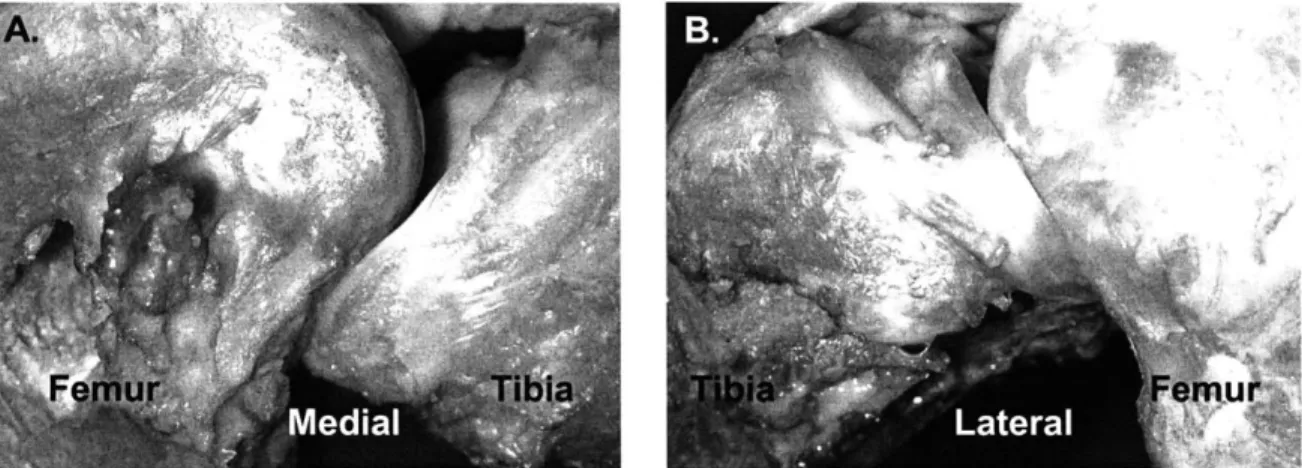
Figure 19: The position of the A) medial and B) lateral meniscus at high knee flexion
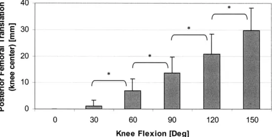
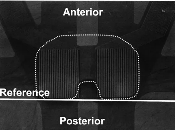
(1500)... 84 Figure 20: The position of the TekScan* film over the polyethylene liner... 104 Figure 21: Posterior (+) femoral translation (knee center) on the passive path for intact, conventional PCL-retaining, and conventional PCL-deficient TKAs as a function of flexion angles (* denotes p < 0.05). ... 106
Figure 22: Femoral translation (knee center) on the passive path for intact, conventional PCL-retaining, and conventional PCL-deficient TKAs as a function of flexion angles (* denotes p < 0.05). ... 107
Figure 23: Posterior (+) femoral translation (femoral rollback) of the knee under isolated quadriceps load; A) lateral femoral condyle; and B) medial femoral condyle.
... 1 0 9
Figure 24: Posterior (+) femoral translation (femoral rollback) of the knee under the combined quadriceps and hamstring load; A) lateral femoral condyle, and B) m edial fem oral condyle... 110
Figure 25: Posterior (+) femoral translation (femoral rollback) of the knee under the isolated hamstring load; A) lateral femoral condyle, and B) medial femoral co n dy le. ... 111 Figure 26: Internal tibial rotation of the knee under various muscle loads: A) isolated
quadriceps load, B) combined quadriceps and hamstrings load, and C) isolated ham strings load (* p<0.05)... 113
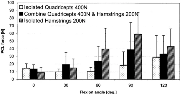
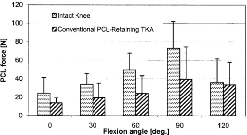
Figure 27: PCL forces in a conventional PCL-retaining TKA as a function on knee flexion under various m uscle loads... 115 Figure 28: A comparison of PCL forces in the intact knee and conventional
PCL-retaining TKA under combined muscle load. ... 116
Figure 29: Anterior (-) and posterior (+) femoral translation of the intact, conventional PCL-retaining TKA, and high flexion PCL-retaining TKA on the passive path.
Figure 30: Internal tibial rotation of the intact, conventional PCL-retaining TKA, and high flexion PCL-retaining TKA on the passive path... 118
Figure 31: The graph shows the posterior (+) femoral translation of the lateral femoral condyles as a function of knee flexion (* denotes p < 0.05). ... 119 Figure 32: The graph shows the posterior femoral translation of the medial femoral
condyles as a function of knee flexion (* denotes p < 0.05)... 121 Figure 33: The graph shows the differential motion between the lateral and medial
femoral condyles for the three knee states at selected flexion angles... 122 Figure 34: PCL forces in a high flexion PCL-retaining TKA as a function on knee flexion
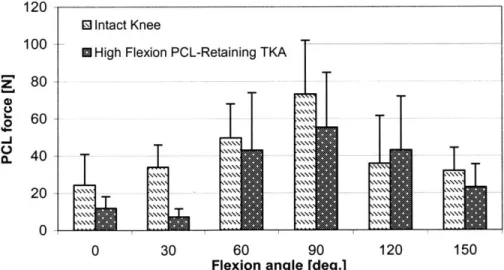
on the passive path and under combined 400N quadriceps and 200N ham strings load...123 Figure 35: A comparison of PCL forces in the intact knee and the high flexion
PCL-retaining TKA under combined muscle load. ... 123
Figure 36: Peak contact point on the A) medial and B) lateral femoral condyles for two TKA designs under combined muscle load (zero Y-axis represents the posterior edge of the polyethylene liner) CR = PCL-retaining ... 125 Figure 37: Contact area location of conventional PCL-retaining TKA (left) and high flexion PCL-retaining TKA (right) as a function of knee flexion at A) full extension, B) 300, C) 600, D) 900, E) 1200, F) 1350, and G) 1500... 128
Figure 38: Schematic illustration of the contact area of a typical specimen for a conventional PCL-retaining (NexGen CR) TKA (left) and a high flexion PCL-retaining (CR-Flex) TKA (right) at selected flexion angles under combined muscle load (contact value are in Table 1)... 128
Figure 39: A comparison of PCL forces in all three knee states under combined muscle load. Note that the conventional TKA was not tested at 150 ... 131 Figure 40: Posterior translation of the lateral and medial femoral condyles on the passive
path (* p<0.05). Lat. = lateral; Med. = Medial; PS = posterior-stabilized.... 151 Figure 41: Posterior translation of the lateral and medial femoral condyles under isolated
400N quadriceps load (* p<0.05). Lat. = lateral; Med. = Medial; PS =
posterior-stabilized...152
Figure 42: Posterior translation of the lateral and medial femoral condyles under combined 400N quadriceps and 200N hamstrings load (* p<0.05). Lat. = lateral; M ed. = M edial; PS = posterior-stabilized... 153
Figure 43: Posterior translation of the lateral and medial femoral condyles under isolate
200N hamstrings load (* p<0.05). Lat. a lateral; Med. = Medial; PS =
posterior-stabilized... 154 Figure 44: Posterior translation of the lateral and medial femoral condyles under isolate
200N hamstrings load (* p<0.05). Lat. a lateral; Med. = Medial; PS =
posterior-stabilized... 155 Figure 45: Overall testing protocol for high flexion fixed and mobile posterior-stabilized T K A experim ent. ... 162
Figure 46: Photograph shows the A) femoral component, B) fixed-bearing polyethylene liner, and C) mobile-bearing polyethylene liner used in this study... 164 Figure 47: Graphs show the posterior translation of the A) lateral and B) medial femoral condyles on the passive path... 165
Figure 48: Graphs show the posterior (+) translation of the A) lateral and B) medial femoral condyles under combined muscle load. ... 167
Figure 49: Graph shows the internal tibial rotation as a function of knee flexion on the p assiv e p ath . ... 16 8
Figure 50: Graph shows the internal tibial rotation as a function of knee flexion under com bined m uscle load... 169
Figure 51: At 900 of knee flexion, the polyethylene of the mobile bearing posterior-stabilized TKA reached the anterior stop... 171
Figure 52: Once the polyethylene reaches the tibial stop, polyethylene overhangs the tib ial tray ... 172
Figure 53: The figure shows the three main stages of the cam-spine... 176
Figure 54: The disengagement of the cam-spine in the fixed bearing posterior-stabilized TKA was observed at high knee flexion: A) anterior view and B) medial view.
... 17 6
Figure 55: The disengagement of the cam-spine in the mobile bearing posterior-stabilized TKA was observed at high knee flexion: A) medial view and B) lateral view, and C ) anterior view ... 177
Figure 56: The sizing and placement of the tibial tray. On the lateral side, the posterior edges of the tibial tray and the tibial bone are aligned. However, on the medial side, the tibial tray does not fully cover the medial face of the tibial b o n e ... 17 8
Figure 57: Moving the tibial tray posteriorly may provide greater contact area and improved stability at high knee flexion. ... 179
Figure 58: Knee model: A) sagittal image from x-ray, B) image after MATLAB* edge detection, and C) the final 3D m odel. ... 189
Figure 59: These figures show A) the selected points on the femur, and B) the selected points on the tibia, used in the gap analysis. C) The high flexion gap (HFG) was defined as the shortest distance between the femoral and the tibial bones
... 1 9 0
Figure 60: The flexion gap for both knees progressively decreased with increasing knee flexion (* denotes p <0.05 when the given flexion angle is compared to the sam e knee state at 900)... 19 1
Figure 61: The A) medial and B) lateral flexion gaps for both knees at selected flexion an g les... 19 2
List of Tables
Table 1. Reported range of flexion for various TKA designs [8] (Table adopted with permission from Lippincott Williams & Wilkins). ... 28
Chapter 1
INTRODUCTION
1.1 Motivations and Objectives
Approximately 16 million Americans suffer from osteoarthritis (OA) and more than 5 million American adults suffer from knee OA (American Academy of Orthopaedic Surgeons). OA is characterized by slowly progressive cartilage degeneration, a
thickening of the subchondral bone, the formation of osteophytes, and bone changes [1]. Patients with OA often suffer from pain and joint stiffness. In the case of severe OA, the disease can be debilitating by limiting patients from performing daily living activities as a result of severe reduction in joint range of motion. Total knee arthroplasty (TKA) was initially developed to alleviate pain in cases of severe OA of the knee and allowed patients to return to their daily activities. As the procedure evolved, the long-term success rate in terms of patient satisfaction has improved to in excess of 85% at 10-15 years follow-up [2-6]. Knee range of motion after TKA is considered an important variable in determining clinical outcome [7, 8]. Yet, the accomplishments achieved in restoration of knee motion and kinematics have not paralleled those of pain relief [9].
Attempts at improving knee flexion after TKA have remained of great interest among researchers.
The amount of knee flexion has been linked to functional outcome and activities of daily living [10]. For activities such as sitting on a chair, walking, and stair climbing, the required knee range of motion is limited to approximately -10' to 1000. However, knee flexion beyond 900 is essential and desired in many other day to day circumstances
[8]. Rowe et al [11, 12] reported that getting into a bath requires an average knee flexion
of 123.30 ± 14.1' and getting out of a tub requires an average knee flexion of 131.3 ± 14.3'. An individual typically needs between 1110 and 165' of knee flexion in order to squat, kneel, and sit cross-legged [10, 13, 14]. Weiss et al [15] surveyed 367 post TKA patients as to their interest in participating in sport activities after the surgery. The survey reveled that patients are interested in stretching exercise (56%), kneeling (52%) and gardening (50%) activities; yet patients find it very difficult to perform these activities after TKA. Low impact activities such as gardening, meditation, yoga, golf or a catcher in a softball game, often require knee flexion beyond 1500 (Figure 1) [9, 10]. In fact, "golf is a frequent form of exercise for the older population in whom TKAs are usually performed" [16] and to check the line for a putt on the green in golf requires that the individual be able to squat, which requires knee flexion of greater than 120' [9].
Figure 1. Selected examples of low impact activities that require high knee flexion: A. yoga and meditation, B. gardening, and C. catcher during a softball game.
The need of patients to return to their daily living activities after TKA may vary from person to person. In many Western countries, patients' choice in engaging in activities that require high knee flexion (>1200) is considered an additional benefit as these activities are not crucial to the patients' life. However, professions such as construction workers, farmers [17], and plumbers, highly depend on their ability to continue to work after TKA as a source of income. Patients whose movement is restricted after TKA may experience disability that would have both personal and economic consequences. The dilemma of limited knee flexion after TKA may be more apparent in the Far and Middle East countries as many activities that require knee flexion beyond 1200 are vital for the patients' daily function in these countries. For example, Japanese and Indian people squat in order to use "Eastern style toilets" [10]. Kneeling is a commonly used position for sitting, praying, or dining [10, 18]. Without the ability to flex beyond 1200, these activities will not be achievable and these patients' life will deviate from their cultural norm.
Although the human knee is capable of flexing more than 1500, contemporary TKAs rarely result in knee flexion greater than 1200 (Table 1) [8, 19-28]. The success of any total knee replacement system may be, in part, linked to its ability to optimally restore intact knee function. Current prosthetic designs and surgical techniques may not
meet the needs of patients who require high knee flexion for their daily activities. Several arthroplasty designs are available that incorporate modifications aimed at improving the post-operative knee range of flexion [29-31]. However, limited data are available on their function and potential advantages.
Table 1. Reported range of flexion for various TKA designs [8] (Table adopted with permission from
Lippincott Williams & Wilkins).
Study Follow-up (yr) Design No. of knees Mean flexion (degrees) (range)
Cruciate sacrificing
Goldberg et al. 9 Total condylar 109 95 (15-115)
Insall et al. 6.5 Total condylar 100 89 (no range reported)
Ranawat et al. 13.2 Total condylar 62 99 (65-120)
Cruciate substituting
Aglietti et al. 5.5 Insall-Burstein 73 96 (70-120)
Emmerson et al. 12.7 Kinematic stabilizer 109 98 (25-130)
Ranawat et al. 4.8 Press-Fit condylar 125 111 (75-135)
Cruciate retaining
Dennis et al. 11 Cruciate condylar 42 104 (76-120)
Lee et al. 9 Cruciate condylar 144 106 (no range reported)
Malkani et al. 10 Kinematic condylar 119 105 (±11)
Rosenberg et al. 3.5 Miller-Galante 116 105 (45-140)
As part of my Master's thesis, a robotic testing system was developed to investigate joint kinematics [32]. Since then, in vitro experimental models incorporating the robotic system have been used to investigate the biomechanics of the intact knee and various TKA designs throughout the entire range of flexion (full extension to 150' of flexion) [33-38]. Many of these experiments are described in detailed in this dissertation.
The overall goal of this work is to better understand the factors that limit the human knee joint from achieving higher degrees of flexion after TKA. In particular, the past several years have been utilized to answer the following questions:
1. How does the intact knee behave at high flexion angels (>1200)? What makes the knee so stable at extreme flexion angles? Which structure(s) guide(s) intact knee motion beyond 120'?
2. What is the role of the soft tissue structure (including posterior cruciate ligament (PCL), menisci, muscles, posterior soft tissue compression) on intact knee motion at high flexion angles?
3. Do contemporary TKA designs restore intact knee kinematics (femoral translation
and tibial rotation) from full extension (00) to full flexion (1500)? If not, to what extend do they restore the kinematics?
4. What is the function of the PCL in a cruciate retaining TKA, particularly at high knee flexion?
5. What is the function of the cam-spine in a posterior-stabilized TKA, particularly at high knee flexion?
6. What is the effect of soft tissue compression on the motion of the reconstructed
knee(s) at flexion angles beyond 1200?
7. Is kinematics data sufficient to describe the performance of a given TKA design?
How does contact mechanics, predominantly at high knee flexion, comes into play?
8. What happens to the flexion gap with increasing flexion angles to both the intact
and the reconstructed knees?
In this work, flexion angles beyond 1200 are considered to be high flexion angles. The robotic model in conjunction with clinical studies provides an understanding of the limitations of contemporary knee designs in achieving higher degrees of knee flexion.
This may lead to the refinement of existing designs and development of newer prostheses that will enhance the range of flexion that is achievable following TKA.
1.2 Organization
The work in this dissertation is divided into two main sections. The first deals with the understanding of intact knee kinematics and kinetics throughout the full range of motion (00 - 1500). The second investigates various conventional TKA designs and
compares their performance to that of the intact knee.
The text is organized sequentially. Chapter 2 describes the steps taken to adjust the robotic testing system for testing intact and reconstructed knees on the same specimen. Chapter 3 reports a description of different coordinate systems and their effect on the kinematics. This is a critical chapter as it provides the reader with a comprehensive background to better understand the differences that exist in the literature regarding the different studies. Chapter 4 includes a detailed analysis of the intact knee biomechanics from full extension to 1500 of flexion. In addition, a literature review of relevant work both on intact knee kinematics and ligament force is presented. In Chapters 5 and 6, the reader can find a description of the biomechanics of two contemporary TKA designs and their compression in relation to the intact knee. Chapter
7 includes a preliminary analysis of the flexion gap in high knee flexion. The flexion gap
is thought to be a limiting factor in allowing high knee flexion. The final chapter presents the overall results of this project as well as suggestions for future directions in TKA design and performance.
The dissertation is based on the following papers:
1. "Cruciate-retaining and cruciate-substituting total knee arthroplasty: an in vitro comparison of the kinematics under muscle loads", Li G, Zayontz S, Most E, Otterberg E, Sabbag K, Rubash HE., J Arthroplasty. 2001 Dec;16(8 Suppl
1):150-156.
2. "Biomechanics of posterior-substituting total knee arthroplasty: an in vitro study", Li G, Most E, Otterberg E, Sabbag K, Zayontz S, Johnson T, Rubash H, Clin Orthop. 2002 Nov;(404):214-225.
3. "Femoral rollback after cruciate-retaining and stabilizing total knee arthroplasty",
Most E, Zayontz S, Li G, Otterberg E, Sabbag K, Rubash HE, Clin Orthop. 2003 May;(410):101-113.
4. "The Kinematics of Fixed- and Mobile-Bearing Total Knee Arthroplasty", Most
E, Li G, Schule S, Sultan P, Park SE, Zayontz S, Rubash H, Clin Orthop. 2003
Nov; (416):197-207.
5. "Optimizing Flexion after Total Knee Arthropaslty: Advances in Prosthetic Design", Sultan P, Most E, Li G, Rubash E, Clin Orthop. 2003 Nov;
(416):167-173.
6. "Effect of the Posterior Cruciate Ligament on Posterior Stability of the Knee in High Flexion" G. Li, E. Most, L. E. DeFrate, J. F. Suggs, T. J. Gill, H. E. Rubash, Submitted to JBJS May 2003.
7. "Kinematics of the knee at high flexion angles: an in vitro investigation", G. Li, S. Zayontz , L. E. DeFrate, E. Most, J. F. Suggs, H. E. Rubash, Journal of Orthopaedic Research, 2004, Jan 22(1): 90-95.
8. "An Evaluation of Knee Kinematics with a High Flexion Posterior-Stabilized Total Knee Arthroplasty Using an in vitro Robotic Experimental System" G. Li;
E. Most; P. Sultan; S. Schule; S. Zayontz.; H. Rubash, Submitted to JBJS July 2003.
9. "Sensitivity of the Knee Joint Kinematics Calculation to Selection of Flexion Axes", E Most; J Axe; H Rubash; G Li, Submitted to J biomech August 2003.
10. "Kinematics Analysis of a Conventional and a High-Flexion Cruciate Retaining Total Knee Arthroplasties: An In-vitro Investigation", Most E, Li G, Sultan P, Park SE, Rubash HE, Submitted to J Arthroplasty.
11. "A Comparison of the Contact Behavior between a Conventional and a
High-Flexion Cruciate Retaining Total Knee Arthroplasty", Most E, Li G, Papannagari, R, Sultan P, Park SE, Rubash HE, to be submitted.
1.3 References
1. Silver, F., G. Bradica, and A. Tria, Structure and Biomechanics ofArticular
Cartilage, in The Adult Knee, J. Callaghan, et al., Editors. 2003, Lippincott
Williams & Wilkins: Philadelphia. p. 105-122.
2. Duffy, G.P., R.T. Trousdale, and M.J. Stuart, Total knee arthroplasty in patients 55 years old or younger. 10- to 17-year results. Clin Orthop, 1998(356): p. 22-7.
3. Gill, G.S. and A.B. Joshi, Long-term results of retention of the posterior cruciate
ligament in total knee replacement in rheumatoid arthritis. J Bone Joint Surg Br,
2001. 83(4): p. 510-2.
4. Meding, J.B., M.A. Ritter, and P.M. Faris, Total knee arthroplasty with 4.4 mm of
tibial polyethylene: 10-year followup. Clin Orthop, 2001(388): p. 112-7.
5. Pavone, V., et al., Total condylar knee arthroplasty: a long-term followup. Clin Orthop, 2001(388): p. 18-25.
6. Schai, P.A., T.S. Thornhill, and R.D. Scott, Total knee arthroplasty with the PFC
system. Results at a minimum of ten years and survivorship analysis. J Bone Joint
Surg Br, 1998. 80(5): p. 850-8.
7. Maloney, W.J. and D.J. Schurman, The effects of implant design on range of
motion after total knee arthroplasty. Total condylar versus posterior stabilized total condylar designs. Clin Orthop, 1992(278): p. 147-52.
8. Li, G., et al., Improving flexion in total knee arthroplasty, in The Adult Knee, J. Callaghan, et al., Editors. 2002, Lippincott Williams & Wilkins: Philadelphia. p.
9. Sultan, P., et al., Optimizing Flexion After Total Knee Arthroplasty: Advances in
Prosthetic Design. Clin Orthop, 2003.
10. Mulholland, S.J. and U.P. Wyss, Activities of daily living in non-Western
cultures: range of motion requirements for hip and knee joint implants. Int J
Rehabil Res, 2001. 24(3): p. 191-8.
11. Rowe, P.J., et al., Knee joint kinematics in gait and other functional activities
measured using flexible electrogoniometry: how much knee motion is sufficient for normal daily life? Gait Posture, 2000. 12(2): p. 143-55.
12. Myles, C.M., et al., Knee jointfunctional range of movement prior to and
following total knee arthroplasty measured using flexible electrogoniometry. Gait
Posture, 2002. 16(1): p. 46-54.
13. Hefzy, M.S., B.P. Kelly, and T.D. Cooke, Kinematics of the knee joint in deep
flexion: a radiographic assessment. Med Eng Phys, 1998. 20(4): p. 302-7.
14. Nagura, T., et al., Mechanical loads at the knee joint during deep flexion. J Orthop Res, 2002. 20(4): p. 881-6.
15. Weiss, J.M., et al., What functional activities are important to patients with knee
replacements? Clin Orthop, 2002(404): p. 172-88.
16. Mallon, W.J. and J.J. Callaghan, Total knee arthroplasty in active golfers. J
Arthroplasty, 1993. 8(3): p. 299-306.
17. Trousdale, R., et al., Case Challenges in Hip & Knee Surgery: Knee Challenges:
What Would You Do? Orthopedics, 2002. 25(9).
18. Koshino, T., et al., Increase in range of knee motion to obtainfloor sitting after
19. Aglietti, P., R. Buzzi, and A. Gaudenzi, Patellofemoralfunctional results and complications with the posterior stabilized total condylar knee prosthesis. J
Arthroplasty, 1988. 3(1): p. 17-25.
20. Dennis, D., et al., Posterior cruciate condylar total knee arthroplasty: average
11-yearfollowup evaluation. Clin Orthop, 1992. 281: p. 168-176.
21. Emmerson, K.P., C.G. Moran, and I.M. Pinder, Survivorship analysis of the
Kinematic Stabilizer total knee replacement: a 10- to 14-year follow-up. J Bone
Joint Surg Br, 1996. 78(3): p. 441-5.
22. Goldberg, V.M., et al., Use of a total condylar knee prosthesis for treatment of
osteoarthritis and rheumatoid arthritis. Long-term results. J Bone Joint Surg Am,
1988. 70(6): p. 802-11.
23. Insall, J.N., et al., The total condylar knee prosthesis in gonarthrosis. A five to
nine-year follow-up of the first one hundred consecutive replacements. J Bone
Joint Surg Am, 1983. 65(5): p. 619-28.
24. Insall, J.N., et al., Total knee arthroplasty. Clin Orthop, 1985(192): p. 13-22.
25. Lee, J.G., et al., Review of the all-polyethylene tibial component in total knee
arthroplasty. A minimum seven-year follow-up period. Clin Orthop, 1990(260): p.
87-92.
26. Malkani, A.L., et al., Total knee arthroplasty with the kinematic condylar
prosthesis. A ten- yearfollow-up study. J Bone Joint Surg Am, 1995. 77(3): p.
423-31.
27. Rand, J.A., Comparison of metal-backed and all-polyethylene tibial components
28. Ranawat, C.S., C.P. Luessenhop, and J.A. Rodriguez, The press-fit condylar
modular total knee system. Four-to-six-year results with a posterior-cruciate-substituting design. J Bone Joint Surg Am, 1997. 79(3): p. 342-8.
29. Yamazaki, J., et al., Hy-Flex H total knee system and range of motion. Arch Orthop Trauma Surg, 2002. 122(3): p. 156-60.
30. Akagi, M., et al., The Bisurface total knee replacement.: a unique design for
flexion. Four- to-nine-year follow-up study. J Bone Joint Surg Am, 2000.
82-A(11): p. 1626-33.
31. Zimmer, I., NexGen LPS-Flex Design Rationale: Warsaw, IN.
32. Most, E., Development of a 6-DOF Robotic Test System for Studying the
Biomechanics of Total Knee Replacement, in Department of Mechanical Engineering. 2000, June, MIT: Cambridge.
33. Li, G., et al., Cruciate-retaining and cruciate-substituting total knee arthroplasty: an in vitro comparison of the kinematics under muscle loads. J Arthroplasty,
2001. 16(8 Suppl 1): p. 150-6.
34. Li, G., et al., Biomechanics ofposterior-substituting total knee arthroplasty: an in
vitro study. Clin Orthop, 2002(404): p. 214-25.
35. Most, E., et al., Femoral rollback after cruciate-retaining and stabilizing total knee arthroplasty. Clin Orthop, 2003(410): p. 101-13.
36. Gill, T.J., et al., The biomechanical effect ofposterior cruciate ligament
reconstruction on knee
joint
function. Kinematic response to simulated muscle loads. Am J Sports Med, 2003. 31(4): p. 530-6.37. Li, G., et al., Determination of optimal graft lengths for posterior cruciate
ligament reconstruction--a theoretical analysis. J Biomech Eng, 2003. 125(2): p.
295-9.
38. Li, G., et al., Biomechanical consequences of PCL deficiency in the knee under
simulated muscle loads--an in vitro experimental study. J Orthop Res, 2002.
Chapter 2
DEVELOPMENT OF THE ROBOTIC
TESTING PROTOCOL FOR
STUDYING THE BIOMECHANICS OF
INTACT AND RECONSTRUCTED
KNEES
2.1 Motivations and Objectives
Total knee arthroplasty (TKA) is performed, in part, to allow patients to return to their pre-operative activities by restoring their normal knee function. Failure to mimic intact knee kinematics is thought to contribute to implant loosening and polyethylene wear, which ultimately lead to revision [1].
Several methods for studying knee kinematics are reported in the literature [2-18]. In vivo kinematics measurements include the use of optical markers, attached to the skin
or directly on the bone, to track the relative motion of the tibia with respect to the femur [2-5, 15, 16]. Lafortune [16] described the angular and linear three dimensional knee kinematics using intra-cortical pins fixed directly on the femoral and tibial bones during walking activity. The limiting factors in this study include the limited degree of freedom, no high flexion information, and the inability to directly compare different knee stages on the same patient. Andriacchi et al [2] developed the point cluster technique to measure the six degrees of freedom motion of a knee. The markers are uniformly distributed on the subject's soft tissue limbs (i.e. thigh and shank) and their motion is tracked by an optoelectronic digitizer. Nagura et al [3] used six retro-reflective markers, an opto-electronic system, and a force plate to analyze the mechanical loads in human knee joints exhibited during four different activities, including deep kneeling. They concluded that at high knee flexion, the knee experiences large forces and moments. The limitations of their study include neglecting the contact force between the thigh and the calf, and the inability to directly compare the pre- and post-operative conditions on the same subject.
In vivo investigations provide us with insightful data regarding the motion (kinematics) of the knee either before or after TKA. However, rarely do we know the preoperative kinematics for the same patient undergoing TKA and, therefore, a direct in-vivo comparison between the normal and reconstructed knee cannot be determined. Consequently, it is vital to perform in vitro investigation where by the healthy knee serves as its own control for any TKA performed.
Most in vitro testing systems provide useful information with only one aspect of research such as limited degrees of freedom kinematics, or limited range of flexion.
Often, high knee flexion (>120') cases are excluded [6-9, 13]. Lewis at al [13] developed a system that measures three dimensional joint motion and ligament forces using a combination of instrumented spatial linkage (ISL) system, buckle transducers, and pneumatic load apparatus. They reported a large anterior cruciate ligament force
(90N) at 20 degrees of knee flexion. No information was given in regards to higher
flexion angles. Kirstukas, Lewis and Erdman [8, 9] designed a six degrees ISL system to measure joint motion. However, they reported that limited resolution of the devices that monitor the position of the linkage joints exists. The Oxford Knee Rig (OKR) has been used by several groups to investigate the movement of the knee joint and patellofemoral force in six degrees or freedom [10, 17-20]. Wilson et al [17] used fifteen human cadaver knees to study the relative motion of the tibia with respect to the femur for the unloaded knee using the OKR and an electromagnetic tracking system from full extension to 1000 of flexion. They reported that with increasing knee flexion, coupled tibial rotation and ab/adduction occurred.
Recently, a robotic testing system was introduced to examine the six degree of freedom knee kinematics [21-26]. Rudy et al [21, 23-25] developed a robotics-based joint testing system that offers the ability to control both the paths of motion as well as the acting forces. The system provides not only the measurement of structural properties, but also the ability to store and repeat the six degrees-of freedom motion under different loading conditions. In response to external loads, the robot can learn the complex motion of the knee specimen and can reproduce these motions in subsequent tests. Their system was used extensively to study intact knee kinematics and ligament forces on the passive path and under muscle load conditions for knee flexion up to 120' [22, 27-32].
Most [26] adopted the robotic testing system and expanded the concept to allow for in-vitro testing of intact and TKA knees on the same specimen. The test system is composed of a six degree-of-freedom robotic manipulator (Kawasaki UZ1 50®, Kawasaki Heavy Industry, Japan) and a six degree-of-freedom load cell (JR3 DSP-based force sensor receiver, JR3 Inc., Woodland, CA). A control algorithm, written to account for the coupling effects of the different degree-of-freedom of the knee, was developed. Using a personal computer, the robot and the load cell were controlled to allow for both displacement and force modes. Using the system, the kinematics of knees, the tibio-femoral contact, and soft tissue forces can be measured. Detailed description can be found in Most Master's thesis [26]. This chapter provides the principles, specimen installation, and detailed testing protocol used in the different studies through out this dissertation work.
2.2 Coordinate System Establishment
The general term "knee kinematics" usually refers to rotation about and translation along defined coordinate axes [33]. It is therefore critical to define clear and concise coordinate systems to both the tibia and the femur such that the relative motion between the two bones can be quantified. Through the entire development, the femoral and tibial bones are to be considered rigid bodies.
The knee coordinate system is constructed by digitizing (MicroScribe 3DX* Digitizer, Immersion Corporation, San Jose, CA) several anatomic points on the knee. The longitudinal axis of the tibia (x) is built by connecting two points of the tibial shaft parallel to the posterior cortex in the longitudinal direction of the tibia (Figure 2A). The
transepicondylar (medial-lateral) axis of the femur (y) is defined as a line connecting the most prominent point within the lateral collateral ligament insertion site and the most prominent anterior to the sulcus point within the insertion site of the medial collateral ligament (Figure 2B) [34, 35]. By taking the cross product of these two axes, the
anterior-posterior axis of the knee (z) is created (Figure 2A). The origin of the system (knee center) is chosen as the midpoint of the transepicondylar line (Figure 2B).
The femoral coordinate system and the tibial coordinate system coincide with each other at full extension (initial position) under no load condition. Thus, only one coordinate system is needed to be defined initially.
The knee specimen is aligned so that the load cell can measure three force and three moment components along and about a cartesian coordinate system. As the knee responds to external loads, the tibial coordinate system moves with the tibia. At that point, the coordinate system of the femur no longer coincides with the coordinate system of the tibia. Therefore, the translation vector and the rotation matrix of the tibia with respect to the femur must be evaluated to determine the knee kinematics. An Euler sequence (y-z-x) was adopted to describe the tibial rotation. A derivation of the
Figure 2A: The figure shows the installation of the specimen and the construction of the coordinate system. For purposes of demonstration only, all soft tissues were removed.
Medial
Knee Center
Lateral
Figure 2B: The figure outlines on an anterior view of a femur and the transepicondylar axis.
2.3 Specimen Preparation and Installation
A minimum of eight post-mortem human knee specimens are used in each study (individual studies are described in upcoming chapters). Prior to testing, each specimen
is thawed over night at room temperature. Each knee includes approximately 25cm of bone above and below the joint line, leaving all soft tissues (capsule, ligaments, menisci, posterior capsule, skin, fat, and muscles) around the knee joint intact. The fibula is fixed to the tibia in an anatomical position by a cortical bone screw.
Each knee is manually examined and flexed through its entire range of flexion to assure suitable range of flexion for a given test. Each knee is also x-rayed in both anterior/posterior and medial/lateral views to verify that the knee is healthy with no prior injuries or surgeries. Knees that do not follow these guidelines are excluded from the study.
Both femoral and tibial shaft ends are exposed and potted, using polymethylmethacrylate (PMMA), to enable secured mounting of the specimen on the robotic system. During the experiment, the femur cylinder is rigidly fixed to a specially designed clamp that allows 6 degrees-of-freedom positioning of the femur relative to the robotic system base (Figure 2A). The tibial cylinder is rigidly fixed to the robot arm through the load cell. This set-up allowed the tibia to freely move with the robot arm in 6 degrees-of-freedom about the femur. To avoid dehydration of the specimen, 0.9% saline was regularly sprayed over the specimen.
Each experiment includes the simulation of an unloaded knee state (passive path) as well as loaded knee state (under muscles loads). The later is performed using a pulley and weight system [36]. Prior to each experiment, the tendons of each muscle are manually isolated and a rope is sutured to each one by means of polyester sutures (Ethibond Excel, Ethicon Inc, Johnson & Johnson). During a given experiment, weights are hung from the free end of the rope to simulate muscle forces. Muscular forces of the
quadriceps and the medial and lateral hamstrings (semitendinosus/ semimembranosus and biceps femoris) and their co-contraction are simulated in each study.
2.4 Testing Protocol
The robotic testing system allows for multiple tests on the same specimen thereby eliminating inter-specimen variations. A general testing protocol is presented in Figure 3. Prolonged testing of soft tissue may lead to tissue degradation, therefore, only a segment of the protocol can be performed during a given experiment. Throughout this thesis, several experiments were performed to answer all the questions raised in the motivation and objective chapter. In every experiment, the intact knee was tested first and served as the baseline reference for the remainder of the study. A detailed description of each test will be given in the following chapters. Each test includes the determination of the passive path and the kinematics due to the application of various muscle loads.
2.4.1 Passive Path Determination
The passive path is the characteristic behavior of the knee motion determined by the articular geometry and the surrounding soft tissue constraints. In our studies, a passive position at a specific flexion angle is defined as the position of the knee where the knee carries minimal load under no external load. After the knee is mounted onto the joint testing system, a series of passive positions were defined at one-degree increments between 00 and 1500 of flexion. At each degree, knee positions for the remaining 5
degrees of freedom were determined such that the residual forces and moments at the knee joint center (midpoint of the transepicondylar line) were minimized (<5 N and 0.5
N-m for normal knees, respectively). These pre-determined passive positions represented the relative position of the tibia with respect to the femur at which the joint carried a minimal load. This series of passive positions formed a passive path between full extension to full flexion (1500). This path was then used as the reference position for the subsequent application of simulated physiological loads during testing.
2.4.2 Kinematics under Various Muscle Loads
Simulation of quadriceps and hamstring muscles and their co-contraction was performed using a pulley system, as previously described. Muscular forces of the quadriceps and the medial and lateral hamstrings (semitendinosus/ semimembranosus and biceps femoris) at 2:1 ratio are simulated in each study and at given flexion angles (00,
300, 600, 900, 120* and 150'). In general, three muscle loads are applied as follows: (1) an isolated quadriceps force of 400 N; (2) a combined quadriceps and hamstrings load (400 N and 200 N, respectively); and (3) an isolated hamstring force of 200 N. When a knee reaches a selected flexion angle along its passive path, muscle loading is then applied. At this point, the tibia is able to move along the remaining 5 degrees of freedom until reaching an equilibrium position where the applied load is balanced by the constraint forces generated inside the knee joint. The new knee position is then recorded
by the robotic manipulator. The test is repeated at each selected flexion angle for all the
Install
Int t k ... ...
Intact nee Passive Path
... Kinematics
... K in... m at...s . Passive Path Test
Kinematics Intact knee..-.--.-.-. ---...--.
Muscle Load(s)
... ... Kinem atics
K...m....
M uscle Load(s) cut -...
Kinematics ACL Passive Path
Force Muscle Load(s):
mKinematics ...:.T.s..CR TKA.-..-.. MPassive : Path i neF ar c sD..ign... M... Kinematicss us P s e Past :S T A... .--... .---...--Kinematics Design Muscle Load(s) re PCL Remove Knee Kinematics Force From the Robot
Figure 3: A detailed flow chart describing several scenarios for testing a single healthy specimen using the robotic system. ACL = anterior cruciate ligament; PCL = posterior cruciate ligament; CR = cruciate
retaining; PS - posterior stabilized; TKA = total knee arthroplasty.
2.4.3 Ligament and Soft Tissue Force Measurements
Once the passive path (Upasive) and the kinematics under various muscle loads (Umuscle) are determined the forces in the different ligaments and soft tissue can be measured by the principle of superposition [21, 22, 26]. The protocol in Figure 3 outlines the procedure. For example, to measure the in situ forces in the anterior cruciate ligament (ACL), the robotic testing system replays the pre-recorded kinematics (Upasive and Umuscie) and the load cell system measures the corresponding forces in the ACL (F1 ACL-passive and F1 ACL-muscle). The ACL is then resected and the knee kinematics (Upasive
ACL resection (F2 ACL-passive and F2ACL-muscle). According to the principle of superposition
[21, 22, 26], the difference between the forces measured before and after resecting the
ACL represent the ACL forces:
ACL forces on the passive path = F2ACL-passive - F1 ACL-passive
ACL forces under combined muscle loads = F2ACL-muscle - F1 ACLmuscle
This procedure can be followed for every ligament and soft tissue as long as only one structure is being measured at a time.