Publisher’s version / Version de l'éditeur:
Journal of Applied Electrochemistry, 40, Feb 2, pp. 247-256, 2010-02-01
READ THESE TERMS AND CONDITIONS CAREFULLY BEFORE USING THIS WEBSITE.
https://nrc-publications.canada.ca/eng/copyright
Vous avez des questions? Nous pouvons vous aider. Pour communiquer directement avec un auteur, consultez la
première page de la revue dans laquelle son article a été publié afin de trouver ses coordonnées. Si vous n’arrivez pas à les repérer, communiquez avec nous à [email protected].
Questions? Contact the NRC Publications Archive team at
[email protected]. If you wish to email the authors directly, please see the first page of the publication for their contact information.
NRC Publications Archive
Archives des publications du CNRC
This publication could be one of several versions: author’s original, accepted manuscript or the publisher’s version. / La version de cette publication peut être l’une des suivantes : la version prépublication de l’auteur, la version acceptée du manuscrit ou la version de l’éditeur.
For the publisher’s version, please access the DOI link below./ Pour consulter la version de l’éditeur, utilisez le lien DOI ci-dessous.
https://doi.org/10.1007/s10800-009-9998-8
Access and use of this website and the material on it are subject to the Terms and Conditions set forth at
Theoretical and experimental study of galvanic coupling effects between carbon steel and stainless steels
Qian, S. Y.; Qu, D.
https://publications-cnrc.canada.ca/fra/droits
L’accès à ce site Web et l’utilisation de son contenu sont assujettis aux conditions présentées dans le site LISEZ CES CONDITIONS ATTENTIVEMENT AVANT D’UTILISER CE SITE WEB.
NRC Publications Record / Notice d'Archives des publications de CNRC:
https://nrc-publications.canada.ca/eng/view/object/?id=6fdf4de9-e9e0-452d-987e-ef7d3a4160f5 https://publications-cnrc.canada.ca/fra/voir/objet/?id=6fdf4de9-e9e0-452d-987e-ef7d3a4160f5
http://www.nrc-cnrc.gc.ca/irc
T he ore t ic a l a nd e x pe rim e nt a l st udy of ga lva nic c oupling e ffe c t s be t w e e n c a rbon st e e l a nd st a inle ss st e e ls
N R C C - 5 3 2 3 6
Q i a n , S . Y . ; Q u , D .
F e b r u a r y 2 0 1 0
A version of this document is published in / Une version de ce document se trouve dans:
Journal of Applied Electrochemistry, 40, (2), February, pp. 247-256, DOI:
10.1007/s10800-009-9998-8
The material in this document is covered by the provisions of the Copyright Act, by Canadian laws, policies, regulations and international agreements. Such provisions serve to identify the information source and, in specific instances, to prohibit reproduction of materials without written permission. For more information visit http://laws.justice.gc.ca/en/showtdm/cs/C-42
Les renseignements dans ce document sont protégés par la Loi sur le droit d'auteur, par les lois, les politiques et les règlements du Canada et des accords internationaux. Ces dispositions permettent d'identifier la source de l'information et, dans certains cas, d'interdire la copie de documents sans permission écrite. Pour obtenir de plus amples renseignements : http://lois.justice.gc.ca/fr/showtdm/cs/C-42
Theoretical and experimental study of galvanic coupling effects between
carbon steel and stainless steels
S. Qian • D. Qu
Abstract
The use of stainless steel in high corrosion-risk areas represents a viable option for reducing the life-cycle cost and extending the service life of concrete structures. However, the possible galvanic corrosion between it and carbon steel continues to be a concern. In this paper the galvanic coupling behaviours of carbon steel and three different stainless steels were investigated in simulated pore solutions and concrete specimens. The results showed that the oxygen reduction reaction was much lower on stainless steel than on passive carbon steel, leading to a lower galvanic coupling current between stainless steel and corroding carbon steel than that between passive and corroding carbon steels. However, rust contamination of stainless steel was found to increase galvanic coupling corrosion on carbon steel.
Keywords: corrosion; galvanic coupling; reinforcing steel; chlorides; carbon steel; stainless steel;
S. Qian ( )
Urban Infrastructure, Institute for Research in Construction, National Research Council Canada, Ottawa, Ontario, Canada, K1A 0R6
e-mail: [email protected]
D. Qu
Department of Advanced Material Chemistry, College of Science & Technology, Korea University Sejong Campus Jochiwon, Chungnam Korea, 339-700
1 Introduction
The corrosion of steel reinforcement in concrete structures of highway bridges and parking garages can bring about major problems in terms of reduced safety and serviceability for the structures as well as increased rehabilitation costs. Stainless steel has been used to minimize reinforcement corrosion in many structures in the last 20 years due to its superior corrosion resistance. The use of this reinforcement, however, is still limited, partially because of its high initial cost [1]. A potential economical approach is to use stainless steel in the areas of the structure that are most vulnerable to aggressive conditions and corrosion (e.g. the top reinforcing steel mat of a deck, lower section of a pier or a splash zone). This will significantly extend the service life of a concrete structure with only a slight increase in initial cost. This approach can also be used in the repair of deteriorated reinforced concrete structures. While there has been considerable interest in this approach, concerns about galvanic corrosion when dissimilar metals are in direct (electrical) contact with each other in concrete structures have prevented its widespread application. As a result, engineers are hesitant to use stainless steel (SS) and carbon steel (CS) in the same concrete structure.
At present, limited studies have been published and those that have presented controversial results and conclusions. For instance, Knudsen et al. [2, 3] and Klinghoffer et al. [4] suggested that using CS with SS did not increase the risk of corrosion of CS as long as both metals were in a passive condition. This conclusion was also reached by Cochrane [5], Pérez-Quiroz [6] and Abreu et al [7]. Bertolini and co-workers [8-11] conducted their experiments on concrete specimens and concluded that the use of SS in connection with CS did not increase the risk of corrosion of passive CS. They stated that when both CS and SS are in the passive condition, the galvanic coupling current did not produce appreciable effects, since these two
types of steel had almost identical corrosion potentials. Active CS coupled with SS can increase the corrosion rate of active CS reinforcement in chloride contaminated concrete, however this increase is no worse than the coupling between active and passive CS, which always surrounds the active CS. This conclusion was supported by the results obtained in electrochemical cells and in concrete specimens by Qian et al. [12]. Hope [13] made a similar finding from his investigations, indicating that high and potentially damaging corrosion rates would arise in galvanically coupled CS and SS 316 or 2205 if the concrete surrounding the CS became chloride contaminated or carbonated. These corrosion rates were likely to be similar to, or somewhat less than, the corrosion rates, which would develop if CS alone was used. Webster [14], on the other hand, found that galvanic corrosion could take place if two different metals were electrically connected. He suggested that it would be necessary to isolate the electron transfer path between the anode and cathode to prevent corrosion damage due to galvanic coupling. Seibert [15] asserts that coupling CS with SS reinforcement is inadvisable, as galvanic coupling will initiate corrosion of the CS. It is very important to note that all the published results were only focused on the investigation of the galvanic coupling between clean SS and CS. The significant effect of rust contamination on increasing galvanic coupling corrosion has never been reported.
In this paper, the galvanic coupling behavior between CS and SS, including 304LN, 316LN and 2205 were investigated in both electrochemical cells containing saturated calcium hydroxide [Ca(OH)2] solution and concrete specimens inside an environmental chamber. Sodium
chloride (NaCl) was introduced to the solution during the experiment or premixed in the concrete to simulate aggressive environmental conditions in the field. The galvanic coupling currents between corroding CS and SS were measured and compared to those between corroding CS and passive CS, which always surrounds the corroding area in the field. Theoretical considerations
and analysis of galvanic coupling effects on both anode and cathode are provided. A quantitative calculation of the corrosion rate changes on corroding CS as a result of galvanic coupling was performed. The galvanic behavior between passive CS and SS was also studied to examine whether this coupling could initiate the corrosion of CS. An important effect of rust-contaminated SS (originating from contact with corroded CS) on increasing the galvanic coupling current was examined and recommendations to avoid this effect are provided.
2 Experimental
The electrodes used in the electrochemical cells for the investigation were made from the same batch of steel bars as those used in the concrete specimens, including CS and three types of SS, 2205, 304LN and 316LN. The steel electrodes were machined into two sizes: (1) small samples of 15 mm length and 9.4 mm diameter; and (2) large samples of 70 mm length and 12.5 mm diameter. The samples of CS and SS rebar were connected by steel rods as electric conductors and then embedded in epoxy resin leaving a fixed area of steel surface (0.7 cm2 and
28.6 cm2, respectively, for the two different sample sizes) exposed to the solution. The samples
were final polished with #600 silicon-carbide papers, degreased by acetone and de-ionized water before being immersed in saturated Ca(OH)2 solution with a pH of 12.6 for a week. A solution of
saturated Ca(OH)2 or saturated Ca(OH)2 + 3% NaCl were used for the experiments. De-ionized
water (≥ 18.2 MΩ cm, Milli-Q) was used to prepare the solution, while high purity argon and oxygen were used in some experiments to purge or increase, respectively, the content of oxygen in the solution.
The electrochemical experiments consisted of cyclic voltammetry, linear polarization, potential dynamic, AC impedance and galvanic coupling measurements. All tests (except the galvanic coupling measurements) were conducted in three-compartment electrochemical cells. The working electrode was the steel sample, while the counter electrode was made of platinum foil or mesh. The reference electrode was a saturated calomel electrode (SCE). A Luggin capillary was used to reduce the IR drop. The Cyclic voltammetry, linear polarization and potential dynamic measurements were carried out using a Solartron SI 1287 Electrochemical Interface or Solartron 1480 MultiStat, which was controlled by a PC computer using Corr-Ware software. The AC impedance measurements were performed by a Solartron SI 1287 Electrochemical Interface coupled with a SI 1260 HF Frequency Response Analyzer (FRA) and controlled by a PC computer with Zplot and Zview software.
Cyclic voltammograms were measured in the potential range of –1.2 V to +0.5 V (initiated from an open circuit potential) with a scan rate of 20 mV s-1. Potential dynamic tests
were measured from the open circuit potential to –0.65 V with a scan rate of 0.1 mV s-1. The
electrochemical polarization resistance (Rp) and the corrosion rate (Icorr) of the reinforcing steel
were determined using the linear polarization technique in the electrochemical cell. The potential of the steel electrode was scanned at a slow rate of 0.01 mV s-1 in the range of ±10 mV around
the corrosion potential, Ecorr.
The galvanic coupling experiments were carried out using an apparatus consisting of two cells connected by a salt-bridge. The galvanic coupling current was measured by connecting the two metals (having ratio of 1:1 in surface area and placed in each cell) using a Keithley 485 Picoammeter operated by a PC computer using VEE Pro software. The salt bridge was made of a U-shaped glass tube with an internal diameter of 9.4 mm. The two ends of the U-shaped glass
tube were sealed by a Celgard® 2500 microporous membrane to prevent solution flow and
reduce the rate of chloride ion diffusion. The glass tube was filled with a saturated Ca(OH)2
solution with 3% NaCl.
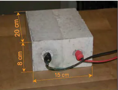
Concrete specimens for the galvanic coupling tests were made of CSA type 10 Portland cement (by mass, consisting of at least two-thirds calcium silicate, with the remainder containing aluminum oxide, iron oxide and other oxides) with a weight ratio of water : cement : sand : aggregate = 0.5 : 1 : 2 : 3. Quantities of 0%, 1.5% or 3.5% of chloride ions by weight of cement were dissolved in water and added to the concrete mixtures. Two rebars with a diameter of 16 mm were embedded in parallel in the concrete specimens, which had dimensions of 20 cm x 15 cm x 8 cm, as shown in figure 1. Each half of the concrete specimen, which contained different concentrations of chloride ions, was cast in two steps: first, half of the concrete specimen was cast with one steel bar at a specific concentration of chloride ions. Then, the second half of the specimen, with the second steel bar and concentration of chloride ions, was cast on top of the first half, thereby forming the whole specimen. Two ends of each rebar were coated with epoxy resin and covered by a shrinkable sleeve, leaving a length of 15 cm (surface area ≈ 70.7 cm2
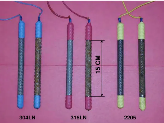
) exposed to the concrete. The corroding CS and rust-contaminated SS (originating from CS) samples were prepared by placing CS and SS bars alternately in a wet room with 95% ± 5% relative humidity and 22 oC ± 2 oC temperature for 10 days to allow the CS rust to accumulate on the CS and SS surfaces. Figure 2 shows three types of SS reinforcing bars with clean surfaces and rust contaminated surfaces. The concrete mixtures were cast into plexi glass molds, and after 24 hours the concrete specimens were de-molded and then cured for 28 days in the above mentioned wet room. The specimens were then relocated into an environmental chamber with 80% relative humidity and temperature cycling between 25oC and 45oC to accelerate the rebar
corrosion during the test period. The galvanic coupling current was measured between the two bars in the same specimen using a Keithley 485 Picoammeter.
3 Theoretical considerations
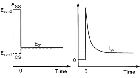
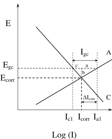
Galvanic corrosion occurs when two (or more) dissimilar metals (such as SS and CS) are electrically connected in the same electrolyte. The difference in potential between these two metals is the driving force for the galvanic corrosion cell. When connected, the potentials of two metals are forced to shift to a new intermediate value that usually lies closer to that of the more active metal. The metal that originally had a more negative potential (here corroding CS) is subjected to an oxidation process. The more noble metal (here SS), which originally had a more positive potential, is polarized to the more negative potential and subjected to a reduction process. As a result, the electrons transfer through the metals from the active metal (anode) to the noble one (cathode). The potentials and corresponding coupling current are shown in Figure 3. After an initial current spike to charge the double layer of the electrode, the current levels off to a stable value. This current density is the measured galvanic coupling current density, (Igc).
The Evans diagram for galvanic coupling of the active metal (here corroding CS) and the noble metal (here SS) that leads to the changes of potential and current on the corroding electrode is shown in Figure 4(assuming electrode surfaces had a 1:1 ratio and faced each other). It illustrates the relationship between the galvanic coupling current and the total corrosion current on the corroding CS. The anodic reaction on the corroding CS is:
Fe J Fe 2+ + 2e- (1)
O2 + 2 H2O + 4e-⇄ 4 OH - (2)
Prior to galvanic coupling, the corroding CS has its own corrosion potential (Ecorr) and
corresponding corrosion current (Icorr, current density at the intersection point of lines A and C).
Once the corroding CS is coupled with SS, the potential of corroding CS shifts positively from Ecorr to the galvanic coupling potential Egc. Correspondingly, the cathodic current at the
corroding CS decreases from Icorr to Ic1 and the anodic current of the corroding CS increases from
Icorr to Ia1. The current Ia1 is the new corrosion current density on the corroding CS after coupling
with SS. Therefore, the cathodic current density (Ic1) is lower than the anodic current density (Ia1)
on the corroding CS. The cathodic and anodic current densities (Ic2 and Ia2) on the coupled SS
compensate for this current difference. As a result, the sum of the anodic currents should remain equal to the sum of the cathodic currents in this coupling system, i.e.:
Ia1 + Ia2 = Ic1 + Ic2 (3)
The increase of corrosion current density (ΔIcorr) on the corroding CS is the difference between
Ia1 and Icorr and the measured galvanic coupling current density (Igc) is the difference between Ia1
and Ic1, as follows:
ΔIcorr = Ia1 - Icorr (4)
Igc = Ia1 – Ic1 (5)
Since Icorr is larger than Ic1, ΔIcorr must be smaller than the measured Igc. Based on the
experimental results obtained on the corroding CS, the Tafel slopes of anodic and cathodic reactions at the low overpotential region were 40 mV decade-1 and 60 mV decade-1, respectively
[16]. These values are in good agreement with the Tafel slope values obtained by Kabanov et al. [17]. From figure 4, the anodic slope can be written as:
40 = a b
(6)
and similarly the cathodic slope can be written as:
60 = c b
(7)
Dividing equation (6) by equation (7) yields:
60 40 = c b a b (8)
after rearranging, the following is obtained:
60 40 = a c (9)
This clearly shows that the measured Igc compensates partially (part c, about 40%) for the
decrease in the cathodic current and partially (part a, about 60%) for the increase in the corrosion current, ΔIcorr, on the corroding CS.
To calculate the percentage increase in the corrosion current density as a result of galvanic coupling, a comparison between ΔIcorr and Icorr is necessary. It is important to note that
ΔIcorr from the coupling between corroding CS and SS should be compared to that resulting from
the coupling between corroding CS and passive CS, since the latter situation always exists in concrete structures. If the galvanic current between corroding CS and SS is smaller than that between corroding and passive CS, then the use of SS, which is in electrical contact with CS in a concrete structure, will not increase the risk of corrosion in CS.
4 Results and discussion
4.1 Galvanic coupling current density
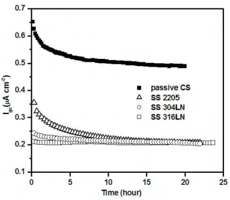
Figure 5 shows the galvanic coupling current densities, Igc, measured by connecting corroding
CS with passive CS or SS (2205, 304LN and 316LN). The current densities decrease gradually until they reach a stable value after the initial pulse, which was caused by the current charge for the double layer in the interface between the steel and the electrolyte. It is clearly shown that the galvanic coupling current density between the corroding CS and SS is less than half of that between corroding CS and passive CS. The corrosion rate of the corroding CS was determined by a linear polarization resistance technique and was found to be 13.3 ± 0.4 μA cm-2 at the
corrosion potential of –0.6 V vs SCE. The Igc values and percentage increase of Igc when
corroding CS was coupled with passive CS or several SS are listed in Table 1. As mentioned earlier ΔIcorr is about 60% of Igc. Therefore, the corrosion rate increase due to galvanic coupling
between corroding CS and passive CS is about 2.4%, while that due to galvanic coupling between corroding CS and SS is only about 1.0%. Since the galvanic coupling effect introduced by SS is about 1% and smaller than that of passive CS, galvanic coupling between SS and CS will not increase the risk of CS corrosion.
4.2 Effect of oxygen on cathodic reduction current
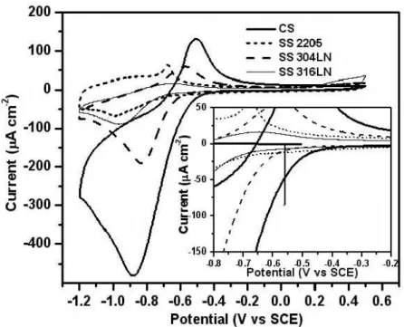
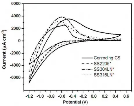
The oxygen reduction and oxidation reaction behaviours of passive CS and SS 2205, 304LN and 316LN were examined by a cyclic voltammetry technique and the results are shown in Figure 6.
The cathodic and anodic current densities on all SS were significantly smaller than those on passive CS. The corrosion potential of the corroding CS is about –0.55 V to –0.6 V. Therefore, the potential for galvanic coupling between corroding CS and passive CS or SS should be at this potential range. Furthermore, the reactions on passive CS or SS are cathodic reactions. From the inset of Figure 6, it can be clearly seen that the cathodic reduction current densities of all SS are much lower than those on the passive CS in this potential range. Obviously the SS surface is not favourable for this reduction reaction.
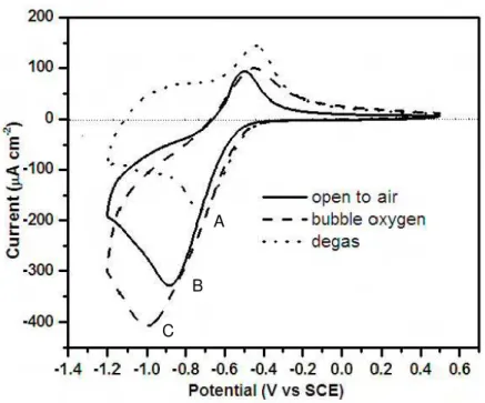
The effect of dissolved oxygen on the cathodic reduction current density of passive CS electrodes was examined in an electrochemical cell. First, a cyclic voltammogram was measured in the electrochemical cell while open to air. Oxygen was then bubbled into the cell to saturate the electrolyte solution before another cyclic voltammogram was measured. Afterwards, the solution in the cell was degassed by bubbling Argon into the cell to remove the dissolved oxygen. Subsequently, another cyclic voltammogram was measured, as shown in Figure 7. The cathodic current peak was dominated by the reaction of ferric to ferrous transformations [18] (FeOOH/Fe(OH)2). When oxygen was purged from the solution (i.e. the concentration of oxygen
in the solution was the lowest), the cathodic current had the smallest peak with a value of –180 μA cm-2 at –0.72 V (peak A). The areas between the zero line and curves of this cyclic voltammogram (representing the electric charges involved in the electrochemical reactions) for the cathodic and anodic scans are almost equal, indicating that reactions represent electrode surface reduction and oxidation are reversible. When the concentration of oxygen in the solution was increased (cell open to air), the cathodic current peak increased to a value of –330 μA cm-2
at –0.87 V (peak B). When the electrolyte solution was saturated with oxygen, the peak in cathodic current increased further to a value of –400 μA cm-2
charge for the cathodic reduction also increased and indeed, became much larger than that for anodic oxidation, indicating that there was a significant oxygen (dissolved in the solution) reduction reaction involved. In the cathodic scan of the potential region, between –0.4 V and –0.72 V, the effect of oxygen concentration on the cathodic reaction was not observed since the reduction of the oxidized metal surface was the dominant reaction. The slight increase in the reduction currents under oxygen and argon bubbling was probably caused by solution stirring that arose from bubbling the solution. In the anodic scan (from –1.2 V to –0.5 V), the current shift to more negative values when open to air and during oxygen bubbling is due to the process of continuing oxygen reduction. The increase in current in the more positive region (–0.5 V to +0.5 V) is again likely due to the bubbling action causing an increase in the diffusion process.
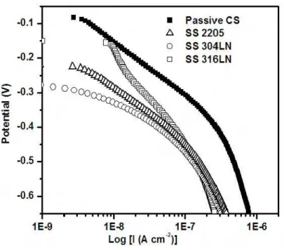
Figure 8 shows the cathodic polarization curves for passive CS and SS. The cathodic current densities on SS are all much smaller than those on passive CS in the region of –0.5 V to –0.6 V. As described above, Igc is limited by the cathodic reduction reaction (eq. 2) on the
passive CS or SS when the corroding CS is coupled to either of them. Therefore Igc induced by
SS is much smaller than that induced by passive CS when these metals are coupled with corroding CS.
4.3 Effect of rust contamination
When a SS surface is contaminated by corrosion products from corroded CS, its electrochemical characteristics are altered. These corrosion products will obviously affect the galvanic coupling behavior of SS since they have a significant effect on the cathodic reaction of SS. The cyclic voltammograms of SS 2205, 304LN and 316LN with rust adhered on the surface are shown in
Figure 9. It was found that the profiles on these SS are very similar and are totally different from the cyclic voltammograms obtained on SS with rust-free surfaces , as shown in Figure 6. In particular, the clear cathodic reduction peaks have all disappeared on the rust-contaminated SS. Also, the cathodic and anodic currents are all much higher (> 2000 μA cm-2
) than those on rust-free SS (< 200 μA cm-2
). Compared to the cyclic voltammogram of the corroding CS (solid line in Figure 9) the profiles are very similar. Clearly, the surfaces of these CS and SS samples are all covered by corrosion products; they have similar exterior surface conditions with the only difference being that on the corroding CS surface, the rust is electrochemically formed, while on the SS surface, it adheres physically. However, the latter has a much larger surface area than the rust-free SS surface. For the oxygen reduction reaction, O2 needs to diffuse to the metal surface,
then adsorb onto metal or metal oxide sites before being further reduced to OH-. Since the
surface area of rust-contaminated SS has increased considerably, so do the oxidation and reduction currents.
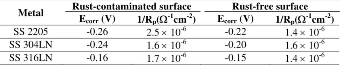
The corrosion potential and polarization resistance obtained from linear polarization experiments on SS 2205, 304LN and 316LN with and without rust present are listed in Table 2. It was found that Ecorr and 1/Rp (proportional to the corrosion rate) in both cases were similar and
remained almost unchanged, even for the SS surfaces covered by rust. This is because anodic dissolution of metal is the rate-determining step at the Ecorr of SS when it is not coupled with the
CS. The layer of rust cover on the surface of SS might affect the cathodic reduction rate but does not alter the structure of the passive film or the rate of SS metal dissolution. Therefore, both the corrosion potential and current remained nearly unchanged.
The cathodic polarization curves of SS with and without rust present are shown in Figure 10. It was found that cathodic current densities are all much larger for the rust-contaminated SS
than for those of rust-free SS. This agrees with the results of cyclic voltammograms. The increase of cathodic current can be attributed to an increase in the actual surface area created by the adhered rust on the SS surface. The rust-contaminated SS behaves as a cathode when coupled with corroding CS. As a result the galvanic coupling current density for corroding CS coupled with rust contaminated SS can be significantly higher than that with rust-free SS. The Igc curves
obtained from coupling corroding CS with SS 2205, 304LN and 316LN in the presence and absence of rust are shown in Figure 11. It is evident that the values of Igc were much higher on all
rust-contaminated SS than that with rust-free SS. It took a much longer time for Igc to reach
relatively stable values on rust-contaminated SS, likely due to the uneven activity and non-uniformity of the adhered rust on the surface of the SS electrodes.
4.4 Corroding CS bar coupled with passive CS or SS bars in concrete
The galvanic coupling test was also performed between two steel bars embedded in the same concrete specimen. Figure 12 shows the galvanic coupling potential and Igc of corroding CS
coupled with SS (no rust cover). CS rebars were cast in half of the concrete specimen containing 1.5% chloride ions, while SS rebars were embedded in the other half of the concrete specimen containing 3.5% chloride ions. Before coupling the two rebars, the open circuit potential of CS was more negative than that of SS (as indicated by the potentials before time 0). After the connection of the two rebars, the potentials of two metals shifted to a common value and varied between –0.12 V and –0.3 V over 220 days. In this period of time, the galvanic coupling current densities were relatively low (about a few nA cm-2), indicating no considerable galvanic coupling
an initial corrosion development stage. After the 220th day, the high temperature of the
environmental chamber was changed from 45oC to 50oC. As a result, the coupling potential
shifted towards more negative values at about –0.25 V to –0.45 V, while the Igc increased
significantly to around 80 nA cm-2, 120 nA cm-2 and 226 nA cm-2 for SS 2205, 304LN and
316LN, respectively. Igc then decreased gradually to very low values (approaching 0) for all three
SS due to increased contact resistance between CS and the concrete that arose from severe cracking of the concrete near the corroding CS rebars.
The galvanic coupling potential and Igc measured from corroding CS coupled with the
passive CS is shown in Figure 13. Two CS bars were embedded in the concrete specimens, one in chloride-free concrete and the other in concrete containing 1.5% chloride ions. During the first 220 days, the coupling potential varied around –0.15 V and the coupling current remained very low (< 20 nA cm-2
). After 275 days, the coupling potential dropped to –0.4 V, while the coupling current increased rapidly to 850 nA cm-2, then decreased to a very low value, close to 0 nA cm-2,
due to concrete cracking around the active rebars. It was therefore shown that Igc between active
and passive CS was much higher than that between active CS and SS, even when the SS was in concrete containing 3.5% chloride ions. This result is in good agreement with that obtained in the saturated Ca(OH)2 solution in the electrochemical cell. This demonstrates that when SS
reinforcing bars are coupled with corroding CS bars, Igc is much smaller (less than 226 nA cm-2)
than that observed when passive and active CS rebars are coupled (about 850 nA cm-2).
Therefore, replacing CS reinforcement with SS would not increase the risk of corrosion to the CS reinforcement.
It was also found that, unlike the measurement in the electrochemical cell, the galvanic coupling current in the concrete did not reach its stable value shortly after coupling. The current
remained very low over more than 200 days before finally increasing. This was due to the fact that the CS used as an active electrode in the electrochemical cell was substantially corroded before the experiment and its corrosion potential was stable at around –0.55 V to –0.60 V. When this electrode was coupled with passive CS or SS, the observed galvanic coupling behavior was determined by the cathodic reduction reaction on passive CS or SS. However CS used in concrete specimens was corrosion free before it was cast in the concrete specimens. During the first 200 days, the corrosion gradually developed on the CS when exposed to 1.5% chloride ions in concrete under environmental conditions of temperature cycling and high humidity.
Figure 14 shows photos of the concrete specimens in which the active CS (in concrete containing 1.5% chloride ions) was coupled with different types of SS (in concrete containing 3.5% chloride ions) or with passive CS (in chloride-free concrete). The photos were taken at the end of the two-year test period. It can be seen that all concrete with SS embedded were in good condition; corrosion rate of 0.01 μA cm-2
measured on these SS and visual inspection of these SS by opening concrete specimens confirmed that all these SS were in very good condition, indicating that the SS was in a passive state. However all concrete specimens with CS embedded in concrete containing 1.5% chloride ions were severely cracked (as shown in the photos), demonstrating that the CS had been subjected to severe active corrosion. This cracking is a direct consequence of the severe CS reinforcement corrosion that occurs in the presence of 1.5% chloride ions.
4.5 Corroding CS coupled with rust contaminated SS in concrete
Corroding CS coupled with rust contaminated SS was tested in concrete specimens. Figure 15 shows the galvanic coupling potential and Igc of corroding CS coupled with rust-covered SS. The
CS was embedded into the region of the concrete specimen containing 1.5% chloride ions, while rust-contaminated SS was cast into the region of the concrete specimen containing 3.5% chloride ions. The coupling potentials varied around –200 mV vs SCE while Igc increased and decreased
several times. After coupling for 220 days, the coupling potential shifted to more negative values. Igc increased to 1.3 μA cm-2. This value was several folds higher than that for rust-free SS
rebars (0.23 μA cm-2
as shown in Figure 12). This result is again in agreement with that obtained in the saturated Ca(OH)2 solution in the electrochemical cell. As described in the previous
section, this Igc increase is due to the increased surface area on the SS rebars that arises from rust
products and leads to an increase of the cathodic reduction current. This cathodic current increase depends on the thickness and coverage of the adhered rust. As a result, the galvanic coupling current density for corroding CS coupled with rust contaminated SS can be significantly higher than that with rust-free SS. Therefore, it is very important that all SS rebars be protected from contamination by CS during the processes of transportation, storage and installation to reduce the risk of corrosion of coupled CS rebars.
5 Conclusions
• The galvanic coupling of SS and CS in saturated Ca(OH)2 solutions will not increase the
fact, the slight increase in corrosion rate of CS due to galvanic coupling of SS and corroded CS was less than for the combination of non-corroded CS and corroded CS. SS, with its ability to resist chloride-induced corrosion, can be used in areas vulnerable to chloride contamination.
• The rate determining step of the galvanic coupling process is a cathodic reduction reaction on passive CS or SS when either of these metals are coupled with a corroding CS in a saturated Ca(OH)2 solution. The cathodic reduction current on SS is significantly lower than passive
CS, leading to a much lower Igc induced by SS than passive CS.
• The galvanic coupling tests between passive CS and SS show that Igc was about 1 nA cm-2
for all three types of SS, well below the long-term maintenance-free current density for CS, even when these SS were in the 3% chloride ion solution. Therefore, galvanic coupling of passive CS and SS will not initiate corrosion on passive CS.
• From the tests performed in the electrochemical cell and concrete specimens, it was found that the presence of rust on SS that originated from corroding CS, could result in increased corrosion rates on the coupled corroding CS. It is strongly recommended that SS rebars should be handled separately during transportation, field storage and construction to avoid contamination from CS corrosion products.
• The galvanic coupling tests carried out in concrete specimens confirmed the laboratory experimental results. When SS reinforcing bars were coupled with corroding CS bars, Igc was
much lower than in the coupling between passive and corroding CS reinforcements. Therefore, the judicious use of SS in high corrosion risk areas of concrete structures can be considered a cost-effective option for preventing corrosion and thus extending the service life of concrete structures.
6 Acknowledgments
The authors gratefully acknowledge the contributions and support of The Nickel Institute (previously the Nickel Development Institute), Alberta Transportation, The City of Ottawa, The Ministry of Transportation of Quebec and Valbruna Canada Ltd. Thanks are also due to Bruce Baldock, Glendon Pye, Gordon Chan and Bob Myers of NRC-IRC for their help with the experimental work.
References
1. Nurnberger U, editor (1996) Stainless steel in concrete, European Federation of Corrosion Publications, Vol. 18, London: Institute of Materials.
2. Knudsen A, Jensen F, Klinghoffer O, Skovsgaard T (1998) International Conference on Corrosion and Rehabilitation of Reinforced Concrete Structures, Orlando, Florida, p. 15. 3. Knudsen A, Skovsgaard T (2001) Concrete Engineering, , 5(3), p. 59.
4. Klinghoffer O, Frolund T, Kofoed B, Knudsen A, Jensen F, Skovsgaard T (2000) Corrosion of reinforcement in concrete: corrosion mechanisms and corrosion protection Ed. J. Mietz, R. Polder, and B. Elsener, London, pp. 121-133.
5. Cochrane D (1999) Infrastructure Regeneration and Rehabilitation Improving the Quality of Life Through Better Construction: A Vision for the Next Millennium, Ed. Swamy R,
Sheffield Academic Press, Sheffield, pp. 497-506.
6. Pérez-Quiroz J, Terán J, Herrera M, Martínez M, Genescá J (2008) Journal of Constructional Steel Research, 64, pp 1317-1324.
7. Abreu C, Cristóbal M, Montemor M, Nóvoa X, Pena G, Pérez M (2002) Electrochimica Acta, 47, pp 2271-2279.
8. Bertolini L, Gastaldi M, Pastore T, Pedeferri M, Pedeferri P (1998) International Conference on Corrosion and Rehabilitation of Reinforced Concrete Structures, Orlando, Florida, p. 13. 9. Bertolini L, Gastaldi M, Pastore T, Pedeferri M (1999) Vol. 3; Properties and Performances
Stainless Steel: Science and Market- European Congress; 3rd; pp. 131-140, Associazione
Italiana di Metallugia, Chia Laguna, Italy.
10. Bertolini L, Elsener B, Pedeferri P, Poder R (2004) Corrosion of steel in Concrete: Prevention, Diagnosis, Repair, Wiley-VCH.
11. Bertolini L, Pedeferri P (2002) Corrosion Review, 20, p. 129.
12. Qian S, Qu D, Coates G (2006) Canadian Metallurgical quaterly, Vol 45, No. 4, pp 475-484. 13. Hope B (2001) Final report of MTO special project Q900076, ISBN 0-7794-0479-3, MI-181,
Feb.
14. Webster H (1997) COR-97-7810-N, CORRENG Consulting Service Inc., Downsview, Ontario.
15. Seibert P (1998) M.Sc Thesis, Queen's University.
16. Bockris J, Khan S (1993) Surface Electrochemistry: a molecular level approach, Plenum press, New York, p. 767.
17. Kabanov B, Burshtein R, Frumkin A (1947) Discuss. Faraday Soc. 1, p259. 18. Vukovic M (1994) Corrosion Science, 37, p. 111.
Table 1. Relationship between Igc and Icorr for various metals
coupled to corroding CS at –0.6 V vs SCE
Steels Igc (μA cm-2) Igc/Icorr (%) ΔIcorr/Icorr (%)
Passive CS 0.53 4.0 2.4
SS 2205 0.22 1.7 1.0
SS 304LN 0.23 1.7 1.0
SS 316LN 0.24 1.8 1.1
Table 2. Values of Ecorr and 1/Rp of SS with and without rust on surface
Metal Rust-contaminated surface Rust-free surface
Ecorr (V) 1/Rp(Ω-1cm-2) Ecorr (V) 1/Rp(Ω-1cm-2)
SS 2205 -0.26 2.5 × 10⁻⁶ -0.22 1.4 × 10⁻⁶
SS 304LN -0.24 1.6 × 10⁻⁶ -0.20 1.6 × 10⁻⁶
15 CM
304LN 316LN 2205
Fig. 2 Photo of SS 304LN, 316LN and 2205 rebars with and without rust cover prepared for embedding in concrete specimens.
Fig. 4 Changes of potentials and current densities on corroding CS after being coupled with SS.
E
corrI
corrE
gcI
a1I
c1Log (I)
E
A
C
I
gc a c bI
corΔ
rFig 5 Galvanic coupling current densities, Igc, obtained by coupling CS with passive CS
Fig. 6 Cyclic voltammograms of passive CS and SS measured in saturated Ca(OH)2 solution (Inset shows enlarged current scale).
A
B
C
Fig. 8 Cathodic polarization curves of passive CS and SS measured in saturated Ca(OH)2 solution.
Fig. 9 Cyclic voltammograms of corroding CS and SS* (with rust adhesion) measured in saturated Ca(OH)2 solution.
Fig. 10 Cathodic polarization curves of SS with and without rust adhesion measured in saturated Ca(OH)2 solution (* with rust adhesion).
Fig. 11 Curves of Igc obtained by coupling corroding CS with SS with and without
Fig. 12 Galvanic coupling potentials and current densities of corroding CS (in concrete with 1.5% Cl-) coupled with SS (in concrete with 3.5% Cl-).
Fig. 13 Galvanic coupling potentials and Igc of active CS (in concrete with 1.5% Cl-)
Corroding CS (1.5% Cl-) coupled with passive CS (0% Cl-)
Corroding CS (1.5% Cl-) coupled with SS (3.5% Cl-)
Fig. 14 Photos of concrete specimens in which the corroding CS (in concrete containing 1.5% Cl-) was coupled with passive CS (in concrete with 0% Cl-) or SS (in concrete containing
Fig. 15 Galvanic coupling potential and Igc of active CS (in concrete containing 1.5% Cl-)