https://doi.org/10.4224/23000736
READ THESE TERMS AND CONDITIONS CAREFULLY BEFORE USING THIS WEBSITE. https://nrc-publications.canada.ca/eng/copyright
Vous avez des questions? Nous pouvons vous aider. Pour communiquer directement avec un auteur, consultez la première page de la revue dans laquelle son article a été publié afin de trouver ses coordonnées. Si vous n’arrivez pas à les repérer, communiquez avec nous à [email protected].
Questions? Contact the NRC Publications Archive team at
[email protected]. If you wish to email the authors directly, please see the first page of the publication for their contact information.
Archives des publications du CNRC
For the publisher’s version, please access the DOI link below./ Pour consulter la version de l’éditeur, utilisez le lien DOI ci-dessous.
Access and use of this website and the material on it are subject to the Terms and Conditions set forth at
Camera-based indirect vision systems for heavy duty vehicles: phase I
Mcwha, T.; Desouza, F.
https://publications-cnrc.canada.ca/fra/droits
L’accès à ce site Web et l’utilisation de son contenu sont assujettis aux conditions présentées dans le site LISEZ CES CONDITIONS ATTENTIVEMENT AVANT D’UTILISER CE SITE WEB.
NRC Publications Record / Notice d'Archives des publications de CNRC:
https://nrc-publications.canada.ca/eng/view/object/?id=3fb13edf-2901-4ed1-b5ce-2cf9ce0b0817 https://publications-cnrc.canada.ca/fra/voir/objet/?id=3fb13edf-2901-4ed1-b5ce-2cf9ce0b0817
Council Canada de Recherches Canada
Automotive and
Surface Transportation
Automobile et transports de surface
Camera-Based Indirect Vision Systems
for Heavy Duty Vehicles – Phase I
Prepared for:
ecoTECHNOLOGY for Vehicles
Stewardship and Sustainable Transportation Programs Transport Canada 330 Sparks St. Ottawa, ON K1A 0N5 Canada Prepared by: T. McWha, P.Eng. F. Desouza, Ph.D. Project A1-001055 ST-GV-TR-0001 August 8, 2013 UNLIMITED UNCLASSIFIED
Copyright 2013. This document contains confidential information that is proprietary to NRC Automotive and Surface Transportation. No part of its contents may be used, copied, disclosed or conveyed to any party in any manner, in whole or in part, whatsoever without prior written permission from NRC Automotive and Surface Transportation.
August 8, 2013 National Research Council Canada Automotive and Surface Transportation
Revision B
CAMERA-BASED INDIRECT VISION SYSTEMS FOR HEAVY DUTY VEHICLES – PHASE I
Prepared for:
ecoTECHNOLOGY for Vehicles
Stewardship and Sustainable Transportation Programs Transport Canada
330 Sparks St. Ottawa, ON K1A 0N5 Canada
National Research Council Canada Automotive and Surface Transportation 2320 Lester Rd.
Ottawa, ON K1V 1S2 Canada
Technical Report ST-GV-TR-0001
Copyright 2013. This document contains confidential information that is proprietary to NRC Automotive and Surface Transportation. No part of its contents may be used, copied, disclosed or conveyed to any party in any manner, in whole or in part, whatsoever without prior written permission from NRC Automotive and Surface Transportation.
August 8, 2013 National Research Council Canada Automotive and Surface Transportation
Revision B
C
HANGE
C
ONTROL
Revision Date Description Author
A March 28, 2013 Initial release T. McWha
August 8, 2013 National Research Council Canada Automotive and Surface Transportation
Revision B
D
ISCLAIMER
This report reflects the views of the authors only and does not reflect the views or policies of Transport Canada.
Neither Transport Canada, nor its employees, makes any warranty, express or implied, or assumes any legal liability or responsibility for the accuracy or completeness of any information contained in this report, or process described herein, and assumes no responsibility for
anyone's use of the information. Transport Canada is not responsible for errors or omissions in this report and makes no representations as to the accuracy or completeness of the information. Transport Canada does not endorse products or companies. Reference in this report to any specific commercial products, process, or service by trade name, trademark, manufacturer, or otherwise, does not constitute or imply its endorsement, recommendation, or favoring by Transport Canada and shall not be used for advertising or service endorsement purposes. Trade or company names appear in this report only because they are essential to the objectives of the report.
References and hyperlinks to external web sites do not constitute endorsement by Transport Canada of the linked web sites, or the information, products or services contained therein. Transport Canada does not exercise any editorial control over the information you may find at these locations.
August 8, 2013 National Research Council Canada Automotive and Surface Transportation
Revision B
A
BSTRACT
Indirect vision systems are used by drivers to identify objects that do not fall directly within their line of sight. This can be accomplished through the use of a conventional mirror-based indirect vision system or by a camera-based indirect vision system. The purpose of this study is to evaluate the design factors surrounding the use of camera-based indirect vision systems, quantify the possible fuel savings which may be achieved through the use of such systems and to identify and quantify any secondary effects related to their use.
The design factors were separated into human design considerations and equipment design considerations. The two categories of design factors were evaluated through a literature review of past similar studies as well as other pertinent journal articles and texts.
The possible fuel savings which may be realized through the use of a camera-based indirect vision system were quantified by performing full-scale component testing in a 2 m by 3 m wind tunnel. The results of the component testing were compared to previously performed full-scale vehicle testing in order to determine the overall reduction in the vehicle drag coefficient
expected through the use of a camera-based indirect vision system and, in turn, the possible fuel savings.
August 8, 2013 National Research Council Canada Automotive and Surface Transportation
Revision B
E
XECUTIVE
S
UMMARY
Indirect vision systems are used by drivers to identify objects that do not fall directly within their line of sight. This can be accomplished through the use of a conventional mirror-based indirect vision system or by a camera-based indirect vision system. The presence of mirror-based indirect vision systems on highway tractors is a significant source of aerodynamic drag. The replacement of such systems in favour of camera-based indirect vision systems can reduce the overall drag coefficient of the vehicle, and in turn reduce fuel consumption.
The purpose of this study is to evaluate the design factors surrounding the use of camera-based indirect vision systems, quantify the possible fuel savings which may be achieved through the removal of conventional mirrors and to identify and quantify any secondary effects related to their use.
The study consists of two phases. Phase I involves a literature review concerning the current state of technology and the human factors associated with the use of a camera-based indirect vision system. Phase I also involves the design and installation of a prototype system on a subject vehicle. Phase II, not described within this report, will consist of field testing of the prototype system designed in Phase I. The field testing will consist of both closed course and highway use of the prototype system by drivers with a range of age and experience.
The realization of the possible fuel savings and the associated reduction in greenhouse gas emissions has led to research into the development of camera-based indirect vision systems to replace conventional mirror systems. Several previous studies have evaluated the design requirements of camera-based indirect vision systems. Additional studies have evaluated the use of camera systems on city buses with the aim of reducing blind spots to minimize the number of side crash events. To date, the majority of research has been focused on the development of driver vision enhancement systems rather than the use of camera systems to replace mirrors.
A camera-based indirect vision system consists mainly of cameras and monitors. Video data captured by the cameras will be displayed on monitors located within the vehicle. It is therefore important to understand how the eye is used to gather visual information when designing a camera-based indirect vision system for use on heavy duty vehicles to ensure that the system does not put undue stress on the eye or distract from other visible sensory information required to operate the vehicle in an efficient manner. Visual acuity, temporal acuity, the visual field, accommodation, presbyopia, brightness, contrast, ciliary muscle fatigue, depth perception, information processing and colour blindness must all be considered when designing a camera-based indirect vision system.
In addition to the human factors design considerations, there are numerous equipment factors which must be investigated and evaluated in order to design a camera-based indirect vision system. The camera fields of view, camera location, image resolution, monitor location, monitor size, image reversal, infrared capabilities, screen brightness, the use of colour, power
consumption, system mass, environmental concerns, vibrations, redundant systems, polarization of light, vehicle width, wide loads, and the limitations of present-day camera technology must all be taken into consideration when designing such a system.
The use of a camera-based indirect vision system will allow for processing of the captured video data to extract meaningful information that may assist drivers to operate their vehicle in a more efficient manner. However, when considering how the visual data may be processed, one must keep in mind that data processing takes time which will induce a certain amount of lag in the system, which is undesirable. The camera-based indirect vision system may be used to identify
August 8, 2013 National Research Council Canada Automotive and Surface Transportation
Revision B
targets, monitor the angle of the trailer, assist in staying in one’s lane as well as use infrared light to detect targets in complete darkness.
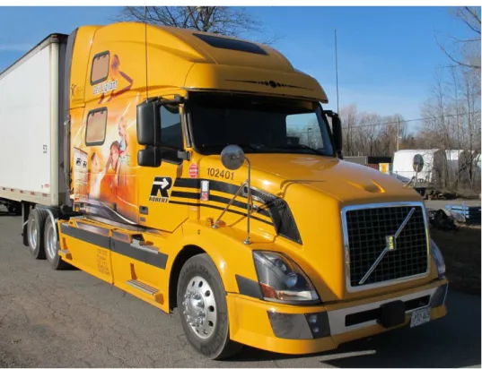
The basic design goal for the camera-based indirect vision system was that the same visual information available through the use of a conventional mirror-based indirect vision system was available through the use of the camera-based system. The subject vehicle on which the
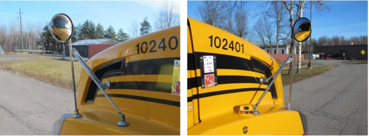
camera-based indirect vision system was installed was a Volvo VN780. The subject vehicle had two west coast mirrors on either side of the vehicle, two fender-mounted convex mirrors and a look-down mirror on the passenger side. All four of the mirrors were replaced by cameras and monitors in an attempt to replicate the available field of view.
In order to determine the required field of view of the camera-based indirect vision system, the fields of view of the conventional mirror-based system were quantified. This was accomplished by connecting a 53 foot trailer to the subject vehicle, and having a driver of average height sit in the driver seat of the subject vehicle, adjust his mirrors as he would for normal driving and describe his field of view to the test engineer. In addition to the indirect visibility measurements, measurements of the direct visibility of the driver were also taken. These were used later to compare the visual obstruction of the mirrors to the visual obstruction of the monitors. Interior vehicle measurements allowed for the calculation of the maximum required system resolution, taking into account normal visual acuity as well as the distance between the vehicle operator’s eyes and the A-pillars.
Several different cameras from various manufacturers were reviewed based on the
manufacturer’s specifications. Both standard definition (SD) analog and high definition (HD) digital cameras were considered for use in the system. However, the majority of the HD
cameras surveyed required data compression to transmit the captured video. The compression of the data takes time, inducing noticeable lag between the time the image was captured and the time the image was displayed on the monitor. Lag in a camera-based indirect vision system is undesirable, therefore HD cameras were deemed inappropriate for use in the prototype system. The camera selected for the prototype camera-based indirect vision system was a Panasonic WV-CP624 which has a good combination of image resolution and day and nighttime viewing characteristics. The selected lens for the camera was a Panasonic PLZ5-50DN with a variable field of view from 5° to 50°. The variable field of view capabilities of the lens allowed for the use of a single camera and lens solution for all four cameras.
Several different monitors from various manufacturers were reviewed based on the
specifications provided on their data sheets. The monitors selected for use in the prototype camera-based indirect vision system are manufactured by ToteVision. Three different sizes were selected for the four monitors: 142 mm (5.6 in), 163 mm (6.4 in) and 213 mm (8.4 in). It was important to determine the overall change in aerodynamic drag coefficients through the use of a camera-based indirect vision system to determine the change in vehicle fuel
consumption that could be realized through the use of such systems. In order to perform the aerodynamic testing, two separate camera fairings were designed. One of the camera fairings was designed to be placed in the front fender location. The other camera fairing was designed to be mounted in the location where the mirrors are conventionally placed as there are a few camera-based indirect vision systems under development which have the cameras placed in such a location. It was deemed important to test a similar fairing in order to determine the possible fuels savings through the use of such a camera location.
It was determined that the optimal location for the cameras was on the front fender of the
subject vehicle. There are two cameras mounted on either side of the vehicle, one on top of the other. The camera in the uppermost position was used as the convex mirror surrogate camera. The camera in the lowermost position was used as the flat mirror surrogate camera.
August 8, 2013 National Research Council Canada Automotive and Surface Transportation
Revision B
It was determined that the ideal locations for the monitors are on the left and right A-pillars. The monitors mounted on the left A-pillar were a ToteVision LCD-562 mounted above a ToteVision LCD-642. The monitors mounted on the right A-pillar were a ToteVision LCD-642 mounted above a ToteVision LCD-842HD.
Since the camera-based indirect vision system was replicating a mirror-based system, it was necessary to mirror the images captured by the cameras. A Colorado Video NVVN420CS mirror box was used to perform the mirroring operation.
In addition to the cameras and monitors, an IR illuminator was mounted to the side of the subject vehicle to provide additional IR lighting during nighttime driving conditions. The selection of the IR mode on the cameras as well as the powering of the IR illuminator for the prototype system was performed via a toggle switch accessible by the driver of the vehicle. The camera system field of view was configured using the variable field of view lenses to replicate the field of view provided by the mirror-based system. The camera system field of view for the flat mirror surrogates is slightly larger than that provided by the flat mirrors themselves to account for driver head movements.
The visual obstruction of the mirror-based indirect vision system was compared to those of the camera-based system. The visual obstruction angles of the mirror-based system include both the west coast mirrors, the fender mounted convex mirrors and the A-pillars. The visual
obstruction angles of the camera-based system only include the visual obstruction of the largest monitor located on the A-pillar. The total visual obstruction angles were less for the camera-based indirect vision system than for the mirror-camera-based indirect vision system.
The power consumption of the prototype camera-based indirect vision system was used to calculate the approximate fuel required to power the system. Based on a system power consumption of 94.0 W and some assumptions concerning vehicle efficiencies and duration of system use per year, the prototype camera-based indirect vision system was expected to consume roughly 87.2 L of fuel each year.
An electrically powered, electronic camera-based indirect vision system may be subject to failure at a higher rate than a conventional mirror-based system. Assuming the vehicle operates for roughly 2500 hours per year, the system mean time to failure was calculated to be about 5.4 years.
The mass of the system will have an impact on the fuel consumption of the vehicle. Overall, there is a net decrease in mass of 5.26 kg when using the prototype camera-based indirect vision system instead of the mirror-based system. Based upon the overall mass decrease of the vehicle, the yearly estimated fuel savings due to a decrease in overall vehicle mass is roughly 1.8 L per year.
The cost of the prototype camera-based indirect vision system was approximately $8,980. Comparing this to the replacement cost of the mirror-based indirect vision system of
approximately $2,316, the camera-based indirect vision system costs approximately $6,664 more than a mirror-based system. However, the prototype system was purchased on a component basis and it was assumed that a production level system would cost significantly less.
In order to quantify the fuel savings which could be realized through the use of a camera-based indirect vision system it was important to quantify the gains in aerodynamic efficiency as a result of using such a system. To do so, full-scale testing of the camera-based indirect vision system components were tested in NRC-IAR’s 2 m by 3 m wind tunnel. Because wind tunnel testing was performed on a full-scale component basis only, the mirrors of the subject vehicle also had
August 8, 2013 National Research Council Canada Automotive and Surface Transportation
Revision B
to be tested. The testing of the mirrors allowed for the comparison of data from previous full-scale vehicle testing.
The results of the aerodynamic testing revealed a possible fuel savings of roughly 1,902 L per year.
Canadian Motor Vehicle Safety Standards (CMVSS) only requires a unit magnification mirror with 325 cm2 of reflective area on both sides of the vehicle. However, the subject vehicle had total of 1,107 cm2 of reflective area on each side of the vehicle due to the west coast mirrors, or roughly 340% the required amount. By assuming the smaller CMVSS minimums mirror has the same general shape as the tested mirror, and scaling the aerodynamic testing data, it is
estimated that a yearly fuel savings of about 1,896 L could be realized by using only the two small unit magnification mirrors as required by CMVSS instead of the stock mirrors.
By combining the change in fuel consumption associated with the power draw of the system, the change in vehicle mass and the change in aerodynamic efficiencies, the use of a camera-based indirect vision system is expected to save roughly 1,817 L of fuel per year. Using an estimated fuel price of $1.20 per liter, the estimated payback period for the use of the prototype camera-based indirect vision system is approximately 4.1 years. This payback period is camera-based upon the prototype system only and may be different for mass production level systems.
By multiplying the estimated fuel savings of 1,817 L by a factor of 2.69 kg of CO2 released per
liter of diesel fuel burned, the use of the prototype camera-based indirect vision system has the capability of reducing CO2 emissions by roughly 4,888 kg per year per vehicle. If camera-based
indirect vision systems were to be installed on all of the highway tractors operating on Canadian highways, it is estimated that the yearly reduction in CO2 emissions would be roughly 1,109,600
tonnes.
It is necessary that extensive testing be performed on the use of camera-based indirect vision systems to determine all of the human factors issues which may arise through the use of such systems. Although this report attempted to address all human factors issues, it is very likely that additional issues will arise during field testing. It will be important to perform both closed course and highway testing of the prototype camera-based indirect vision system. Drivers selected for the testing should be of various age and gender and have varying levels of experience. Ideally, a large number of drivers should be used during the testing phase. For highway testing, it will be important that the mirror-based indirect vision system be removed from the vehicle while testing the camera-based indirect vision system. This will require permits to operate on Ontario highways without mirrors as required by CMVSS 111. Thorough testing of the system is
required as it is of utmost importance that the use of camera-based indirect vision systems as a replacement for conventional mirror-based systems does not result in a degradation in the driver’s ability to operate their vehicle effectively.
August 8, 2013 National Research Council Canada Automotive and Surface Transportation
Revision B
T
ABLE OF
C
ONTENTS
1 Introduction ... 1 1.1 Purpose ... 1 1.2 Background ... 1 1.3 Scope ... 1 2 Literature Review ... 2 2.1 Previous Research ... 2
2.2 Existing Camera Systems ... 4
2.2.1 Commercially Available Aftermarket Systems ... 4
2.2.2 OEM Prototype Systems ... 4
3 Design Consideration ... 5
3.1 Human factors ... 5
3.1.1 Vision ... 5
3.1.2 Basic Structure of the Eye ... 5
3.1.3 Visual Acuity ... 6
3.1.4 Temporal Acuity ... 6
3.1.5 Visual Field ... 7
3.1.6 Accommodation and Presbyopia ... 7
3.1.7 Brightness ... 8
3.1.8 Contrast ... 9
3.1.9 Ciliary Muscle Fatigue ... 9
3.1.10 Depth Perception ... 10
3.1.11 Information Processing ... 12
3.1.12 Colour Blindness ... 12
3.2 Equipment Factors ... 13
3.2.1 Camera Fields of View ... 13
3.2.2 Camera Location ... 13 3.2.3 Image Resolution ... 16 3.2.4 Monitor Location ... 17 3.2.5 Monitor Size ... 18 3.2.6 Image Reversal ... 19 3.2.7 Infrared Capabilities ... 19 3.2.8 Brightness ... 20
August 8, 2013 National Research Council Canada Automotive and Surface Transportation
Revision B 3.2.9 Use of Colour ... 20 3.2.10 Power Consumption ... 20 3.2.11 Mass ... 22 3.2.12 Environment ... 23 3.2.13 Vibrations ... 23 3.2.14 Redundant Systems ... 23 3.2.15 Polarization ... 24 3.2.16 Vehicle Width ... 24 3.2.17 Wide Loads ... 24 3.2.18 Camera Limitations ... 24
4 Augmented Sensing Capabilities ... 26
4.1 Target Identification ... 26
4.2 Trailer Angle Monitoring ... 26
4.3 Lane-Keeping Assist ... 27
4.4 Heat Sensing Capabilities ... 27
5 Prototype System ... 28
5.1 Design Goals ... 28
5.2 Subject Vehicle... 28
5.3 Vehicle Measurements ... 31
5.4 Optimal System Resolution ... 33
5.5 Camera Selection ... 33 5.6 Monitor Selection ... 34 5.7 Camera Fairings ... 36 5.8 Camera Location ... 38 5.9 Monitor Location ... 38 5.10 Mirror Box ... 40 5.11 IR Illuminator ... 41 5.12 IR selector ... 42
5.13 Camera System Field of View ... 43
5.14 Field of View Comparison ... 44
5.15 Power Consumption ... 46
5.16 Mean Time To Failure ... 48
5.17 System Mass ... 51
5.18 Cost ... 53
August 8, 2013 National Research Council Canada Automotive and Surface Transportation
Revision B
6.1 Description of Testing ... 54
6.2 Results ... 57
6.3 Aerodynamic Drag Associated with Mirrors Meeting CMVSS 111 Minimums ... 61
6.4 Comparison With Previous Testing ... 62
7 Summary of Results ... 63 7.1 Fuel Savings... 63 7.2 Payback Period ... 63 7.3 Reduction in CO2 Emissions ... 64 8 Future Work ... 65 8.1 Overview ... 65 8.2 Number of Drivers ... 65 8.3 Driver Experience ... 65 8.4 Driver Age ... 65 8.5 Driver Gender ... 65 8.6 Environmental Conditions ... 65
8.7 Closed Course Testing ... 66
8.8 Road Testing ... 66
9 Discussion ... 67
9.1 Travel Distance and Speed Used in Calculations ... 67
9.2 Mean Times to Failure ... 67
9.3 System Cost ... 67
9.4 Implications on Cost Savings Due to Increased Driver Awareness ... 67
9.5 Implementation of Camera-Based Systems ... 68
10 Conclusions ... 69
11 Recommendations ... 70
12 Acronyms and Abbreviations ... 71
13 References ... 73
August 8, 2013 National Research Council Canada Automotive and Surface Transportation
Revision B
L
IST OF
F
IGURES
Figure 1: Schematic view of the eye (from [20]) ... 5
Figure 2: Viewing an object through a mirror (from [7]) ... 14
Figure 3: Theoretically optimal location of unit magnification mirror surrogate camera (from [7]) ... 15
Figure 4: Optimal location of unit magnification mirror surrogate camera (from [7]) ... 15
Figure 5: Selected location of unit magnification mirror surrogate camera ... 16
Figure 6: Maximum pixel size ... 17
Figure 7: Monitor location on A-pillars ... 18
Figure 8: Monitor size in relation to distance from driver (from [7]) ... 19
Figure 9: Examples of blooming [42] (left) and ghosting [43] (right) ... 25
Figure 10: Subject vehicle ... 29
Figure 11: West coast mirrors on subject vehicle ... 29
Figure 12: Fender-mounted convex mirrors on subject vehicle ... 30
Figure 13: Mirror field of view for subject vehicle ... 31
Figure 14: Selected camera and lens ... 34
Figure 15: Selected monitors ... 35
Figure 16: Camera fairings designed by NRC-ST ... 36
Figure 17: Location of prototype camera fairings on subject vehicle ... 37
Figure 18: Cameras mounted on subject vehicle ... 38
Figure 19: Monitors mounted in subject vehicle on left A-pillar ... 39
Figure 20: Monitors mounted in subject vehicle on right A-pillar ... 39
Figure 21: Mirror box ... 40
Figure 22: IR illuminator mounted on the side of the subject vehicle ... 41
Figure 23: IR selector ... 42
Figure 24: Camera-based indirect vision system field of view for subject vehicle ... 43
Figure 25: Comparison of mirror and camera-based indirect vision system fields of view ... 44
Figure 26: Comparision of camera-based indirect vision system to fender mounted convex mirror ... 45
Figure 27: Block diagram of camera-based indirect vision system ... 48
Figure 28: VTTI camera housing [9] ... 54
Figure 29: West coast mirror (with lookdown mirror) in wind tunnel ... 55
Figure 30: IR illuminator prototype fairings in the wind tunnel ... 55
August 8, 2013 National Research Council Canada Automotive and Surface Transportation
Revision B
L
IST OF
T
ABLES
Table 1: Depth perception cues (from [25]) ... 10
Table 2: Recommended monitor image sizes [6] ... 19
Table 3: Size of mirrors on subject vehicle ... 30
Table 4: Mirror field of view ... 31
Table 5: Field of view obstructions ... 32
Table 6: Maximum required monitor resolutions ... 33
Table 7: Selected monitors ... 34
Table 8: Camera-based indirect vision system field of view ... 43
Table 9: Field of view obstructions of monitors ... 44
Table 10: Comparison of field of view obstructions of mirrors and monitors ... 46
Table 11: Component power consumption ... 46
Table 12: Total system power consumption ... 47
Table 13: Assumptions for fuel required to power system calculations ... 47
Table 14: Life expectancy and failure rates of system components ... 49
Table 15: Failure rates and life expectancies of mirror surrogates ... 49
Table 16: Mass of camera-based indirect vision system ... 51
Table 17: Mass of mirror-based indirect vision system ... 52
Table 18: Cost of camera-based indirect vision system ... 53
Table 19: Cost of mirror-based indirect vision system for subject vehicle ... 53
Table 20: Components tested in the wind tunnel ... 56
Table 21: Results of wind tunnel testing ... 57
Table 22: Assumptions for fuel savings calculations as a result of aerodynamic efficiency gains ... 58
Table 23: Calculated ∆CD and fuel savings per component ... 59
Table 24: Calculated ∆CD and fuel savings for prototype system ... 60
Table 25: Comparison of results of previous and current testing ... 62
August 8, 2013 National Research Council Canada Automotive and Surface Transportation
Revision B
1 I
NTRODUCTION
1.1 Purpose
Indirect vision systems are used by drivers to identify objects that do not fall directly within their line of sight. This can be accomplished through the use of a conventional mirror-based indirect vision system or by a camera-based indirect vision system.
Conventional mirror-based indirect vision systems require large structures to be placed in the airflow passing the vehicle creating a significant amount of drag. The use of a camera-based indirect vision system requires smaller support structures, thereby reducing the overall drag coefficient of the vehicle on which they are mounted. The reduction in drag results in fuel savings and a corresponding reduction in harmful emissions.
The purpose of this study is to evaluate the design factors surrounding the use of camera-based indirect vision systems, quantify the possible fuel savings which may be achieved through the use of such systems and to identify and quantify any secondary effects related to their use. To evaluate the preceding, a prototype camera-based indirect vision system will be designed and installed on a subject vehicle in replacement of the conventional mirror-based system.
1.2 Background
CMVSS 111 [1] stipulates that all vehicles weighing 4,536 kg or more must be fitted with unit magnification side view mirrors which are adjustable in the horizontal and vertical directions with no less than 325 cm2 (50 in2) of reflective surface on either side of the vehicle. However, there is a significant and measurable increase in vehicle aerodynamic drag caused by the addition of the mandatory side view mirrors required by CMVSS 111. The placement in the airstream and the blunt body area of the mirrors remain the principal factors when considering aerodynamic losses. Technological advances have made it possible to replace the rear view mirrors with cameras, thus reducing aerodynamic drag. [2]
1.3 Scope
The use of a camera-based indirect vision system as a replacement for conventional mirrors on highway tractors is to be evaluated to determine whether such systems are suitable for use on Canadian highways. The camera-based indirect vision systems will be studied to determine the potential benefits as well as associated risks involved with their use.
The project consists of two phases. Phase I involves a literature review concerning the current state of technology and the human factors associated with the use of a camera-based indirect vision system. Phase I also involves the design and installation of a prototype system on a subject vehicle.
Phase II consists of field testing of the prototype system designed in Phase I. The field testing will consist of both closed course and highway use of the prototype system by drivers with a range of age and experience.
August 8, 2013 National Research Council Canada Automotive and Surface Transportation
Revision B
2 L
ITERATURE
R
EVIEW
2.1 Previous
Research
Previous research conducted by the Institute for Aerospace Research (IAR) at the National Research Council (NRC) in their wind tunnel facilities has revealed that the removal of the indirect visions systems on a Volvo VN660 highway tractor can reduce the drag coefficient of the vehicle by 0.0254 while traveling at 27.8 m/s (100 km/h) [3]. The authors of the NRC-IAR report calculated that this decrease in drag coefficient relates to an annual fuel savings of roughly 1,526 liters per year. These findings suggest that a portion of these fuel savings could be realized through the replacement of conventional mirror-based indirect vision systems with camera-based indirect vision systems. It cannot be expected that all the fuel savings will be realized since camera-based systems would be required to protrude into the air stream, creating drag which would negate some of the fuel savings.
An additional study conducted by the NRC extrapolated the results of the IAR research to determine the net reduction in CO2 production as a result of removing the mirror-based indirect
vision systems [2]. By using the information in this report, it is expected that removing both the flat and convex mirrors from all highway tractors operating within Canada would result in a total yearly fuel savings of 347 million liters. This corresponds to a reduction of 914,500 tonnes of CO2 released into the atmosphere.
The realization of the possible fuel savings and the associated reduction in greenhouse gasses has led to research into the development of camera-based indirect vision systems to replace conventional mirror systems. A general overview of the requirements a camera-based indirect vision system is provided by a Chalmers University of Technology thesis entitled Mirror
Replacement in Trucks [4]. A more in depth evaluation of the requirements of camera-based indirect vision systems is provided by a series of reports published by the National Highway Traffic Safety Administration (NHTSA) in cooperation with the Virginia Tech Transportation Institute (VTTI). VTTI began their research into the development of camera-based indirect vision systems with the creation of a static test method for assessing the quality of indirect visibility on heavy trucks [5]. VTTI used their method for assessing the quality of indirect visibility to develop a performance specification for a camera/video imaging system (C/VIS) for use on heavy trucks [6], which was accompanied by the supporting research for the developed performance specification [7]. The performance specification included guidelines for the implementation of 11 different camera concepts divided into two distinct groups: surrogate camera systems and driver vision enhancement systems. The latter group, enhancements, focused on camera placements on heavy vehicles which provided additional visual information to the driver to enhance awareness of their surroundings. The surrogates group, consisting of only two of the eleven concepts, were meant as replacements to the conventional flat and convex mirror systems. It is only with the C/VIS surrogates that mirrors would be removed from the heavy vehicle and the fuel savings realized. VTTI designed, mounted and tested all 11 of their proposed concepts using 24 commercial drivers in three test groups. Testing was performed on a closed course using VTTI’s Virginia Smart Road. The results of testing
performed on the use of convex mirror surrogates revealed that driver performance was similar to that while using convex mirrors. The results of the testing performed on the simultaneous use of both flat and convex mirror surrogates revealed that driver performance was slower and less accurate and that drivers became more conservative in allowing clearance during passing. Drivers felt as though there would be a longer learning time associated with the use of surrogate vision systems than with enhanced vision systems.
August 8, 2013 National Research Council Canada Automotive and Surface Transportation
Revision B
VTTI, in conjunction with NHTSA, continued their development of their driver vision
enhancement C/VIS systems [8]. The aim of developing their enhanced camera/video imaging system (E-C/VIS) was to increase the operational envelope of the previously developed system to extend operation into nighttime and inclement weather conditions. Testing was performed to determine the driver’s ability to identify targets in nighttime and inclement weather situations. The results of testing indicated that E-C/VIS operators were able to detect and identify targets with greater ease than with the use of only mirrors. It should be noted that the E-C/VIS was a driver vision enhancement system, not a mirror surrogate, and as such the mirrors remained in place during testing.
The VTTI team again refined their design, developing the advanced camera/video imaging system (A-C/VIS), to perform user trials in typical highway conditions [9]. The A-C/VIS
consisted of three driver vision enhancement cameras: one on either side of the vehicle and the third providing a view behind the vehicle’s trailer. A commercially available camera system was also used in the user trials as a comparison to VTTI’s system. Twelve commercial drivers were monitored for a period of four months as they used either the VTTI developed A-C/VIS or a commercially available camera system. Although the study was performed on driver vision enhancement systems, not surrogate systems, it is interesting to note that the results of the user trials revealed that drivers’ involvement in safety critical events did not measurably worsen (or improve) while using the driver vision systems. It was also determined that there was no measurable degradation of the driver’s visual attention to the forward roadway during the study. To date most research has been focused on the development of driver vision enhancement systems rather than the use of camera systems to replace mirrors. An additional study
performed by Center for Urban Transportation Research (CUTR) in conjunction with the Florida Department of Transportation studied the use of camera systems on city buses with the aim of reducing blind spots to minimize the number of side crash events [10]. The video system was tested in a controlled environment by 28 bus drivers. The study concluded that the designed system was beneficial in improving the drivers’ situational awareness and generally increased the safety of the bus operation.
The focus on driver vision enhancement systems rather than mirror surrogate systems is likely due to the existing regulations which require the use of mirrors on vehicles operated on public roadways. CMVSS 111 in Canada [1] and FMVSS 111 in the United States [11] stipulate the minimum requirements for vehicle mirrors. Although much more study is required to
substantiate an amendment to CMVSS 111 or FMVSS 111 to allow the use of a comparable camera-based indirect vision system, the International Organization for Standardization (ISO) is in the process of developing a standard which would set the minimum demands for the use of such technology in their ISO 16505 [12].
August 8, 2013 National Research Council Canada Automotive and Surface Transportation
Revision B
2.2 Existing
Camera
Systems
2.2.1 Commercially Available Aftermarket Systems
2.2.1.1 Motion Metrics International
Motion Metrics of Vancouver, British Columbia, offers their ViewMetrics system for Haul Trucks (VMHT). The VMHT system consists of two wide angle blind spot cameras and two monitors, one for each side of the vehicle. The system is advertised as a driver vision enhancement system and is to be used with the existing mirror-based indirect vision system. [13]
2.2.1.2 Zone Defense
Zone Defense of St. Petersburg, Florida, offers a large selection of cameras and monitors for use in vehicle applications. All cameras offered provide wide angle views and are not
necessarily suitable for use in mirror surrogate systems. [14]
2.2.1.3 Jensen Heavy Duty
Jensen Heavy Duty offers a wide range of camera systems and components to decrease blind spots in heavy duty vehicles. Their camera systems offer only wide angle views and are not necessarily suitable for use in mirror surrogate systems. [15]
2.2.2 OEM Prototype Systems
There are two truck manufacturers that are currently advertising the development of a camera-based indirect vision system on their advanced prototype vehicles. MAN has developed their Concept S tractor, in conjunction with the Krone Aero Liner trailer, to reduce the overall drag coefficient of the tractor-trailer combination to less than 0.3, which is similar to levels achieved by passenger cars [16], [17]. The Concept S and Aero Liner are not expected to enter
production in the near future due to restrictions placed on overall vehicle length as well as on the use of camera-based mirror systems.
Freightliner has developed their Revolution Innovation Truck with the aim of reducing fuel consumption. The Revolution Innovation Truck uses camera-based indirect vision systems to reduce the drag coefficient of the tractor and, as a result, decrease fuel consumption [18]. Neither the MAN Concept S or Freightliner Revolution Innovation Truck comply with current CMVSS regulations.
August 8, 2013 National Research Council Canada Automotive and Surface Transportation
Revision B
3 D
ESIGN
C
ONSIDERATION
3.1 Human
factors
3.1.1 Vision
It is estimated that 90% of the inputs perceived and acted upon by a driver are received by the eyes [19]. A camera-based indirect vision system consists mainly of cameras and monitors. Video data captured by the cameras will be displayed on monitors located within the vehicle. It is therefore important to understand how the eye is used to gather visual information when designing a camera-based indirect vision system for use on heavy duty vehicles to ensure that the system does not put undue stress on the eye or distract from other visible sensory
information required to operate the vehicle in an efficient manner.
3.1.2 Basic Structure of the Eye
The eye is responsible for converting light, electromagnetic energy, into electrochemical neural energy which is transmitted via the optic nerve to the brain for interpretation. A schematic view of the eye may be seen in Figure 1. [20]
Figure 1: Schematic view of the eye (from [20])
The human eye is only sensitive to electromagnetic energy with wavelengths between 370 nm and 730 nm. Electromagnetic energy entering the eye which falls outside this range will not be interpreted by the brain. [21]
Light enters the eye through the pupil which will dilate (in dark environments) or constrict (in bright environments) to control the amount of light entering the eye. Light then passes through the lens and onto the retina. The shape of the lens is adjusted to bring the perceived image into precise focus on the retina. The shape change of the lens is controlled by the ciliary muscles. [20]
The retina contains two major types of photoreceptive cells: cones and rods. The cone receptors are sensitive under daytime conditions and are responsible for colour vision. The rods are used primarily in nighttime conditions and are colour blind. The fovea, the central part
Pupil Lens Ciliary Muscles Retina Fovea Periphery
August 8, 2013 National Research Council Canada Automotive and Surface Transportation
Revision B
of the retina centered about the visual axis, consists only of cones. The cone decreases rapidly as the angular distance from the visual axis increases. The periphery of the retina is composed mainly of rods. [19]
3.1.3 Visual Acuity
Visual acuity is generally described as the ability to resolve two distinct objects from one another. Various techniques may be employed to measure ones visual acuity. Vernier acuity tests require the subject to determine whether or not two line segments are parallel or slightly out of alignment. Landolt ring acuity tests require the subject to determine the location of a discontinuity in a presented ring. Snellen acuity tests, the most common measure of visual acuity, is a measurement of one’s ability to resolve detail at a distance of 20 feet relative to the distance at which a normal observer can resolve the same detail. The results of a Snellen acuity test are provided by ratios such as 20/20, 20/40 and 20/200. The numerator of a Snellen result provides the distance from which the test subject can resolve details from the Snellen test chart; the denominator provides the distance from which a normal subject can resolve the same details. For example, a Snellen acuity test resulting in a subject having 20/40 vision is
interpreted to mean that the subject can resolve objects at a distance of 20 feet that a normal observer would be able to resolve at 40 feet. [20] [19]
The human eye is equipped with photoreceptors which subtend approximately 0.5 arc minutes of visual angle [22]. This sampling rate corresponds to a normal visual acuity of roughly 1 arc minute of visual angle. This means that under normal conditions, a normal eye can resolve a high-contrast, repeating pattern of equal width bars and spaces, when each element of that pattern subtends an angle of no less than 1 arc minute to the eye [23].
Visual acuity is directly proportional to the cone density [19]. The ability to resolve detail will be greatest when the eye is pointed directly at the object of interest. Peripheral vision, relying mainly on rods, provides lessor visual acuity. Since the usefulness of cones decreases in nighttime conditions, one may also expect that one’s ability to resolve spatial details will lessen as ambient light levels decrease.
To be licensed as a Class A driver within the province of Ontario, one must have a visual acuity, as measured by a Snellen acuity test, that is not poorer than 20/30, with both eyes open and examined together and not poorer than 20/100 in the weaker eye, with or without the aid of corrective lenses. [24]
3.1.4 Temporal Acuity
Temporal acuity is the ability to distinguish visual events in time. This is important for
applications involving video displays as the eye may not perceive the provided image stream as a continuous sensory input if the refresh rate of the monitor falls below the critical flicker
frequency. The critical flicker frequency is the highest rate of flicker which may be perceived by the human eye. The critical frequency depends on many factors including stimulus size, retinal location and level of surrounding illumination. The critical flicker frequency for large stimuli with high intensity can be as high as 60 Hz. [21]
Rods have a faster response time than cones [25]. As a result, they are more susceptible to flicker phenomena [21]. A video monitor viewed in the periphery may be perceived to flicker even though it does not do so when viewed using foveal vision.
August 8, 2013 National Research Council Canada Automotive and Surface Transportation
Revision B
3.1.5 Visual Field
The vertical visual plane is an imaginary vertical plane which is coincident with the body’s sagittal plane when the head is held in a vertical manner with the eyes facing forward. The horizontal visual plane is an imaginary horizontal plane which passes through the two eyes and is parallel with the body’s transverse plane when the head is held in an upright position. The forward visual line is the intersection of the visual vertical and horizontal visual planes. [26] The normal human field of view for a single eye extends along the horizontal visual plane roughly 150°: 90° from the forward visual line towards the outside of the head, 60° from the visual line towards the inside of the head. The combination of both left and right eyes, the ambinocular field of view, extends along the horizontal visual plane a total of 180°. An additional 90° may be added to the visual field along the horizontal visual plane due to comfortable left-right head movements of the driver. [27]
The normal human ambinocular field of view extends along the vertical visual plane roughly 135°: 50° to 55° above the forward visual line, 60° to 70° below the forward visual line. An additional 110° may be added to the visual field along the vertical visual plane due to comfortable up-down head movements of the driver. [27]
To be licensed as a Class A driver within the province of Ontario one must have, with both eyes open and examined together, a continuous horizontal visual field of at least 150° along the horizontal visual plane and at least a 20° continuous vertical visual field both above and below the forward visual line [24].
It is important to take into consideration the visual fields of the driver when determining where to place the system monitors. The monitors should be located such that they do not require excessive head movements to view.
3.1.6 Accommodation and Presbyopia
The human eye has the ability to change the image focused on the retina by adjusting the shape of the lens using the ciliary muscles. This shape change is referred to as
accommodation. [20]
Accommodation allows images from a large range of distances to be brought into sharp focus on the retina. A person with a normal range of accommodation can focus on items at distances ranging from as close as 90 mm from the eye to, essentially, infinity. [19]
Accommodation abilities decrease with age due to the hardening of the lens. After the age of 45, the closest distance on which a person can focus is about 80 cm [19]; after the age of 60, this distance increases to roughly 100 cm [21]. The hardening of the lens and resulting increase in minimal focal distance is referred to presbyopia.
Presbyopia can be counteracted through the use of corrective lenses. Half frame reading glasses or bifocals may be used to improve vision while driving. However, half frame reading glasses and bifocals are designed to bring into focus only items located below the horizontal visual plane. Persons suffering from presbyopia may have difficulty in viewing displays which are mounted along or above the horizontal visual plane. [19]
August 8, 2013 National Research Council Canada Automotive and Surface Transportation
Revision B
3.1.7 Brightness
Brightness is the measure of visual perception that most closely relates to the intensity of the stimulation of the eye. Brightness can be classified as illuminance, light falling on a surface, or luminance, light generated by a surface. Illuminance is measured in lumens per square meter (or lux); luminance is measured in candelas per square meter. [21]
The brightness of the environment determines what receptors of the eye are used to collect the visual data. Photopic vision involves only the use of cones and occurs in daytime lighting
conditions (luminance levels greater than 3 cd/m2). Mesopic vision involves the use of both rods and cones and occurs under dusk or dawn lighting conditions (luminance levels between 0.001 cd/m2 to 3 cd/m2). Finally, scotopic vision only involves the use of the rods and occurs under low lighting conditions (luminance levels between 0.000001 cd/m2 to 0.001 cd/m2). [19] The ability of one’s eyes to adapt to low levels of luminance is termed dark adaptation. When transitioning from photopic or mesopic viewing conditions into scotopic viewing conditions, it takes approximately 30 minutes for the eyes to fully adjust to the dark environment. Vision may be momentarily impaired when the eye is returned to photopic conditions after becoming dark adapted. The eyes of older adults tend to require a greater length of time to adapt to the light levels of the surrounding environment. [21]
Ideally, the brightness of the monitor used to display the camera images should be adjusted to match the environment brightness. When operating under very bright conditions, the monitors should be bright enough to provide a clear image from the cameras. When operating under low light conditions, the brightness of the monitors should be decreased to allow the eyes to dark adapt. If possible, while operating under low lighting conditions, any bright images recorded by the cameras should be reduced in intensity. Environments in which drivers are required to use their scotopic vision but are periodically exposed to bright lights can be particularly disruptive [20].
An alternative to brightness adjustment while operating in environments with low ambient lighting could be one of colour adjustment. The rods, responsible for scotopic vision, are not sensitive to longer wavelengths of light (i.e. red light) [20]. Since the infrared display offered by the camera is monochromatic, it is possible to substitute the white colour in the display with varying shades of red. In this manner, the dark adaptation would not be disrupted by the monitors while driving at night.
When adjusting either the brightness or the colour of the monitor to account for ambient lighting conditions, sufficient contrast must be maintained to allow for object detection.
August 8, 2013 National Research Council Canada Automotive and Surface Transportation
Revision B
3.1.8 Contrast
One of the basic capabilities of human vision is the ability to discern between varying levels of luminance. Contrast is a measure of the difference in luminance between two objects. For target recognition, contrast can be expressed in terms of the difference in luminance between the target and the background, divided by the luminance of the background. This is expressed mathematically in equation (1). [19] | | (1) Where C: contrast LT: luminance of target LB: luminance of background
The visual contrast threshold for which an object may be detected depends on the contrast of the target against its background, the adaptation luminance, and the target size. The adaptation luminance is the luminance to which the eyes have adapted and is dependent upon the time in which the eyes are located in an environment of a specific brightness. The target size is the visual angle subtended by the target under scrutiny.
Various visual contrast threshold curves for different exposure times have been generated through the analysis of experimental results of human testing [28]. These curves can be used to determine the minimum contrast required for the recognition of a target of known size and luminance in a background of known luminance [19].
In general, the contrast required for target recognition increases as either the background luminance or the target size decrease.
3.1.9 Ciliary Muscle Fatigue
The lens, as shown in Figure 1, must change shape to bring images into focus on the retina. The amount of shape change required is dependent upon the distance between the observer and the object being viewed. The shape change of the lens is performed by the ciliary muscles. Repeated focusing on distant objects (such as vehicles on the road) then on nearby objects (such as the mirror surrogate monitors) will require repeated contraction and relaxation of the ciliary muscles. Ciliary muscle fatigue may occur with prolonged use of a camera-based indirect vision system. [21]
August 8, 2013 National Research Council Canada Automotive and Surface Transportation
Revision B
3.1.10
Depth Perception
When using a reflective surface to view an object, the eye perceives a virtual image of the object which is located at the same line of sight distance from the observer that the actual object is located. In other words, the distance of the virtual image from the observer is the sum of the distance from the observer to the mirror and the distance from the mirror to the object.
There are many ways that the human eye can perceive depth. There are four main categories of depth perception cues: ocular (or physiological), kinetic, pictorial and stereopsis. A
categorized list of depth perception cues is found in Table 1. The depth perception cues which may be considered the most important as they pertain to the use of monitors instead of mirrors are accommodation, convergence, motion parallax, interoptic velocity differences, size, texture gradients, and disparity.
Table 1: Depth perception cues (from [25])
Category Depth Cue
Ocular Accommodation Convergence
Kinetic Motion parallax
Optic flow
Kinetic depth effect
Interocular velocity differences Pictorial Perspective Size Texture gradients Aerial perspective Superposition Shading Stereopsis Disparity
Accommodation, as described in section 3.1.6, refers to the changing of the shape of the lens using the ciliary muscles to bring objects of varying distances from the observer into focus. When a shape change of the lens occurs, this information is relayed to the higher perceptual centers of the brain and used to estimate the distance of the object from the observer.
Accommodation is a monocular depth cue which is only used for objects closer than about 3 m from the observer [20]. This may cause some difficulty in depth perception when the driver of a vehicle equipped with a camera-based indirect vision system uses accommodation to focus on the nearby monitor which is displaying a distant object. However, accommodation is considered a weak depth perception cue and can be overridden by other cues [21].
August 8, 2013 National Research Council Canada Automotive and Surface Transportation
Revision B
Convergence, a binocular depth perception cue, relates to the amount of inward rotation of the eyes when focusing on a nearby object. In a manner similar to accommodation, the muscles which rotate the eyes send a message to the brain as to the magnitude of the inward rotation, which the brain can then interpret to give a sense of distance to the object being viewed [20]. Convergence works within a distance range similar to that of accommodation and is also considered a weak depth perception cue [25].
Motion parallax refers to the fact that, while in motion, objects which are further away from the observer tend to move a smaller distance within the visual field [20]. The use of lateral head movements can provide an observer with a sense of distance to the object or objects being viewed [25]. Motion parallax can be used to determine distance with a conventional side view mirror, but not with a camera-based indirect vision system. The image on the monitor will remain the same despite the driver’s head movements.
When an object being tracked by an observer moves either towards or away from the observer, the image focused on the retina of each eye will move at different velocities. The interocular velocity difference can be interpreted by the brain to provide a sense of distance from the observer to the object [25]. Once again, this depth cue can be used with a mirror but not with a monitor since the objects displayed on the monitor, regardless of whether they are approaching or retreating from the camera, will maintain at the same focal distance from the observer’s eye and the location on the retina on which the image is focused will not change.
The perceived size of an object can be used to estimate the distance of the object from the observer. The smaller the object, the further away from the observer it is perceived to be. The use of size to estimate the distance of the object from the observer depends on the observer’s assumptions of the true size of the object [21]. Studies have shown that smaller vehicles are at a greater risk of being the victim of a rear-end collision due to the smaller-than-expected retinal image of the small vehicle, resulting in delayed braking due to the perceived distance to the vehicle being smaller than the actual distance [29]. Although one may not account for the driver’s mental perception of distance due to the size of a vehicle, the studies suggest that replicating a unit magnification mirror field of view with the camera system is important for judging the distance to a vehicle. If the field of view is slightly larger than that provided by a unit magnification mirror resulting in the vehicle being displayed slightly smaller than it truly is, the driver may not leave sufficient room for a lane change.
Textural gradients are also used as a method of perceiving depth. When viewing a textured surface, the texture becomes finer as the distance from the observer increases [20]. When designing a camera-based indirect vision system, it will be important to maintain a high enough resolution of the cameras and monitors to allow for the use of textural gradients as a depth perception cue.
Binocular disparity arises from the fact that the two eyes view objects from different locations. There exists an imaginary curved surface on which every point located on that surface, when viewed with both eyes, will produce an image at the same point on the retina of both the left and right eyes. This imaginary curved surface it termed the horopter. For objects not located on the horopter, the images will fall on disparate locations on the retinas. The brain is able use this disparity to calculate a distance of the object from the observer. This depth perception cue is arguably the most powerful of all depth perception cues and it will not be available when using a monitor instead of mirror. [25]
Depth perception cues are additive in nature [21]. Despite the lack of availability of the previously mentioned depth perception cues, the remaining cues could be sufficient to
determine the distance to targets through a camera-based indirect vision system. To date there have been several studies involving the depth perception measurements while using a
camera-August 8, 2013 National Research Council Canada Automotive and Surface Transportation
Revision B
based indirect vision system, the results of which suggest that distances to vehicles may be accurately judged through optimization of the camera field of view and monitor size parameters [22] [30] [31].
3.1.11
Information Processing
Information is processed by the human brain in a variety of ways. In general, the information gathered through the sensory faculties is compared to data previously gathered during past experiences in order to allow one to make a decision on how to react to the available data. Data that is gathered by the lower levels of stimulus processing, for example the eyes, and then sent to the higher perceptual centers of the brain is referred to as bottom-up processing. Top-down processing can be thought of as the perception of an object based upon our previous knowledge and experiences. A combination of both bottom-up and top-down processing is used to evaluate our surrounding environments. [20]
When considering the placement of the monitors of a camera-based indirect vision system, one must take into account the driver’s expectations, or in other words, account for the occurrence of top-down processing. Drivers, especially experienced drivers, have a preconceived notion as to where the mirrors should be – on either side of the vehicle. If the monitors were to be placed in a different location within the cab, the driver may instinctively look where the mirrors are expected to be, and then have to search for the location of the monitors. [7]
It is for the reasons mentioned above that the monitors should be located in areas as close as possible to the expected location of the mirrors. In most vehicles, this location is the left and right A-pillars. As time progresses and camera-based indirect vision systems become
increasingly common, the expectations of the location of the visual information will change, and the movement of the monitors from the A-pillar locations can be considered.
3.1.12
Colour Blindness
The inability to discern one colour from another is commonly referred to as colour blindness. Roughly 8% of the male population and 0.04% of the female population are colour deficient in one manner or another [25]. There are no restrictions concerning the operations of motor vehicles on those who are colour deficient in North America as colour processing can be
replaced by location processing. In other words, those who cannot discern red from green know that, in Ontario, the green light is located below the red light in a standard traffic signal. This information may be used instead of colour to determine when one may legally pass through an intersection.
Despite there being no driving restrictions for those who are colour deficient, and the fact that the visual information presented on a monitor will be similar to that which may be viewed in a mirror, it is prudent to design a camera-based indirect vision system to account for such colour deficiencies [20]. This becomes particularly important when determining the colour for any kind of informative text, symbols or figures which may be displayed on the camera-based indirect vision system monitors.
August 8, 2013 National Research Council Canada Automotive and Surface Transportation
Revision B
3.2 Equipment
Factors
3.2.1 Camera Fields of View
The selection of the field of view for each of the camera mirror-surrogates is important for maintaining the depth perception capabilities of the driver. Studies have shown that the field of view selected for the camera has a direct bearing on the driver’s ability to perceive distances through a camera-based indirect vision system [7] [22] [30] [31]. One such study [30] compared the distances perceived by drivers of a passenger vehicle while using the left-hand rear view mirror and a camera system with two different fields of view. The two selected camera fields of view were identical to those of a mirror with unit magnification and mirror of 0.5 magnification. The study found that the 0.5 magnification field of view camera produced distance estimates that closely resembled the distance estimates obtained while using the left-hand mirror. The unit magnification mirror surrogate camera resulted in distance estimates that were greater than those achieved using the left-hand mirror. Additional studies have cited 1.25 as an appropriate magnification factor for the mirror-surrogate camera [32] while others have cited a magnification factor of 0.33 [22]. However, these studies did not take into account the size and location of the monitors or the location of the cameras in combination with the camera field of view as a key factor in distance perception abilities.
The key factor when determining the appropriate field of view for the mirror-surrogate cameras is that the mirror-surrogate system should provide the same visual information that is provided by the conventional mirrors. As long as the cameras and monitors are located as described in sections 3.2.2 and 3.2.4 respectively, the driver’s ability to judge distance should be maintained. The camera fields of view should therefore be selected by measuring the fields of view provided by the mirrors, and then providing the same fields of view with the cameras. However, the driver of a vehicle can gain additional field of view coverage by moving the location of the eyes, thus changing the angles of reflection for the unit magnification mirrors. To account for this slightly increased field of view caused by driver head movement, it is recommended that 5° be added to the field of view of the driver side unit magnification mirror surrogate and 3° be added to the field of view of the passenger side unit magnification mirror surrogate [7].
Although mirror adjustment is necessary to alter the field of view to accommodate the varying sizes and eye positions of drivers, no similar adjustment is required when using a video system as the camera field of view, once set, is the same for all drivers [10]. However, there may be situations in which the driver will want to alter the orientation of the field of view provided by the cameras, such as for viewing the location of the rear of the trailer when turning tight corners where obstructions on the corner may be present. In such situations it may be prudent to allow the driver to change the orientation of the camera to allow for a different field of view. This would only be necessary on the unit magnification surrogate and could be accomplished through the use of a servo.
3.2.2 Camera Location
The location of the cameras is one of the most important factors when considering the design of a camera-based indirect vision system. The selected location for the cameras will influence the environmental conditions to which the cameras are subjected but may also have an effect on the operational performance of the vehicle’s driver.
As the cameras are meant to replicate the fields of view provided by the mirrors, the cameras should be located on either side of the vehicle as are the mirrors. However, the decision must be made as to the vertical and longitudinal location of the cameras. A vertical location too close
August 8, 2013 National Research Council Canada Automotive and Surface Transportation
Revision B
to the ground plane will increase the amount of soiling encountered by the camera fairing from precipitation kicked up from the road surface by other vehicles as well as other road debris such as rocks or other refuse. A vertical location too far from the ground plane or a longitudinal location too far aft from the vehicle grille may create additional blind spots in which pedestrians, cyclists or small vehicles may be lost. A longitudinal location too far forward from the driver may create the illusion of vehicles being further away from the driver than they actually are and create a dangerous situation when changing lanes.
To determine the optimal location for the cameras, one must consider that the unit magnification mirror surrogate camera will provide the vehicle operator with the information needed to make judgments on the distance of other vehicles. The convex mirror surrogate camera will provide a slightly distorted view and therefore will not provide accurate information as to the distance to other vehicles. Therefore, when considering camera placement, the optimal location of the cameras will be one where the unit magnification mirror surrogate camera will offer a field of view very similar, if not identical, to that provided by the unit magnification mirror. [7]
In order to determine the optimal camera location for the unit magnification mirror surrogate camera one must examine how objects are viewed through a mirror. Figure 2 shows an eye, located at point A, viewing an object, B, through a unit magnification reflective surface, C. The effect of viewing the object through a reflective surface is that the viewer sees a virtual image of the object located at point D, as shown in Figure 2.
Figure 2: Viewing an object through a mirror (from [7])
If the concept of Figure 2 is extended so that the visual lines encompass the entire reflective surface, as shown in Figure 3, and the visual lines are extended to their point of convergence, that point of convergence, point E in Figure 3, would be the optimal location of a unit
magnification mirror surrogate camera.
If the concept of Figure 2 and Figure 3 are extended to the unit magnification mirror located on the vehicle, as shown in Figure 4, and the visual lines extending from the unit magnification mirror are extended to their point of convergence, the optimal location of the unit magnification mirror surrogate camera would be located at point F in the figure. However, since the main
B A
![Figure 1: Schematic view of the eye (from [20])](https://thumb-eu.123doks.com/thumbv2/123doknet/14108354.466306/22.918.213.718.510.764/figure-schematic-view-eye.webp)
![Figure 2: Viewing an object through a mirror (from [7])](https://thumb-eu.123doks.com/thumbv2/123doknet/14108354.466306/31.918.174.762.506.823/figure-viewing-object-mirror.webp)
![Figure 3: Theoretically optimal location of unit magnification mirror surrogate camera (from [7])](https://thumb-eu.123doks.com/thumbv2/123doknet/14108354.466306/32.918.158.761.193.541/figure-theoretically-optimal-location-magnification-mirror-surrogate-camera.webp)
![Table 2: Recommended monitor image sizes [6]](https://thumb-eu.123doks.com/thumbv2/123doknet/14108354.466306/36.918.162.759.102.433/table-recommended-monitor-image-sizes.webp)
![Figure 9: Examples of blooming [42] (left) and ghosting [43] (right)](https://thumb-eu.123doks.com/thumbv2/123doknet/14108354.466306/42.918.115.843.535.799/figure-examples-blooming-left-ghosting-right.webp)